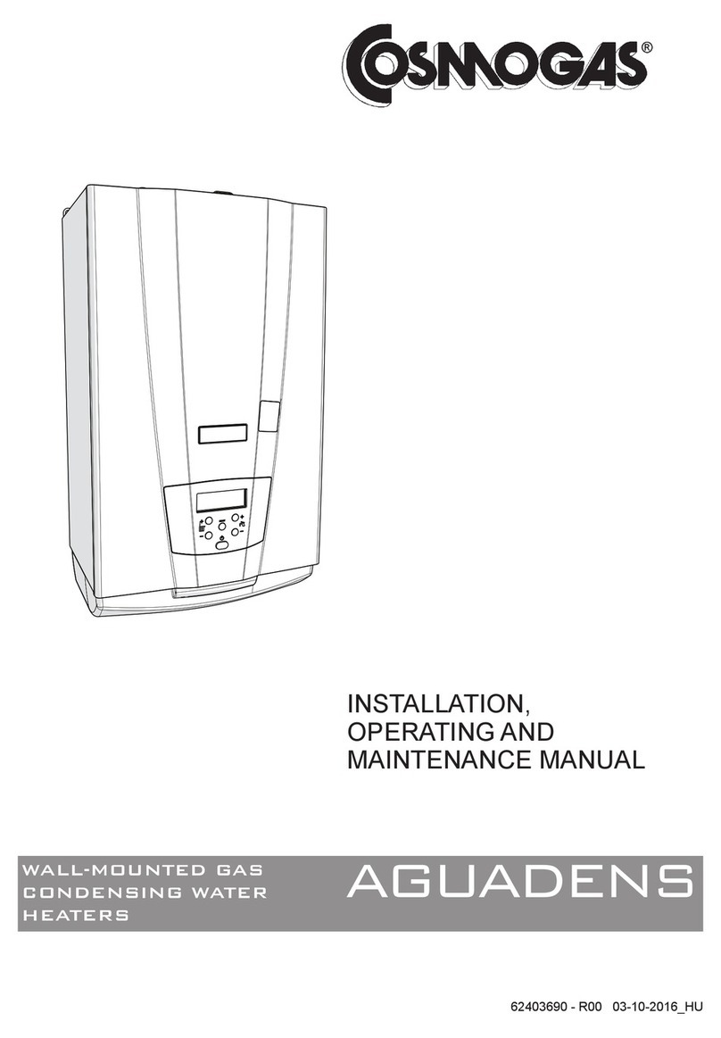
COSMOGAS AGUADENS Installation guide

62403581 - R00 07-01-2014_GB/IE
INSTALLATION,
OPERATING AND
MAINTENANCE MANUAL
AGUADENS
WALL-MOUNTED GAS
CONDENSING WATER
HEATERS

2
AGUADENS COSMOGAS
INDEX
1 - GENERAL SAFETY RECOMMENDATIONS ..................................................................................................4
1.1 - National laws and regulations .................................................................................................................................. 5
2 - GENERAL INFORMATION .............................................................................................................................6
2.1 - Presentation ............................................................................................................................................................. 6
2.2 - Model overview ........................................................................................................................................................ 6
2.3 - Manufacturer ............................................................................................................................................................ 7
2.4 - Symbols key............................................................................................................................................................. 7
2.5 - Maintenance............................................................................................................................................................. 7
2.6 - Warranty................................................................................................................................................................... 7
3 - MAIN COMPONENTS.....................................................................................................................................8
4 - OPERATION .................................................................................................................................................10
4.1 - Operation and intended use of the appliance .........................................................................................................11
4.2 - D.H.W. circulation pump performance curves.........................................................................................................11
4.3 - Examples of installation ......................................................................................................................................... 12
5 - INSTALLATION .............................................................................................................................................14
5.1 - Opening the packaging .......................................................................................................................................... 14
5.2 - Dimensions and minimum safety clearances......................................................................................................... 14
5.3 - Choosing suitable installation location ................................................................................................................... 14
5.4 - Mounting the appliance .......................................................................................................................................... 14
5.5 - Domestic hot and cold water.................................................................................................................................. 14
5.6 - Gas......................................................................................................................................................................... 15
5.7 - Condensate drain................................................................................................................................................... 16
5.8 - Safety valve............................................................................................................................................................ 16
5.9 - Hydraulic and gas connections .............................................................................................................................. 17
5.10 - Water softener (on request) ................................................................................................................................. 17
5.11 - Electrical connections........................................................................................................................................... 18
5.11.1 - Power supply cable connection............................................................................................................... 19
5.12 - D.H.W. buffer tank hydraulic layout...................................................................................................................... 19
5.12.1 - Anti- legionella precaution....................................................................................................................... 19
5.12.2 - External secondary return conguration ................................................................................................. 19
5.13 - Flue systems ........................................................................................................................................................ 20
5.13.1 - Exhaust ue with indipendent combustion air grille type B23 ................................................................. 21
5.13.2 - “Split 80/80PP” System (polypropylene) (Type C43; C53; C83) AGUADENS 16-22-27......................... 22
5.13.3 - “Split 80/80PP” System (polypropylene) (Type C43; C53; C83) AGUADENS 37 ................................... 23
5.13.4 - “Split 80/80PP” System (Type C43; C53; C83): accessories available................................................... 24
5.13.5 - “Split 80/80PP” System (Type C43; C53; C83): installation examples ................................................... 25
5.13.6 - “60/100PP vertical coaxial” System (polypropylene) (C13; C33 Type) ................................................... 26
5.13.7 - “60/100PP horizontal coaxial” System (polypropylene) (C13; C33 Type)............................................... 27
5.13.8 - “60/100PP Coaxial” System: accessories available................................................................................ 28
5.13.9 - “60/100PP Coaxial” System: installation examples ................................................................................ 29
5.13.10 - “80/125PP vertical coaxial” System (polypropylene) (C13; C33).......................................................... 30
5.13.11 - “80/125PP Coaxial” System: accessories available.............................................................................. 31
5.13.12 - “80/125PP Coaxial” System: installation examples .............................................................................. 32
6 - OPERATING .................................................................................................................................................33
6.1 - Operating ............................................................................................................................................................... 33
6.1.1 - User instructions ....................................................................................................................................... 33
6.1.2 - Filling the condensate drain siphon .......................................................................................................... 33
6.2 - General recommendations regarding the supply of gas ........................................................................................ 33
6.3 - Type of gas for which the appliance is regulated. .................................................................................................. 33
6.4 - Conversion of the appliance from one type of gas to another................................................................................ 34
6.5 - Ignition.................................................................................................................................................................... 36
6.6 - Measurement and adjustment of gas pressure adjustment ................................................................................... 37
6.7 - Measurement of combustion air pressure.............................................................................................................. 38
6.8 - Measurement and adjustment of CO2 levels ......................................................................................................... 39
6.9 - Adjusting the domestic hot water ow rate............................................................................................................. 40
7 - USE...............................................................................................................................................................41
7.1 - Valve positions ....................................................................................................................................................... 41
7.2 - Display ................................................................................................................................................................... 41
7.3 - Ignition procedure .................................................................................................................................................. 41
7.4 - “User menu” ........................................................................................................................................................... 42
7.5 - Adjustment of domestic hot water temperature...................................................................................................... 42
7.6 - Pump control features ............................................................................................................................................ 42

3AGUADENS
COSMOGAS
INDEX
7.7 - Pumps anti-block.................................................................................................................................................... 42
7.8 - Display Energy Saving mode ................................................................................................................................. 42
7.9 - “User menu” Parameters........................................................................................................................................ 43
7.10 - “Installer menu” & parameters.............................................................................................................................. 44
7.11 - Diagnostics........................................................................................................................................................... 46
7.11.1 - Diagnostics “Loc” block fault codes and potential solution...................................................................... 47
7.11.2 - Diagnostics “E” error fault codes and potential solutions ........................................................................ 49
7.11.3 - Diagnostics “AttE” alarm fault codes and potential solutions .................................................................. 50
8 - MAINTENANCE ............................................................................................................................................51
8.1 - General recommendations..................................................................................................................................... 51
8.2 - Casing removal ...................................................................................................................................................... 52
8.3 - Burner and fan removal.......................................................................................................................................... 53
8.4 - Gas burner and heat exchanger outer surface cleaning procedure....................................................................... 53
8.5 - Condensate siphon cleaning procedure................................................................................................................. 54
8.6 - Ignition and ame isonising electrode position....................................................................................................... 55
8.7 - Circulation pump replacement procedure .............................................................................................................. 55
8.8 - Domestic water ow meter replacement procedure............................................................................................... 56
8.9 - Safety valve replacement procedure...................................................................................................................... 56
8.10 - Procedure for draining the water heater............................................................................................................... 57
8.11 - Fan test mode procedure ..................................................................................................................................... 57
8.12 - Gas burner minimum and maximum performance test mode procedure............................................................. 57
8.13 - Checking the ionisation current............................................................................................................................ 57
8.14 - Water temperature measurement sensor testing procedures .............................................................................. 57
8.15 - AGUADENS models 16, 22 and 27 electrical connections .................................................................................. 58
8.16 - AGUADENS models 16, 22 and 27 internal multi-core wiring diagram................................................................ 60
8.17 - AGUADENS model 37 electrical connections ...................................................................................................... 62
8.18 - AGUADENS model 37 multi-core wiring diagram ................................................................................................ 64
9 - TECHNICAL DATA ........................................................................................................................................66
10 - COMMAND MENU DIAGRAM....................................................................................................................68
11 - ENGINEERS TEST MODE..........................................................................................................................69
12 - CE DECLARATION OF CONFORMITY......................................................................................................70
13 - WARRANTY................................................................................................................................................71
13.1 - General warranty conditions ................................................................................................................................ 71
13.2 - Instructions for lling-in the warranty card............................................................................................................ 71
13.3 - Warranty limitations.............................................................................................................................................. 71

4
AGUADENS COSMOGAS
If you smell gas
1. - Close the gas cock.
2. - Ventilate the room.
3. - Do not switch on any electric device, telephone included.
4. - From another room, call a professionally qualified
technician immediately or the gas supply company. Call
the Fire Service if the former are not available.
If you can smell combustion products
1. - Switch the appliance off.
2. - Ventilate the room.
3. - Call a professionally qualied technician.
Explosive or highly ammable products
Do not store or use explosive or highly ammable materials
such as paper, solvents, paints, etc...in the same room where
the appliance is installed.
Installation, modications
The gas appliance must be installed, calibrated or modied
by professionally qualied staff, in compliance with National
and local Standards, as wells as the instructions in this
manual.
Incorrect installation or poor maintenance can cause
injury/damage to persons, animals or objects, for which
the manufacturer cannot be deemed liable.
The appliance must be connected to an approved ue
system. Failure to comply with this regulation can lead to
serious risks for people and animals
A domestic hot water temperature level exceeding 51°C
can cause permanent injury/damage to people, animals and
objects. Special care should be taken to protect children, the
elderly and those with special needs using non-accessible
blending valves to limit the ow hot water temperature at
outlets.
The water heater ue system must not be modied by
unqualied person.
The ue system terminals should not be obstructed in any
way.
Do not leave parts of the packaging and any replaced parts
within the reach of children.
Seal the adjustment devices after every calibration.
In agreement with the provisions for use, the user must
keep the installation in good working order and guarantee
reliable and safe operation of the appliance.
We also highlight the importance of an annual scheduled
maintenance contract with a professionally qualified
technician.
The end user must have maintenance performed on the
appliance only by professionally qualied technicians in
accordance with this manual and in full compliance with
both local and national standards.
Before performing any cleaning or maintenance, disconnect
the appliance from the mains power supply.
After having performed any cleaning or maintenance works,
make sure that all internal etc.
This appliance is not intended for use by persons (including
children) with reduced physical and sensory conditions or
lack of experience and knowledge, unless they have been
given supervision or instruction concerning use of the
appliance by a person responsible for their safety.
This manual is an integral and essential part of the product
and must be kept carefully by the user, for possible future
consultation. If the appliance must be transferred or if you
should move and leave the unit to another user, always
ensure that this manual remains with the new user and/
or installer.
Any accessories or kits which might be added must be
original Cosmogas products.
This appliance must be intended only for the use for which
it has been expressly declared: production of domestic hot
water for civilian use.
Any contractual and extra contractual liability of the
manufacturer is excluded for damage caused by installation
errors or errors in use and however due to failure to comply
with the instructions given by the manufacturer or by failure
to comply with applicable national and/or local laws.
For safety reasons and respect for the environment, the
packaging elements must be disposed of in the relevant
separate waste collection centres.
In case of breakdown
In the case of appliance breakdown and/or malfunctioning,
deactivate it and do not attempt any repairs. Contact a
professionally qualied technician only. If components must
be replaced for repair to be successful, only use original spare
parts. Failure to comply with the above can jeopardise the
safety of the appliance.
Professionally qualied technician.
Professionally qualied technicians with certied training
covering gas boilers and/or gas water heaters as envisioned
by the law.
Technical drawings
All drawings in this manual relating to electrical wiring,
hydraulic and gas layouts are purely indicative. The external
services such as electrical cable types and sizes, water
services pipes and gas services must always be checked
by a professionally qualied technician or engineer to verify
compliance with all relevant standards, Laws and codes of
good practice.
Carbon Monoxide.
Every year deaths and serious injuries occur due to carbon
monoxide poisoning. This tragedies are avoidable if certain
preventative measures such as the following are undertaken:
Ensure that all boilers, water heaters, room heaters, stoves
and hobs which burn oil, natural gas, LP gas, coal, peat,
wood and wood pallets are serviced regularly. Servicing
is needed at least once per year to ensure safety. the
service person should be qualied and trained to service
the specic types of appliance
If an appliance is fitted in a dwelling, then a carbon
monoxide detector should always be tted. There are two
types avaiable: a simple detector works like a re alarm to
emit a loud noise and ashing light if carbon monoxide is
detected or a more sophisticated version which will also
switch off the appliance to provide more safety.
1 - GENERAL SAFETY RECOMMENDATIONS

5AGUADENS
COSMOGAS
1 - GENERAL SAFETY RECOMMENDATIONS
1.1 - National laws and regulations
- M.D. n°37 dated 22/01/2008 (former Law n°46 dated 05/03/90)
- Law n°10 dated 09/01/91
- Presidential Decree n°412 dated 26/08/93
- Presidential Decree n°551 dated 21/12/99
- Legislative Decree n° 192 dated 19/08/05
- Legislative Decree n° 311 dated 29.12.06
- UNI 7129 Standard
- UNI 7131 Standard
- UNI 11071 Standard
- IEC 64-8 Standard
All the gas appliances must be installed by a competent
and qualied person, in accordance with relevant clauses of
applicable standards and raccomandations. These include
but may not be limited to the following:
- I.S. 813 Domestic gas installations.
- I.S. 820 Non-Domestic gas installations.
- IEE Wiring Regulations.
- BS 5546:2010 - Specication for installation and maintenance
of gas-fired water-heating appliances of rated input not
exceeding 70 kW net.
- BS 5440-2:2009 - Flueing and ventilation for gas appliances
of rated input not exceeding 70 kW net (1st, 2nd and 3rd family
gases) specication for the installation and maintenance of
ventilation provision for gas appliances.
- BS 6644:2011 - Specification for the installation and
maintenance of gas-red hot water boilers of rated inputs
between 70 kW (net) and 1.8 MW (net) (2nd and 3rd family
gases).
- BS 6891:2005+A2:2008 - Installation of low pressure gas
pipework of up to 35 mm (R1 1/4) in domestic premises (2nd
family gas) specication.
- BS 5482-1:2005 - Code of practice for domestic butane and
propane gas burning installations. Installations at permanent
dwellings, residential park homes and commercial premises,
with installation pipework sizes not exceeding DN 25 for steel
and DN 28 for corrugate stianless steel or copper.
- BS 5482-2:AMD 12046: June 2001 - Domestic butane and
propane gas burning installations. Installations in caravans
and non-permanent dwellings.
- BS 5482-3:2005 - Domestic butane and propane gas burning
installations. Installations in boats yachts and other vessels.
- Building regulations issued by Department of the Environment
and Building Standards Regulations.
- Gas safety (Installation and Use) Regulations current issue.
- BS 6700 - Design, installation, testing and maintenance of
services supplying water for domestic use within buildings
and their cartilages - Specication.
- UK Health and safety at work Act.
- All relevant Building Regulations.
- Local Water Bye Laws.
- Water Regulations.
- Health & Safety legislation.
Failure to install this appliance correctly could lead to
prosecution. It is your own interest and that of safety to ensure
that the law is complied with. Manufacturer’s instructions must
not be interpreted as over-riding statutory obligations under
any circumstances.

6
AGUADENS COSMOGAS
2.1 - Presentation
Congratulations! You have purchased one of the best
products on the market. Each individual part is proudly
designed, produced, tested and assembled within the
COSMOGAS establishment, thus guaranteeing the
best quality control. This product has been developed
thanks to the COSMOGAS who pay the highest
respect to the environment with class 5 classication
as being the last polluting as envisioned by EN297
(and EN 483) Technical Standards. COSMOGAS
place great importance to the end-of-life cycle for
their appliances with all of components being easily
separated for recycling.
2.2 - Model overview
AGUADENS XX
16 = Water heater with maximum heat input of 25.5 kW
22 = Water heater with maximum heat input of 34.8 kW
27 = Water heater with maximum heat input of 43.0 kW
37 = Water heater with maximum heat input of 60.0 kW
Condensing, indoor, pre-mixed, ecological gas water heater.
2 - GENERAL INFORMATION

7AGUADENS
COSMOGAS
2.3 - Manufacturer
COSMOGAS srl
Via L. da Vinci 16
47014 - Meldola (FC) Italia
Tel. 0543 498383
Fax. 0543 498393
www.cosmogas.com
2.4 - Symbols key
ATTENTION !!!
Electric shock hazard. Failure to comply with these
recommendations can jeopardise the good working order of
the appliance or cause serious damage to persons, animals
or objects.
ATTENTION !!!
General hazard. Failure to comply with these recommendations
can jeopardise the good working order of the appliance or
cause serious damage to persons, animals or objects.
Important indication symbol.
2.5 - Maintenance
It is recommended to perform regular yearly maintenance of
the appliance for the following reasons:
- to maintain a high yield and manage the domestic hot water
plant economically (with low fuel consumption);
- to achieve a high level of safety;
- to maintain the level of environmental compatibility of the
combustion high;
Offer your customer a scheduled maintenance contract.
2.6 - Warranty
see chapter 13.
2 - GENERAL INFORMATION

8
AGUADENS COSMOGAS
1 - Command and control board
2 - Electric connections board
3 - Electric control board box
4 - Lower cover
5 - Recirculation tting cap
6 - Water ow rate measuring device
7 - Cold water inlet temperature sensor (1007)
8 - Fan
9 - Non-return valve
10 - Air/gas manifold
11 - Double D.H.W. output sensor (1001 and 1005)
12 - Cold water inlet tting
13 - D.H.W. outlet tting
14 - Recirculation Pump
15 - Detection electrode
16 - Wall xing brackets
17 - Secondary return manual control valve
18 - Conveying tting
19 - Combustion air and exhaust ue connection
20 - Combustion analysis points
21 - Double exhaust ue temperature sensor (1006 and
1014)
22 - Spark generator
23 - Ignition cables
24 - Combustion gases non-return valve.
25 - Air inlet manifold
26 - Gas valve
27 - Front casing
28 - Safety valve
29 - Display
30 - Control board
31 - Gas valve adjustment service access hatch
3 - MAIN COMPONENTS
Figure 3.1 - Water heater internal components
16
28
6
8
25
16
26
4
3
2
21
24
22
9
19
11
23
17
10
15
20
12
7
31
1
13
18
30
5
29
14
27
020003.01.042

9AGUADENS
COSMOGAS
32 - Pump air vent
33 - Front casing xing tabs
34 - Left ignition electrode
35 - Right ignition electrode
36 - Gas burner viewing port
37 - Flue condensate collection collar drain pipe (connected
to siphon)
38 - Burner
39 - Air/gas mixing unit
40 - Condensate drain siphon
41 - Safety valve drain pipe
42 - Non-return valve
43 - Condensate collection tank
44 - Domestic hot water temperature sensor (1002)
3 - MAIN COMPONENTS
Figure 3.1 - Water heater internal components
44
38
32
35
33
41
34
43
37
39
40
42
36
020003.01.043

10
AGUADENS COSMOGAS
Key to gure 4.1:
1 = Water heater
2 = Combustion air intake spigot
3 = Exhaust ue spigot
4 = Exhaust ue temperature sensor 1 (Par. 1006)
5 = Exhaust ue temperature safety sensor 2 (Par. 1014)
6 = Sealed chamber
7 = Water collection tub
8 = D.H.W. outlet temperature sensor 1 (Par. 1001)
9 = D.H.W. outlet temperature safety sensor 2 (Par. 1005)
10 = Burner
11 = Titanium plated stainless steel VRC type heat exchanger
12 = Fan
13 = Cold water inlet temperature sensor (Par. 1007)
14 = Condensate collection siphon with sediment decanter
15 = Air/gas mixer
16 = Pneumatic gas valve
17 = Safety valve
18 = Secondary return manual control valve
19 = Recirculation pump
20 = Non-return valve
21 = Water ow rate measuring device
22 = Secondary return connection
23 = Secondary return blanked connection
24 = Domestic hot water sensor (Par. 1002)
25 = Gas isolation valve
26 = Gas inlet
27 = Domestic cold water inlet
28 = Safety valve condensate drain collector
29 = Domestic hot water outlet
4 - OPERATION
Figure 4.1 - Hydraulic layout
AGUADENS
Figure 4.2 - Secondary return manual control valve
020003.01.044
OPEN
Secondary
return not present
CLOSE
Secondary
return present 020003.01.045

11 AGUADENS
COSMOGAS
4.1 - Operation and intended
use of the appliance
This product is a condensing gas appliance, intended for
the production of domestic hot water for use by people.
Consider the D.H.W. circulation pump performance curves
as detailed in paragraph 4.2 and as illustrated in gure 4.3.
The temperature of the domestic hot water can be adjusted
by following the relevant procedure in chapter 7.5.
This appliance must be connected to a domestic hot
water distribution system which has adequately sized
pipes to convey the correct water volume and all pipes
should be tted with good quality insulation to optimise
the performance of the water heater.
Before installation of the domestic cold and hot water
services should be ushed thoroughly in order to remove
any residues or impurities which could compromise the
good working order of the appliance.
4 - OPERATION
Figure 4.3 - Curve of the domestic water circuit losses
Head losses (bar)
Water ow rate (l/min)
This appliance is not suitable for installation outdoors.
It must not be exposed to temperature below zero or
temperature above 50°C. Select a suitable sheltered
location for the appliance.
This appliance must be installed in a location which will
not cause damage to objects or property in the event of
water leaking from within the appliance or connections at
the appliance.
Check gure 5.1 concerning the minimum safety
distances for installation and future maintenance.
4.2 - D.H.W. circulation pump
performance curves
The pump curves as shown in gure 4.3 outline the
performances which can be archived. It is the designer’s
responsability to ensure that the available pump head
pressure will achieve the desired results.
Key to gure 4.3
I = Aguadens 16
II = Aguadens 22 and Aguadens 27
III = Aguadens 37

12
AGUADENS COSMOGAS
Figure 4.4 - Example of installation basic
Figure 4.6 - Example of installation with storage
tank
4.3 - Examples of installation
In gures 4.4, 4.5, 4.6, 4.7, 4.8 and 4.9 you can see some
examples of installation.
Figure 4.5 - Example of installation with
recircolation and external pump
Figure 4.7 - Example of installation with storage
tank with supply direct to the water heater
4 - OPERATION

13 AGUADENS
COSMOGAS
4 - OPERATION
Figure 4.8 - Example of installation with solar panel and storage tank
Figure 4.9 - Example of installation with solar panel

14
AGUADENS COSMOGAS
5.1 - Opening the packaging
The appliance is supplied in cardboard packaging. Open
following the instructions given on the aps of the packaging
itself.
5.2 - Dimensions and minimum
safety clearances
It is necessary to leave free spaces around the appliance as
illustrated in gure 5.1 both for installation and maintenance.
5.3 - Choosing suitable
installation location
ATTENTION !!! The appliance must be installed
exclusively on a solid, vertical wall, which can support
the weight.
The appliance must be installed in a suitable room taking
into account the following factors:
- connection of the exhaust/air intake pipes;
- connection of the gas supply pipe;
- connection to the cold water supply;
- connection of the domestic hot water supply;
- electrical connection;
- connection of the siphon and safety valve to a suitable
drain;
5.4 - Mounting the appliance
Refer to gure 5.3:
1.- place the paper template, provided with the appliance,
against the wall;
2.- check that the template is square;
3.- mark the holes for the plugs and hydraulic ttings on the
wall;
4.- remove the paper template;
5.- make the holes “A” and introduce the wall plugs “B”;
6.- hang the appliance on the plugs “C”
7.- make the appliance hydraulic and gas connections;
8.- make the hydraulic ttings.
5.5 - Domestic hot and cold water
ATTENTION !!! If water hardness exceeds 25°F
(250 mg/l) a polyphosphates water softener must
be installed on the incoming cold water supply (see
paragraph 5.10).
ATTENTION !!! Install a lter with mesh no wider
than 0.5 mm² in the domestic cold water inlet.
ATTENTION !!! The domestic hot water
piping materials and ttings must be capable of
withstanding temperatures of a least 95°C and 10
bar pressure. These circuits must be protected with
suitable expansion together with both temperature and
pressure relief safety devices in accordance with all
relevant safety standards.
In gure 5.2 the service and maintenance valves are not
shown. Hydraulic and gas connections should be tted with
isolation valves to accomadate service and maintenance
works.
1 - 3/4” recirculation
2 - 3/4” D.H.W. outlet
3 - 3/4” gas inlet
4 - 3/4” cold water inlet
5 - Fumes exhaust/Air intake
6 - Support attachments
7 - Ø20 condensate drain
A = 305 mm (MODELS 16-22-27) - 484 mm (MODEL 37)
B = 120 mm (MODELS 16-22-27) - 175 mm (MODEL 37)
C = 125 mm (MODELS 16-22-27) - 304 mm (MODEL 37)
5 - INSTALLATION
Figure 5.1 - Minimum safety distances
Figure 5.2 - Dimensions and attachments centre to
centre distances

15 AGUADENS
COSMOGAS
5 - INSTALLATION
5.6 - Gas
ATTENTION !!! It is prohibited to operate the
appliance with the incorrect gas type. Ceck the data
label on the appliance for Natural gas (G20) or Propane
gas (G31) to ensure that the correct appliance in being
installed.
ATTENTION !!! Check that the gas and supply
pressure are those for which the appliance has been
adjusted.
Two situations are possible:
A - the gas and supply pressure correspond to the
adjustment of the appliance. In this case, it can be
connected;
B - the gas and supply pressure do not correspond to the
adjustment of the appliance. In this case, the appliance
must be converted to the type of gas and supply
pressure corresponding to those of the supply available.
The appliance is provided with the relevant gas conversion
kit.
Before the gas pipes are purged it is essential to ensure
that the internal surfaces are clean and free of metal or
plastic lings or any other solid pieces or liquids;
An isolation valve must be installed on the gas supply
pipe adjacent to the appliance;
ATTENTION !!! Before supplying gas to the
appliance, it is essential that the gas pipes have been
pressure tested in accordance with the most recent
applicable gas standards.
to prevent damage to the appliance gas valve, the
supply pressure should not exceed 50 mbar under any
circumstances;
if the gas pipe-work must be tested in excess of 50
mbar, ensure that the appliance is fully isolated.
Figure 5.2 shows the position and the diameter of the gas
connection on the appliance. Ensure that the gas service pipe-
work is adequately sized to provide the maximum volume ow
rate at the required minimum pressure.
Figure 5.3 - Appliance wall xing detail

16
AGUADENS COSMOGAS
Figure 5.4 - Safety valve drain and condensate
drain connection
BC
A
020002.01.005
D
A
E
020002.01.006
5 - INSTALLATION
5.7 - Condensate drain
There is a siphon inside the appliance for the evacuation
of condensate (see gure 3.1 detail “40”) and to prevent
combustion products from escaping, whose end
corresponds to the pipe “B” in gure 5.4. This termination
must be conveyed into an anti-odour siphon (gure
5.8 detail “G”) to prevent bad odours returning into the
environment (the anti-odour siphon “G” is supplied on
request). The tank “A” is mounted in the factory as indicated
in gure 5.4, the exhaust pipe “F” is mounted in the factory
as indicated in gure 5.5. In particular, the condensate
discharge must comply with the following:
for room used for residential purposes and for ofce with
more than 10 users, it can be connected to the domestic
waste disposal plant by means of appropriate siphon
with disjunction capable of preventing the pressurisation
of the system (siphon prepared within appliance) and to
prevent the return of bad odours from the sewer (detail
“G” in gure 5.8). If the room used for ofce purposes
has less than 10 users, before connection with the
domestic waste drain, a condensate neutraliser is good
practice (see chapter 9 for the value of acidity of the
condensate and the quantities).
be connected to a plastic (not copper) drain pipe with a
minimum internal pipe diameter equal to or greater than
13 mm;
be installed in a way to prevent the liquid from freezing;
therefore pay attention to any external passings. It is
prohibited to drain into gutters or drainpipes;
to slope continuously towards the drain point, avoid high
points, which could pressurise the pipe;
5.8 - Safety valve
The appliance is protected against overpressures by a
safety valve calibrated to 10 bar (see gure 3.1
detail “28”). The safety valve drain (detail “C” in gure
5.4), along with the condensate drain (detail “B” in gure
5.4) must be conveyed to a pipe “F” (see gure 5.5) with
minimum internal diameter of 13 mm. The pipe “F” must be
then taken to the anti-odour siphon (detail “G” gure 5.8).
This drain with siphon is used to prevent overpressures if
the valve is opened and makes it possible for the user to
check the eventual intervention. The pipe “F” in gure 5.5
is supplied by standard along with the tank “A” in gure
5.4. The anti-odour siphon “G” in gure 5.8 is provided on
request.
ATTENTION !!! If not connected to the drain,
whenever the safety valve should intervene, it could
cause damage to persons, animals or objects.
Figure 5.5 - Condensate drain pipe
A
F
020002.01.017

17 AGUADENS
COSMOGAS
Figure 5.6 - Water and gas connections
5 - INSTALLATION
E
A
F
BCD
G
020003.01.004
Figure 5.8 - Siphon funnel (on request)
F
G
020002.01.028
min10 mm
max 30 mm
5.9 - Hydraulic and gas connections
The appliance is supplied as per standard with the ttings
illustrated in gure 5.6, where:
A = Ø 18 recirculation
B = domestic hot water Ø 18
C = 3/4” gas isolation valve (EN 331 type-approved)
D = 1/2“ domestic cold water isolation valve
E = gas Ø 18
F = domestic cold water Ø 18
Once the hydraulic and gas connections have been made,
proceed with assembly of the lower cover “G” as indicated
in gure 5.6.
5.10 - Water softener (on request)
If the appliance is installed in a geographical area where
domestic water has hardness exceeding 25°F (250 mg/l), a
polyphosphates softener must be installed on the cold water
supply (see gure 5.7 detail “B”), in order to safeguard the
appliance from any lime scale deposits.
Proceed as follows for installation (refer to gure 5.7):
1.- connect the softener “B” to the isolation valve “A”;
2.- mount the isolation valve “A” to the appliance tting;
3.- proceed with the installation of the cold water inlet pipe
into the tting behind the softener “B”;
4.- before re-mounting the lower cover, it is necessary
to cut out the plastic section between “C” and “D” to
accomodate the softener “B”.
ATTENTION !!! Please note that if the water
hardness levels are likely to be extremely high, it would
be essential to consult with a water softening specialist
who may recommend a more sophisticated system. In
this regard, we would recommend that the incoming
water supply should be tested in advance of any
decision to purchase the appliance.
Figure 5.7 - Polyphosphates softener
(on request)
B
A
C
B
A
D
020003.01.008

18
AGUADENS COSMOGAS
5.11 - Electrical connections
ATTENTION !!! The appliance is only electrically
safe when it has been correctly connected to an
efcient earth circuit, performed as envisioned by the
current Safety Standards.
This fundamental safety requirement must be met. If in
doubt, request a thorough control of the electric plant by a
professionally qualied technician.
Have a professionally qualied technician check that the
electric plant is suitable for the electric power required by
the appliance, indicated on the plate.
The appliance must be connected to the mains electricity
using a cable coupler. The use of adapters, multiple
sockets, extensions, etc. is not allowed.
The appliance must be connected to the mains electricity
using a three-polar electric cable, with double isolation,
minimum section of 1.5 mm² and resistant to a minimum
temperature of 70°C (characteristic T).
For connection to mains electricity, a bi-polar switch
must be envisioned in the vicinity of the appliance with a
contacts opening distance of at least 3mm, as envisioned
by the current regulations on the subject.
Respect the polarity between the neutral phase during
connection of the appliance.
Make sure that the water plant pipes are not used as
earth points for the electric or telephone plant. This
piping is not suitable for this purpose, moreover, serious
corrosion damage would occur in a very short time, on
the appliance, piping and radiators.
ATTENTION !!! the appliance is not protected
against the effects caused by lightening.
D
C
C
C
B
A
020003.01.009
5 - INSTALLATION
Figure 5.9 - Electric connections
Key for gure 5.9
A = Commands board box;
B = Electric connections board lid;
C = Connections lid closing aps;
D = Electric connections board;
Key for electric contacts
PM = Not used
CH = Not used
BUS = Not used
TA = Not used
0-10 = Not used
SE = Not used
SB = Storage tank sensor (if present)
MF = Multi-function output
PE = Boiler pump (if present)
DN = Not used
(2 = Neutral; 3 = Line)
L1 = Appliance power supply line
N = Appliance power supply neutral
EARTH SYMBOL = Earth contacts
020002.01.010

19 AGUADENS
COSMOGAS
5.11.1 - Power supply cable connection
Proceed as follows to connect the power supply cable (refer
to gure 5.9):
1.- use a three-polar cable with double isolation, with
minimum section of 1.5 mm²
2.- remove the casing from the appliance following the
relevant instructions in paragraph 8.2;
3.- rotate the panel “A” towards the front of the appliance;
4.- operate on the aps “C” and open the lid “B” as
indicated by the arrow;
5.- lay the power supply cable through the fairlead in
proximity of the contacts “L1”, “N” and earth symbol;
6.- strip the cable, making sure to keep the earth cable
(yellow green) 20 mm longer than the other two;
7.- connect the yellow-green cable to the earth terminals
(see symbol)
8.- connect the brown cable (Phase) to the terminals L1
9.- connect the blue cable (Neutral) to the terminals N
5.12 - D.H.W. buffer tank
hydraulic layout
The hydraulic connection must be made as in gure 5.10.
Proceed as follows for the electric connection (refer to the
gure 5.9):
1.- disconnect the electric power supply from the appliance;
2.- disconnect and remove the temperature sensor (detail
“44” in gure 3.1) from the domestic hot water outlet pipe;
3.- lay a bi-polar electric cable with minimum section of 1.5
mm², which goes from the appliance to the storage tank
temperature sensor and connect it to the appliance at
terminalss “8” and “9” (SB);
5 - INSTALLATION
Figure 5.10 - water connection to the storage tank
KEY
1 AGUADENS water heater
2 Recirculation (if activated) *
3 Domestic hot water outlet
4 Gas inlet
5 Cold water
6 Storage tank
7 Storage tank load pump
8 Storage tank sensor
9 Domestic utilities
10 Hydraulic safety unit (by the installer)
11 Cold water inlet
12 Some state require this safety
pressure-temperature relief valve
* The recirculation line is not mandatory.
4.- connect the other end of the cable to the storage tank
temperature sensor;
5.- introduce the temperature sensor inside the storage tank
sample point (see gure 5.10 detail “8”).
6.- Connect the electric power of the storage tank pump (see
gure 5.10 detail “7”) to “PE” terminals of the water heater.
The AGUADENS appliances can be connected to a
storage tank even following installation. In this case,
the parameter 3012 must be set at the value of 1.
The temperature of the water stored inside the storage tank
can be selected by the user in a range between 40 and
70°C.
ATTENTION !!! A domestic hot water
temperature level exceeding 51°C can cause permanent
injury/damage to persons, animals and objects.
Children, the elderly and disabled must be protected
against the potential risks of scalding, by introducing
devices that limit the temperature of use of domestic
hot water to utilities.
5.12.1 - Anti- legionella precaution
If the appliance is connected to a storage tank for the
preparation of domestic hot water, a disinfection cycle is
envisioned against the legionella bacterium. This cycle
envisions taking the storage tank to a temperature of 60°C
(temperature at which the legionella bacteria dies) at least
every week. It is for this reason that the water (at certain
times) can reach the utilities at a higher temperature that
than set with the relative command.
ATTENTION !!! A domestic hot water
temperature level exceeding 51°C can cause permanent
injury/damage to persons, animals and objects.
Children, the elderly and disabled must be protected
against the potential risks of scalding, by introducing
devices that limit the temperature of use of domestic
hot water to utilities.
5.12.2 - External secondary return
conguration
If the appliance is envisioned with external recirculation
unit, the recirculation cut-off valve (detail of gure 4.2) must
be turned to the closed position.

20
AGUADENS COSMOGAS
5.13 - Flue systems
ATTENTION !!! The relevant national and local
regulations must be strictly adhered to when installing
the exhaust ue and combustion air pipes.
ATTENTION !!! The exhaust ue gases from
the appliance can reach 90°C in certain conditions.
Therefore, the plastic ue components must be capable
of withstanding high temperatures and they must be
approved for these specic appliance.
ATTENTION !!! This appliance is the
“condensing” type. The polypropylene materials used
in the manufacture of plastic exhaust ue system
which are approved for use are designed to prevent
corrosion which would otherwise be caused to the
acidity of the condensate. AISI316 stainless steel
exhaust ue system can also be designed for this
purpose.
Regarding this, remember that the appliances of this
type must have exhaust and intake pipes supplied by the
manufacturer of the appliance itself. Other types of pipes,
if used, must however be type-approved for this intended
use. The types of exhaust for which the appliance is
approved are given in the features table at the end of the
manual under “type” and o the features plate afxed to the
appliance, also under “type”. The symbols used to dene
exhaust is reported below:
- B23, separated with intake in room and exhaust through
wall or roof.
ATTENTION !!! If the appliance is installed with the
B23 type exhaust, it will take in air for combustion from
the surrounding environment. Therefore, all precautions
must be taken regarding ventilation of the rooms, which
are prescribed by the national and/or local Standards.
- C13, coaxial in vertical wall
- C33, coaxial at the roof
- C43, separated with exhaust in ue, combined with intake
in common channel.
ATTENTION !!! The appliances installed in type
C43 must only be connected to conventional ues.
- C53, separated with exhaust on roof and intake on wall or
however, in two potentially different pressure points.
- C63, the appliance can be tted to type-approved exhaust
and intake pipes of other brands.
ATTENTION !!! With the C63 type exhaust,
the condensate coming from the chimney cannot be
conveyed into the appliance.
- C83, separated with wall intake or another point
independent from the intakes of other appliances and
ue exhaust.
Figure 5.11 - Exhaust/intake systems
5 - INSTALLATION
Table of contents
Other COSMOGAS Water Heater manuals
Popular Water Heater manuals by other brands

Atwood
Atwood GE6-240V owner's manual

RBI
RBI FUTERA III Series HeatNet Installation & operation manual

auer
auer Edel Air 200 User instruction manual

Eurofred
Eurofred daitsu WITD-AQUATANK HP Series Installation and maintenance manual

Kenmore
Kenmore Power Miser 12 153.320392 HT owner's manual

Bosch
Bosch Compress 3000 DW FOO installation instructions

Rointe
Rointe D SERIES instruction manual

clage
clage DEX Next L Operating and installation instructions

A.O. Smith
A.O. Smith BT- 80 Installation & operating instructions

hajdu
hajdu AQ STA200C Usage instructions

Bosch
Bosch TR 6000R Series operating instructions

Raypak
Raypak RAYTHERM 133-4001 Installation & operating instructions