EN
Operating instructions
Solenoid interlock AZM 170
EN Operating instructions...................... pages 1 to 6
Translation of the original operating instructions
FR
Vous trouverez la version
actuelle du mode d’emploi dans
votre langue nationale ofcielle
sur l’Internet, www.schmersal.
net.
ES
Encontrará el manual de
instrucciones actual en su
idioma ocial de la UE en nu-
estra página de Internet www.
schmersal.net.
NL
U vindt de huidige versie van
de gebruikshandleiding in uw
ofciële landstaal op het Inter-
net, www.schmersal.net.
IT
Il manuale d‘istruzioni aggior-
nato nella vostra lingua (lingua
ufciale UE) è scaricabile in
Internet all‘indirizzo www.
schmersal.net.
JP
EU公用語で書かれた最新の
取扱説明書は、インターネッ
(www.schmersal.net)からダウ
ンロードできます。
1
1 About this document
1.1 Function
This operating instructions manual provides all the information you
need for the mounting, set-up and commissioning to ensure the safe
operation and disassembly of the safety switchgear. The operating inst-
ructions must be available in a legible condition and a complete version
in the vicinity of the device.
1.2 Target group: authorised qualied personnel
All operations described in this operating instructions manual must
be carried out by trained specialist personnel, authorised by the plant
operator only.
Please make sure that you have read and understood these operating
instructions and that you know all applicable legislations regarding
occupational safety and accident prevention prior to installation and
putting the component into operation.
The machine builder must carefully select the harmonised standards to
be complied with as well as other technical specications for the selec-
tion, mounting and integration of the components.
1.3 Explanation of the symbols used
Information, hint, note:
This symbol is used for identifying useful additional information.
Caution: Failure to comply with this warning notice could
lead to failures or malfunctions.
Warning: Failure to comply with this warning notice could
lead to physical injury and/or damage to the machine.
1.4 Appropriate use
The products described in these operating instructions are developed to
execute safety-related functions as part of an entire plant or machine. It
is the responsibility of the manufacturer of a machine or plant to ensure
the proper functionality of the entire machinery or plant.
The safety switchgear must be exclusively used in accordance with the
versions listed below or for the applications authorised by the manufac-
turer. Detailed information regarding the range of applications can be
found in the chapter "Product description".
1.5 General safety instructions
The user must observe the safety instructions in this operating instruc-
tions manual, the country-specic installation standards as well as all
prevailing safety regulations and accident prevention rules.
Further technical information can be found in the Schmersal
catalogues or in the online catalogue on the Internet: www.
schmersal.net.
The information contained in this operating instructions manual is provi-
ded without liability and is subject to technical modications.
If multiple safety components are wired in series, the Perfor-
mance Level to EN ISO 13849-1 will be reduced due to the re-
stricted error detection under certain circumstances. The entire
concept of the control system, in which the safety component
is integrated, must be validated to EN ISO 13849-2.
There are no residual risks, provided that the safety instructions as well
as the instructions regarding mounting, commissioning, operation and
maintenance are observed.
Content
1 About this document
1.1 Function..............................................1
1.2 Target group: authorised qualied personnel..................1
1.3 Explanation of the symbols used . . . . . . . . . . . . . . . . . . . . . . . . . . .1
1.4 Appropriateuse........................................1
1.5 General safety instructions . . . . . . . . . . . . . . . . . . . . . . . . . . . . . . .1
1.6 Warningaboutmisuse...................................2
1.7 Exclusionofliability.....................................2
2 Product description
2.1 Orderingcode .........................................2
2.2 Specialversions........................................2
2.3 Destinationanduse.....................................2
2.4 Technicaldata.........................................2
2.5 Safety classication .....................................3
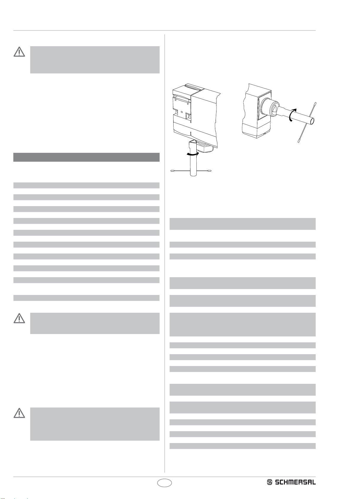
3 Mounting
3.1 General mounting instructions . . . . . . . . . . . . . . . . . . . . . . . . . . . . .3
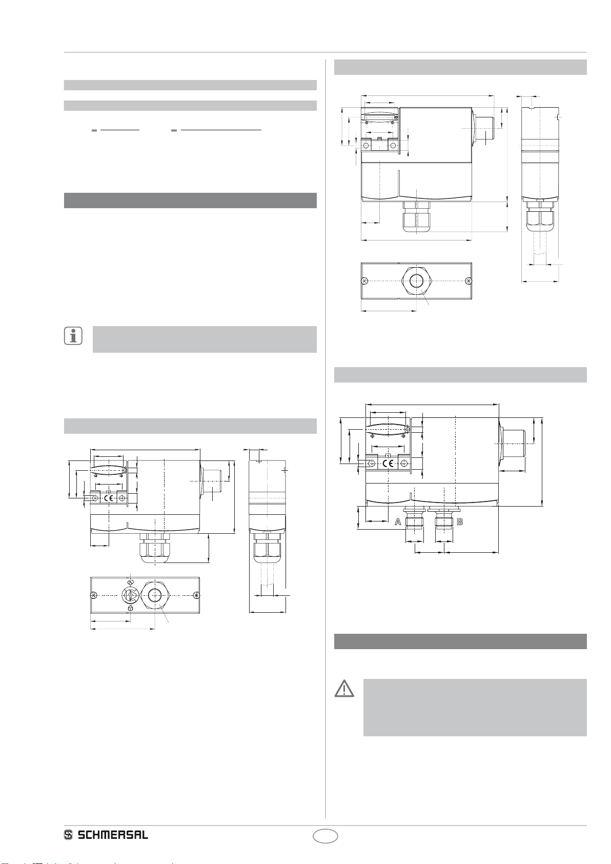
3.2 Dimensions ...........................................3
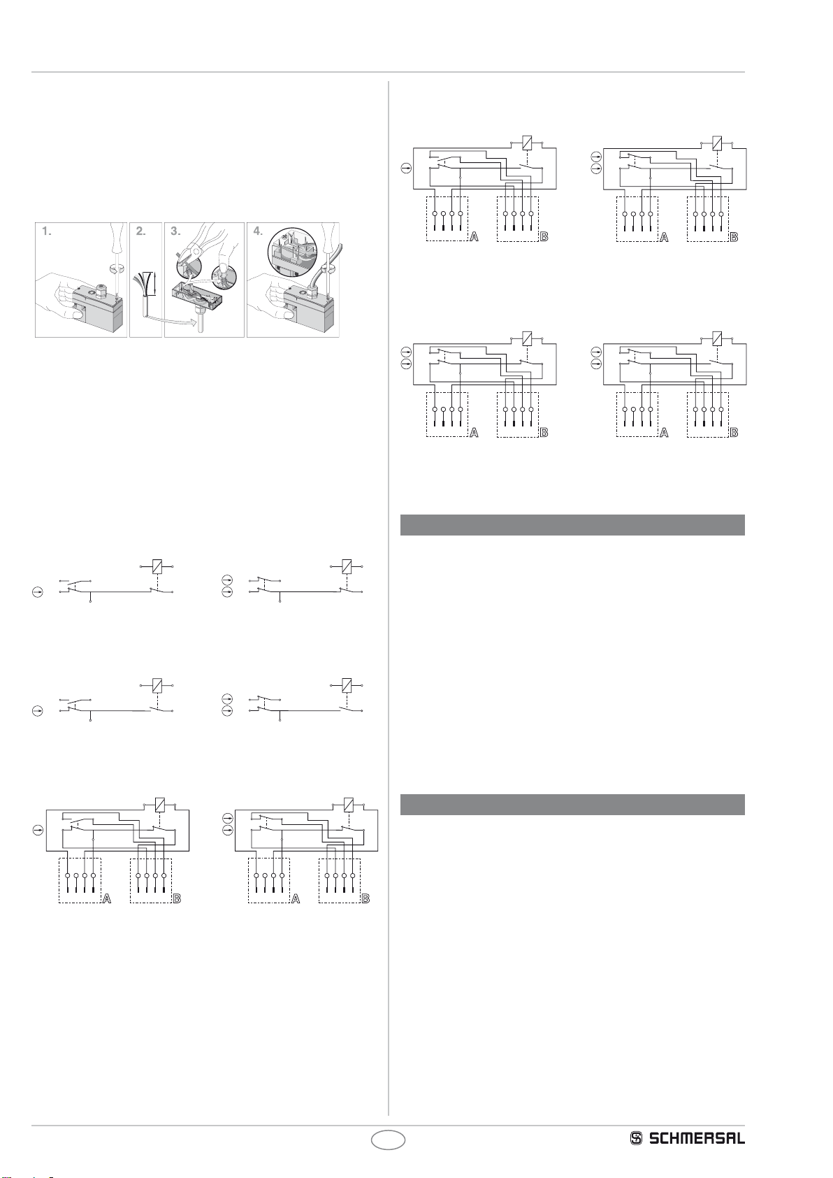
4 Electrical connection
4.1 General information for electrical connection. . . . . . . . . . . . . . . . . .3
4.2 Contactvariants........................................4
5 Set-up and maintenance
5.1 Functionaltesting.......................................4
5.2 Maintenance ..........................................4
6 Disassembly and disposal
6.1 Disassembly...........................................4
6.2 Disposal..............................................4
7 Appendix
7.1 ECDeclarationofconformity..............................5
x.500 / v.A. / 08.2009 / BZ-Nr. 50122-20V900 / Teile-Nr. 1122371-EN / Ausgabe Q


 user manual")


