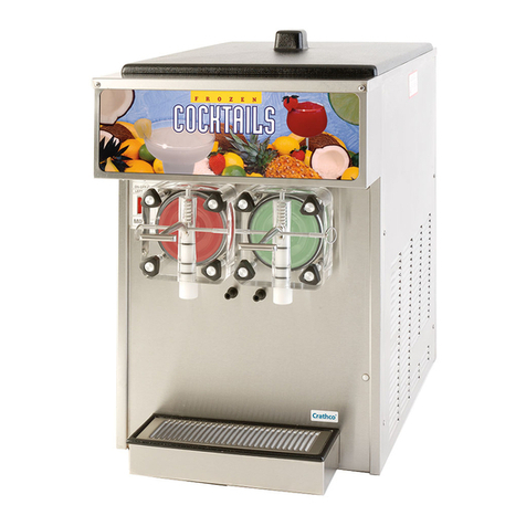
Schroeder America S-1 User manual

Please refer to the Schroeder America website (www.schroederamerica.com)
for information relating to Schroeder America installation and Service
Manuals, Instruction Sheets, Technical Bulletins, Service Bulletins, etc.
INSTALLATION INSTRUCTION, PARTS LIST
AND CONFIGURATION GUIDE
FOR THE
NON-CARBONATED
BEVERAGE DISPENSER (STARLINE)
Dispenser Model No. 900
NOTICE:
The information contained in this document is subject to change without notice.
SCHROEDER AMERICA MAKES NO WARRANTY OF ANY KIND WITH REGARD TO THIS MATERIAL, INCLUDING,
BUT NOT LIMITED TO, THE IMPLIED WARRANTIES OF MERCHANTABILITY AND FITNESS FOR A PARTICULAR
PURPOSE. SCHROEDER AMERICA shall not be liable for errors contained herein or for incidental consequential
damages in connection with the nishings, performance, or use of this material.
This document contains proprietary information which is protected by copyright. All right reserved.
© Copyright 2008 by Schroeder America, all rights reserved.
THIS DOCUMENT CONTAINS IMPORTANT INFORMATION
This manual must be read and understood before the installation and operation of this dispenser.
Schroeder America
5620 Business Park • San Antonio, TX 78218
210.662.8200 • Fax: 210.667.2600 • www.schroederamerica.com
Toll-Free 877.404.2488
Rev: 03/12
PN: 805-0001

1. OVERALL DIMENSIONS
Model: Width: Depth: Height:
S-1 8” 20 1/8” 29”
S-2 16 1/8” 20 1/8” 29”
2. SHIPPING WEIGHT
Model: Base: Bowl:
S-1 48lbs 10lbs (1)
S-2 77lbs 10lbs (2)
3. BOWL CAPACITY
Model: Capacity:
S-1, S-2 5 Gallons (18.9) Liters
4. AMBIENT OPERATING TEMPERATURE
40˚F TO 90˚F
5. ELECTRICAL REQUIREMENTS
Operating voltage 115V, 60HZ
6. UNPACKING AND INSPECTION
NOTE
This unit was thoroughly inspected before leaving the factory and the carrier has accepted and
signed for it. Any damage or irregularities should be noted at time of delivery (or not later than 5
days from date of delivery) and immediately reported to the delivering carrier. Request a written
inspection report from Claims Inspector to substantiate any necessary claim. File claim with the
delivering carrier, not with Schroeder America.
A. After unit has been unpacked, remove shipping tape and other material.
B. Unpack LOOSE-SHIPPED PARTS. Make sure all items are present and
in good condition.
7. IDENTIFICATION OF LOOSE-SHIPPED PARTS
A. SPRAY TUBE BRUSH is used for general cleaning.
B. SPRAY TUBE ASSEMBLY to be installed after BOWL GASKET and BOWL have
been installed.
C. DRIP TRAY to be installed on unit, then CUP REST to be installed in drip tray.
D. BOWL COVER to be installed on bowl after bowl has been lled with product.
E. ALLEN WRENCH used when adjusting drive magnet.
8. SELECTING LOCATION
NOTE
This unit may either be island-mounted or installed on a front or rear counter.
Locate unit so the following requirements are satised.
A. Unit must be installed on solid and level countertop.
2

B. A minimum of 12 inches air space must be maintained between unit sides and
back panels and nearest wall or obstruction to allow for circulating air to cool
refrigeration system.
C. Adequate clearance must be maintained above unit to replenish product supply
and also remove bowl cover, bowl, and spray tube for periodic cleaning.
D. A properly grounded electrical outlet with proper electrical requirements must be
provided. Circuit should be fused at 15 amps and no other electrical appliance
should be connected to this circuit. ALL ELECTRICAL WIRING MUST CONFORM
TO NATIONAL AND LOCAL ELECTRICAL CODES.
9. INSTALLING
IMPORTANT
To comply with NSF Standards, units being used in self-serve locations have to
use a non-contact “PULL HANDLE”. Order part # 631-0065
A. INSTALLING UNIT
1. Thoroughly wash bowl, bowl cover, bowl gasket, spray tube assembly and
evaporator dome with mild soap solution. After washing, thoroughly rinse
parts with warm water.
2. Place BOWL upside down on a at surface. Wet BOWL GASKET with water,
then place gasket in bowl with ange down as shown in (gure 4.1, on page 13).
3. Wet evaporator dome (see gure 4.2, on page 13) with damp cloth. Lower bowl
around evaporator dome, rocking bowl back to front to facilitate gasket sliding
down over dome.
4. Place SPRAY TUBE ASSEMBLY (gure 4.3, on page 13) down into spray
tube well in bottom of bowl. Make sure spray tube is pressed down far enough into
well until it snaps into place.
5. If applicable, repeat steps 2-4 to install additional bowls and spray tube
assemblies.
B. PLACING UNIT IN OPERATING LOCATION
UNIT WEIGHING LESS THAN 80 POUNDS AND WITHOUT FOUR INCH LEVELING LEGS.
1. Place unit in operating location on countertop meeting requirements of
SELECTING LOCATION. Make sure unit is sitting level and solid by adjusting
the four levelers on the bottom of the unit base.
2. Install DRIP TRAY (on page 12) on unit, then install CUP REST (on page 12)
in drip tray.
UNIT WEIGHING MORE THAN 80 POUNDS AND WITHOUT FOUR INCH LEVELING LEGS.
NOTE
To comply with National Sanitation Foundation (NSF) requirements within
the United States, unit base must be sealed to counter top.
1. Place unit in operating location on countertop meeting requirements of
SELECTING LOCATION.
2. Tilt unit up to expose bottom of base.
3. Remove the four leveling pads on the unit base at each corner.
4. Liberally apply silastic sealant (such as Dow Corning RTV 731 or equivalent) on
base bottom edges.
3

NOTE
Do not move unit after positioning or seal from base to countertop will be broken.
5. Lower unit into operating position on countertop to complete seal from
base to countertop.
6. Apply additional sealant around bottom of base. Seal must have a minimum radius
of 1/2” to prevent crevices and to ensure a complete seal.
7. Install DRIP TRAY (on page 12) on unit, then install CUP REST (on page 12)
in drip tray.
UNIT WITH FOUR INCH LEVELING LEGS
1. Place unit in operating location on countertop meeting requirements of
SELECTING LOCATION. Make sure unit is sitting level and solid by adjusting
the four leveling legs.
5. PREPARATION FOR OPERATION
A. Mix product as instructed by product manufacturer in preparation to ll unit bowl.
B. Plug unit power cord into electrical outlet with proper electrical requirements.
C. Fill bowl with product as instructed.
D. Install bowl cover, then check for leaks.
E. Press pump motor switch, located on lower side(s) of unit, to the “ON” position.
Spray tube will begin pumping product to top of bowl.
F. Press refrigeration switch, located on the lower rear left hand side of unit to the
“ON” position.
G. Allow refrigeration system to operate for 2 to 2 1/2 hours.
6. OPERATION
A. UNIT EQUIPPED WITH FAUCET
1. Press cup against faucet bail to dispense product. When cup is full, release bail.
On units equipped with PULL handle, grasp handle with one hand while holding
cup with the other hand under faucet and pull on handle. Release handle when
cup is full.
7. OPERATING CONTROLS AND SWITCHES
A. ELECTRICAL SWITCHES
1. Locate pump motor switch(es) on lower right hand and/or lower left hand side rail
support. Forward switch on the left hand rail turns on left hand spray drive motor.
Switch(es) on the right hand rail turn on the right hand spray drive motor(s).
2. Locate refrigeration switch on lower rear left hand side rail support. This switch
turns the refrigeration system on and off.
B. FAUCET BAIL OR PULL HANDLE
1. Press cup against faucet bail or pull on handle to dispense drink from bowl.
Release to stop dispensing.
8. DAILY PRE-OPERATION CHECKS
A. Make sure bowl contains enough product for proper operation. Stainless steel evaporator
can must be covered.
4

B. Make sure spray tube assemblies are operating properly and circulating product in bowl.
C. Make sure drip tray is clean and clean cup rest is in place in drip tray.
WARNING
Disconnect electrical power to unit to prevent personal injury before attempting any internal
maintenance. Only QUALIFIED personnel should service internal components or electrial wiring.
9. PERIODIC INSPECTION
A. Make sure bowl contains sufcient amount of product for proper operation.
IMPORTANT
Dome should always be covered with product.
B. Make sure spray tube is operating properly to circulate product in bowl.
C. Check dispensing valve for dripping that may indicate adjustment is required or repair is
necessary. If adjustment is required, adjust as instructed.
NOTE
Circulating air, required to cool the refrigeration system condenser coil, is drawn in through
grill on back and is discharged out through grills on sides of unit. Restricting air in and out
of unit will decrease its cooling efciency.
IMPORTANT
Condenser coil should be periodically checked for excessive amounts of dust, lint, and grease
which will restrict air ow through the coil and cause loss of cooling efciency. Clean condenser
lter as instructed.
D. Make sure drip tray is clean and clean cup rest is in place in drip tray.
10. ADJUSTMENTS
A. FAUCET DRIP ADJUSTMENTS
Provided faucet internal parts are in good condition, faucet drip may be stopped by
performing the following steps:
1. Using a screwdriver, turn pivot pin very slightly to the right (clockwise) or to the left
(counterclockwise) until dripping stops.
2. Test dispense faucet and note if faucet drip has stopped after dispensing.
B. ADJUSTING SPRAY DRIVE MAGNET (PAGE 14)
Clearance between spray drive magnet and bottom of platform must be maintained
for proper operation of spray tube assembly. Adjust spray drive magnet positioning
as follows:
1. Unplug power cord from electrical outlet.
2. Remove drip tray from unit.
3 Remove the two screws securing front panel, then remove panel for access to
pump motor and drive magnet.
4. Rotate motor shaft until hex-type set screw is visible on spray drive magnet as
shown.
IMPORTANT
Clearance between bottom of platform and spray drive magnet must be 1/16”
which is approximate thickness of set screw ALLEN WRENCH.
5
This manual suits for next models
2
Table of contents
Other Schroeder America Beverage Dispenser manuals
Popular Beverage Dispenser manuals by other brands

CDS AUTOMATEN
CDS AUTOMATEN ML-16C2-C user manual

Siemens
Siemens GA 3000 OPERATING & SERVICE MANUAL

Bunn
Bunn IMIX Service & repair manual

Fizz Creations
Fizz Creations Slush Puppie Instructions for use

Cornelius
Cornelius IntelliCarb Cold Beverage Dispenser Training manual

TAPRITE
TAPRITE Rattler II Instructional manual