Schroeder America 959 User manual

Please refer to the Schroeder America website (www.schroederamerica.com)
for information relating to Schroeder America installation and Service
Manuals, Instruction Sheets, Technical Bulletins, Service Bulletins, etc.
NOTICE:
The information contained in this document is subject to change without notice.
SCHROEDER AMERICA MAKES NO WARRANTY OF ANY KIND WITH REGARD TO THIS MATERIAL, INCLUDING,
BUT NOT LIMITED TO, THE IMPLIED WARRANTIES OF MERCHANTABILITY AND FITNESS FOR A PARTICULAR
PURPOSE. SCHROEDER AMERICA shall not be liable for errors contained herein or for incidental consequential
damages in connection with the nishings, performance, or use of this material.
This document contains proprietary information which is protected by copyright. All right reserved.
© Copyright 2015 by Schroeder America, all rights reserved.
THIS DOCUMENT CONTAINS IMPORTANT INFORMATION
This manual must be read and understood before the installation and operation of this dispenser.
Schroeder America
5620 Business Park • San Antonio, TX 78218
210.662.8200 • Fax: 210.667.2600 • www.schroederamerica.com
Toll-Free 877.404.2488
PATENT NUMBERS: PATENT PENDING US & FOREIGN Rev: 2/18
PN: 805-0035
INSTALLATION INSTRUCTION, PARTS LIST
AND CONFIGURATION GUIDE
FOR THE
PEPSI®4 FLAVOR ELECTRIC DISPENSER
GEN. II
Dispenser Model No. 959

2
1. DISPENSER DIMENSIONS AND WEIGHT
A. Four Flavor Electric Dispenser weight is 23 lb.
B. Four Flavor Electric Dispenser shipping weight is 26 lb.
C. Four Flavor Electric Dispenser shipping dimensions 12.75” x 18” x 34”
2. WATER, SYRUP AND ELECTRICAL REQUIREMENTS
Minimum Maximum
Water/Soda 35 PSIG (2.81 kg/cm2) (275.8 kPa) 70 PSIG (4.92 kg/cm2) (482.6 kPa)
Syrup (Sugar) 50 PSIG (1.41 kg/cm2) (137.9 kPa) 65 PSIG (4.92 kg/cm2) (482.6 kPa)
Electrical Unit intended for use with Class II 36 VDC, 2.5 A power supply
3. INSTALLATION
A. RECEIVING
Each unit is completely tested under operating conditions and thoroughly inspected before
shipment. At the time of shipment, the carrier accepts the unit and any claim for damage must
be made with the carrier. Upon receiving unit(s) from the delivering carrier, carefully
inspect carton for visible indication of damage. If damage exists, have carrier note same on
bill of lading and le a claim with the carrier.
OBVIOUS SIGN
OF DAMAGE
INSPECT UNIT FOR BROKEN PLASTIC,
SCRATCHES TO STAINLESS STEEL, ETC.
14.000
9.000
.854
9.726
28.071
14.539
4.193

3
IMPORTANT
THIS APPLIANCE IS NOT TO BE USED BY
CHILDREN OR PERSONS WITH REDUCED
PHYSICAL, SENSORY OR MENTAL
CAPABILITIES, OR LACK OF EXPERIENCE
AND KNOWLEDGE, UNLESS THEY
HAVE BEEN GIVEN SUPERVISION OR
INSTRUCTION.
CHILDREN SHOULD BE SUPERVISED
TO ENSURE THEY DO NOT PLAY WITH
APPLIANCE.
B. (OPTIONAL) ATTACHING DISPENSER TO COUNTERTOP
The 4 Flavor Electric Dispenser can be installed loose on the countertop or mounted to the
countertop.
1. If the dispenser will be installed loose, bumper foot pads are factory installed (P.N. 333-0006)
and should be used to alleviate sliding of dispenser. (Fig. 3.1)
2. If the dispenser will be mounted to the countertop, remove bumper foot pads by pulling rmly
on each pad and dispose of properly. Use fastener kit (P.N. 670-0058) containing the following
parts:
• (4 each) Bolt, 10-24
• (4 each) Spacer
• (8 each) Nut, Hex, 10-24
• (4 each) Washer, Flat
a. Attach the bolts to the inner support bracket using
a washer and nut. Tighten the nut to keep the bolt
rmly attached to the inner bracket.
b. Using the template, locate the desired position of the dispenser and mark the center of the
holes on the counter. Drill holes using 13/64 drill bit.
c. Set dispenser on counter so that bolts protrude through holes in the countertop.
NOTE:
To comply with National Sanitation Foundation (NSF) requirements with the United States,
unit base must be sealed to the countertop if no cleaning under unit will occur.
d. Liberally apply Silastic®sealant (such as Dow Corning RTV 730 or equivalent) on base
bottom edge.
e. Apply additional sealant around bottom of base. Seal must have a minimum 1/2” radius to
prevent crevices and to ensure a complete seal.
f. Allow sealant to dry to MFG recommendations.
g. Assemble washers and nuts to bolts from underneath the countertop. Tighten rmly.
DO NOT OVER TIGHTEN!
BOLT
SP
ACER
INNER BRACKET
WASHER
NUT
OBVIOUS SIGN
OF DAMAGE
Fig. 3.1 (Bottom of unit)
PN 333-0006
PUSH FOOT INTO OPENING
(NO TOOLS REQUIRED)

4
C. CONNECTION TO ELECTRICAL POWER
WARNING
VALVE AND LIGHT
SWITCHES MUST BE IN
THE OFF POSITION WHEN
CONNECTING UNIT TO
POWER SUPPLY
TO 115V/60HZ WALL RECEPTACLE
NEMA 5-15 R/5-15P
TO POWER
RECEPTACLE
ON UNIT
POWER
INLET
BACK OF UNIT
WARNING
THIS UNIT MUST BE PROPERLY ELECTRICALLY GROUNDED TO AVOID POSSIBLE FATAL
ELECTRICAL SHOCK OR SERIOUS INJURY TO THE OPERATOR. THE POWER CORD IS
PROVIDED WITH A THREE-PRONG GROUNDED PLUG.
IF A THREE-HOLE GROUNDED ELECTRICAL OUTLET IS NOT AVAILABLE, USE AN APPROVED
METHOD TO GROUND THE UNIT.
DO NOT USE EXTENSION CORDS WITH THIS UNIT. DO NOT “GANG” TOGETHER WITH OTHER
ELECTRICAL DEVICES ON THE SAME OUTLET.
1. Connect power supply cord to back of unit as pictured above.
2. Check the unit serial number plate for correct electrical requirements. Do not plug into
electrical outlet unless unit electrical conguration, located on serial plate, agrees with local
available power supply.
3. Route the power supply cord to a grounded electrical outlet of the proper voltage and
amperage rating, and plug in the unit.

5
IMPORTANT
THIS EQUIPMENT TO BE INSTALLED WITH ADEQUATE BACKFLOW PROTECTION.
RECOMMENDED PART …APOLLO MODEL NO. DUCLF4A
NOTE:
Water Regulation is highly recommended. Set water regulator to 65 PSIG.
Water pipe connections and xtures
directly connected to a potable water
supply shall be sized, installed and
maintained in accordance with federal,
state and local codes.
D. CONNECTING SUPPLY LINES TO
SOURCES
1. Use beverage barb ttings (1/4”)
to attach inlet water and syrup
concentrate to ex tubing located
at end of shut-off blocks. Water
and syrup concentrate lines are
identied in Fig 3.2. Tubing can
be routed through a hole in the
countertop. Ensure proper size hose clamps are used to secure tubes.
2. Turn water and syrup concentrate on at the source.
3. Turn water and syrup concentrate on at the shut-off blocks by rotating gray shut-off knobs
clockwise (See Fig. 3.3). Verify the water is set to the target pressure of 65 PSIG and the
syrup is set to the target pressure.
Off On
Fig. 3.3
TO REMOVE FRONT MERCHANDISER
TURN CAM LOCK
COUNTER CLOCKWISE
LIFT MERCHANDISER FROM
BOTTOM SLOTS
PUSH DOWN AND THEN
OUT ON TOP OF
MERCHANDISER
TWIST KNOB COUNTER
CLOCKWISE TO UNLOCK
AND OPEN LED DOOR
Fig. 3.2
View from back of unit
with back panel removed
INDIVIDUALLY LABELED
PLASTIC TIES
CAN BE CUT
AS NEEDED

6
4. Push the VALVES switch to the ON position.
5. Check for leaks.
6. Push the LIGHTS switch to the ON position to activate merchandiser LEDs.
4. RATIO/BRIX
The Schroeder America Dispenser has been thoroughly tested and sanitized prior to shipment. The
installer will be required to ratio/brix the dispenser.
NOTE:
Water valve has been pre-set and capped to ow at 1.67 oz/s.
DO NOT ADJUST WATER VALVE, ONLY ADJUST SYRUP VALVES.
A. Remove nozzle by twisting clockwise and pull down.
B. Install Schroeder America Syrup Separator (P.N.: 316-0004) in place of nozzle to set ratio.
NOTE:
Membrane Switch (Fig. 4.1) is used to actuate the syrup and water solenoid valves.
The Ribbon Cable (Fig. 4.2) connects the Membrane Switch and PCB Assembly
and has a locking tab. (Push tab down to release cable from membrane switch)
The PCB Assembly (Fig. 4.3), in the unit, indicates the locations of corresponding valves.
Solenoid Valves
1 2 3 4 5 (Water)
Button Valves Activated
1 1 & 5
2 2 & 5
3 3 & 5
4 4 & 5
4
23
1
Fig. 4.1 (Front of Unit) Fig. 4.2 (Front of Unit,
Merchandiser Removed)
Fig. 4.3 (Top of Unit)
LOCKING
TAB

7
C. Activate dispensing valve to ll the separator.
D. Hold a 5.0 to 1 brix cup under the syrup separator and dispense water and syrup into cup to the
targeted band widths of the cup.
NOTE:
Only adjust the syrup solenoid valves. The water solenoid valve has been pre-set to 1.67 oz/s.
E. To adjust proper ratio, use a screw driver to adjust
the ow control (see Fig. 4.4).
F. Repeat process for each syrup valve.
G. Remove syrup separator when adjustments are
completed. Replace with dispenser nozzle.
5. TO ADD DTRAIN
A. Drill 1/4” hole through barbed outlet.
B. Add 1/2” drain hose and use Oetiker Clamp.
DRILL
DRILL
BARBED
OUTLET
6. CLEANING AND SANITIZING
The Schroeder America Dispenser is shipped from the factory cleaned and sanitized in accordance
with NSF guidelines. The dispenser must also be cleaned and sanitized after installation is
complete. It is recommended that the operator provide continuous maintenance as required by the
manual and/or state and local guidelines to ensure proper operation.
IMPORTANT
“VALVES” & “LIGHTS” SWITCHES ON REAR OF UNIT SHOULD BE IN THE OFF POSITION
DURING ANY CLEANING OR SANITIZING UNLESS PRODUCT FLOW IS NEEDED.
A. External/Internal Cleaning Solutions:
Cleaners (ivory liquid, calgon, etc.) should be mixed with clean potable water at a temperature
of 90 to 110 degrees F. The acceptable mixture ratio is one ounce of cleanser to two gallons
of water. Any NSF approved equivalent cleaner may be used. Rinsing must be thorough using
clean potable water.
B. Internal Cleaning:
1. Remove top cover.
2. Wipe inside of the dispenser with a clean cloth.
3. Inspect to make sure any product residue has been removed.
4. Wipe with a clean soft cloth.
SYRUP VALVE
Flow Control Adjustment
Increase ow turn clockwise.
Decrease ow turn
counterclockwise.
Fig. 4.4 (Front of Valve)

8
IMPORTANT
ONLY USE INTERNAL CLEANING SOLUTIONS THAT ARE APPROVED FOR BEVERAGE
DISPENSER APPLICATIONS, SUCH AS BevClean™. (NO CAUSTIC CHEMICALS SUCH AS
INDUSTRIAL KITCHEN CLEANING CHEMICALS SHOULD EVER BE USED)
C. External Cleaning:
The stainless steel dispenser and merchandiser can be cleaned by wiping with a cloth soaked
with warm cleansing detergent. Abrasive cleaning or scouring pads should not be used as they
will scratch the dispenser nish.
NOTE:
Nozzle and diffuser must be cleaned daily.
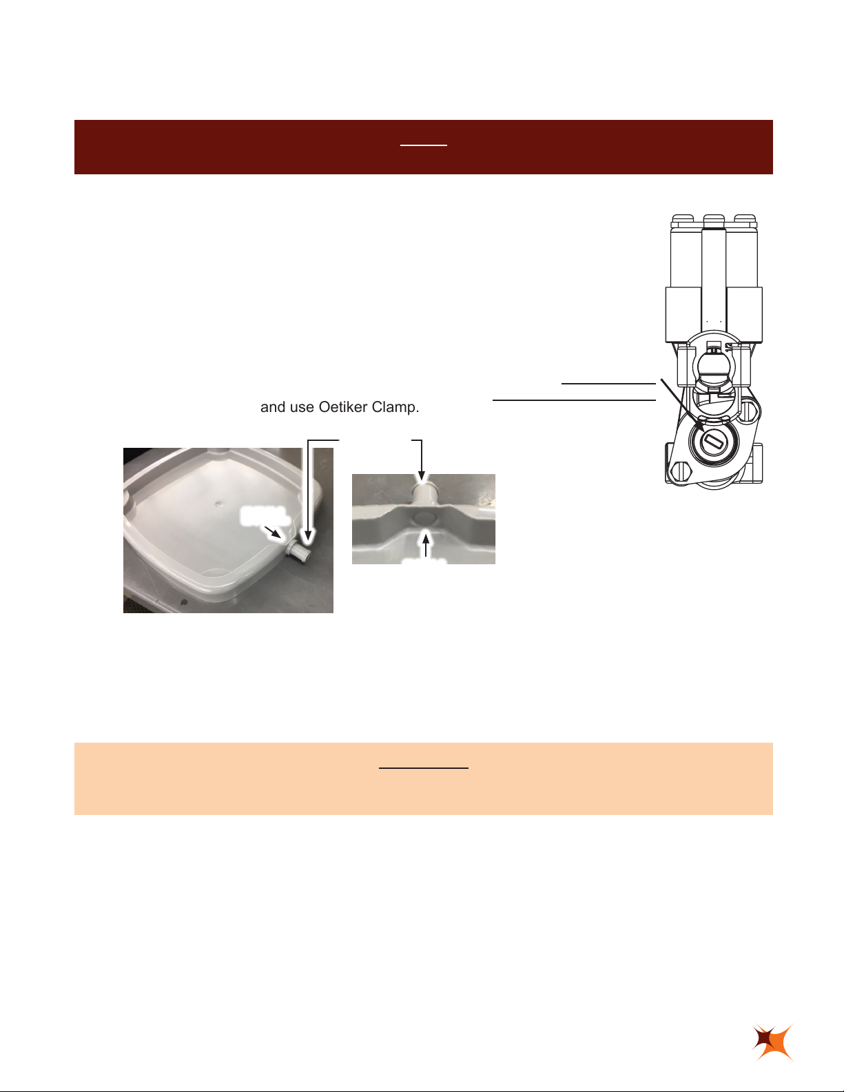
D. Daily Cleaning - Nozzle and Diffuser
1. Remove merchandiser by rst turning cam lock counter clockwise, then push down on the top
of the merchandiser while pulling outward, and nally up and out of bottom slots.
2. Remove nozzle by twisting clockwise and pull down. Diffuser is not removable.
3. Wash nozzle and diffuser with warm water. Ensure cleaning solution is rinsed off. Residual
Solution will cause product off taste.
4. Reinstall nozzle by twisting counterclockwise while pushing up.
5. Reinstall merchandiser.
NOTE:
Nozzle and diffuser must be sanitized biweekly. Ensure sanitary gloves are used for this procedure.
E. Biweekly Sanitizing - Nozzle and Diffuser
1. Prepare sanitizing solution:
Prepare a 100 PPM chlorine solution or other FDA approved sanitizer with clean potable
water at a temperature of 55˚ to 100˚ F (12.8˚ to 37.8˚ C).
Comparable strength: 1/2 uid oz. un-scented bleach in 1 gallon of water.
2. Remove merchandiser by pushing down on the top while pulling outward, then up and out.
3. Remove nozzle by twisting clockwise and pull down. Diffuser is not removable.
WARNING
DIFFUSER IS NOT REMOVABLE. ATTEMPTING TO REMOVE IT WILL DAMAGE DISPENSER.
4. Inspect nozzle for cracks or breakage.
5. Wash nozzle and immerse in a container of sanitizing solution for 15 minutes.
6. Wash diffuser with warm cleaning solution and inspect.
7. Wash diffuser and sanitize
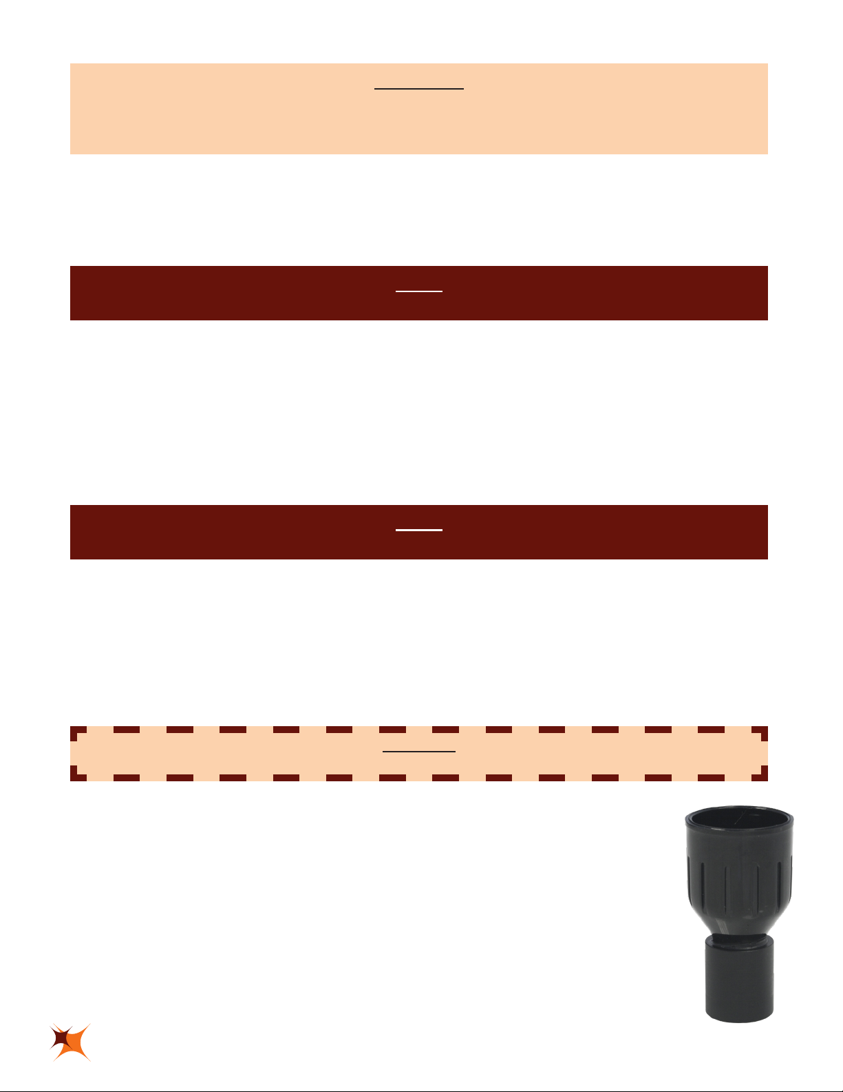
a. (OPTION 1) Use Nozzle Sanitizing Assy. (P.N. 631-0187) accessory:
Fill nozzle with sanitizing solution and install onto diffuser by twisting
counterclockwise while pushing up onto diffuser. Leave on for 15 minutes.
b. (OPTION 2) If Sanitizing Nozzle Assy. is not utilized, wash diffuser, rinse
and immerse in a sanitizing solution for 15 minutes.
8. While the parts are soaking, visually inspect around the nozzle mounting area
for syrup residue and wash area with cleaning solution.
9. Remove sanitizing nozzle from diffuser. Air Dry.
P.N. 631-0187

9
10. Remove nozzle from bath; air dry before re-installing onto diffuser.
11. Reinstall merchandiser.
F. Sanitizing Water Circuits:
Cleaning and Sanitizing are not required for potable water circuits. The potable water lines
should remain connected during the cleaning procedures for the concentrate circuits to avoid
contamination.
1. Disconnect concentrate container from product line.
2. Attach product line to container containing sanitizing solution mixed to mfg. recommendations
(100 ppm is recommended)
a. Using gray Shut-off, turn incoming water off.
NOTE:
Sanitizing solution temperature should be between 55˚ to 100˚ F (12.8˚ to 37.8˚ C).
3. Prepare enough solution to sanitize from the concentrate source to the dispenser.
NOTE:
OPTIONAL - using a tment removed from a bag in box container. Attach tment to concentrate
tting. Prepare sanitizing solution in a container and set tment/tting assembly in solution.
4. Push VALVES switch at rear of unit to the ON position.
5. Press appropriate switch position, solution will begin to ow towards dispensing valve.
6. When color turns clear, concentrate line is full of sanitizer solution.
7. Wait 15 minutes.
a. Reconnect concentrate product line.
8. Purge sanitizer from line with concentrate product.
9. Purge until concentrate is owing from dispensing valve.
10. Using gray Shut-off, turn incoming water on.
11. Taste the beverage to verify that there is no off taste.
12. Repeat for every product or as needed.
WARNING
FLUSH SANITIZING SOLUTION FROM CONCENTRATE LINE AS INSTRUCTED. RESIDUAL
SANITIZING SOLUTION LEFT IN SYSTEM COULD DAMAGE LINES AND DISPENSER PARTS.
IT MAY ALSO CREATE A HEALTH HAZARD.

10
7. TROUBLE SHOOTING
A. No water dispensed
• Check water supply
• Check Shut-off block knob (is it open)
• Check ratio/brix adjustment
• Line plugged
• Water regulator installed (65 PSI or less)
B. No syrup dispensed
• Check CO2pressure (55 psig +/- 5 psig)
• Check for product (BIB)
• Check Shut-off module knob
• Check ratio/brix adjustment
• Line plugged
C. Weak product taste
• Check ratio/brix adjustment
• Check for plugged line
• Check Shut-off module knob - completely open
• Check syrup supply
• Check target water pressure setting is 65 PSIG
D. Strong product taste
• Check ratio/brix adjustment
• Check syrup CO2
• Check water supply
• Check target water pressure setting is 65 PSIG
E. Merchandiser LEDs do not activate when LIGHTS switch is in ON position
• Light switch not activated
• Wire connections on LED may be loose
• AC/DC converter may be faulty (Replace)

11
8. TO REMOVE AND REPLACE THE PCB (PRINTED CIRCUIT BOARD) (P.N. 600-0013)
WARNING
DISCONNECT POWER FROM SUPPLY CIRCUIT BEFORE OPENING BACK PANEL.
A. Remove the lid, back panel and merchandiser from unit.
B. Disconnect the membrane switch and solenoid valves from the PCB. (Fig. 8.1 & 8.2)
C. Pinch the end point of the stand-off retainer (3 Places) to remove. (Fig. 8.3)
D. Slowly pull off PCB while pinching retainer. (Fig. 8.4)
E. PCB is now removed.
F. At this time, the PCB protective cover can be replaced if required. (Fig. 8.5)
G. Replacing PCB
1. Position wires between protective cover and PCB; line up holes on PCB with stand offs and
gently press in place. (Fig. 8.6)
2. Connect solenoid valves into the correlating position of the PCB. (Fig. 8.7)
3. Connect the membrane switch to PCB.
4. Replace unit back panel and lid.
Fig. 8.1 (Top of Unit) Fig. 8.2 (Top of Unit)
Fig. 8.3 (Top of Unit)
PINCH
PUSH
PUSH
Fig. 8.4 (Top of Unit)
Fig. 8.5 (Top of Unit) Fig. 8.6 (Top of Unit) Fig. 8.7 (Top of Unit)
1 2 3 4 5(water)

12
CUP REST
P.N. 661-0019
DRIP TRAY
P.N. 265-0752
INCLUDED ACCESSORIES
FLOW CONDITIONER NOZZLE
P.N. 265-0718
GROMMET, CAN, BLACK,
BLIND, TEA
P.N. 210-0030
1/4 BARB, W/ O-RINGS,
STAINLESS STEEL FITTING
P.N. 625-0004
CUP REST
P.N. 661-0019
DRIP TRAY
P.N. 631-0197

13
1/4 90 DEG, BARB, W/ O-RINGS,
STAINLESS STEEL FITTING
P.N. 625-0013
OPTIONAL ACCESSORIES
SHUT-OFF TOOL
P.N. 316-0005
SEPARATOR
P.N. 316-0004
DRAIN TUBING
P.N. 030-0017
NOZZLE ASSY, PLUGGED,
SANITIZING, 4FLVR TWR
P.N. 631-0187
KIT, COUNTER MOUNT
INSTALL, SCREWS
P.N. 690-0058
FLOW CONTROL TOOL
P.N. 316-0006
HOLE TEMPLATE

14
SHUT-OFF ASSEMBLY
1
2
3
4
6
8
9
10
11
12
5
7

15
SHUT-OFF ASSEMBLY
ITEM PART NO DESCRIPTION
1 319-1206 BRACKET ASSY, VALVES/BACK BLOCKS
2 220-0051 SCREW, 10-32 X 1”, PHILLIPS SLOT
3 637-0010 ASSY, VALVE, BACKBLOCK, SFCV
4 632-0192 WATER/SYRUP LINE ASSY
5 265-0043 WASHER, STEM
6 208-0109 O-RING, 2-109
7 265-0434 BODY, VALVE, MTG, SFCV
8 208-0110 O-RING, 2-110
9 265-0448 STEM, BODY, SFCV
10 256-0030 RETAINER, MTG B LCK, SFCV
11 224-0002 SCREW, 8-16 X .375, PLASTITE
12 247-0006 CLIP, RETAINER, MTG BLOCK

16
ASSEMBLY
1
2
3
4
5
6
3
8
9
7
10
11
12
13
14
15
17
18
19
20
22 23 3
24
25
26
27
29
30
31
32
33
34
3536
37
38
16
21
28

17
ASSEMBLY
ITEM PART NO DESCRIPTION
1 265-0751 MERCHANDISER, NCD GEN II
2 510-0031 CABLE EXTENSION, 17"
3 220-0005 SCREW, 8-32 X .375, PH, TH, SS
4 645-0497 LED PANEL ASSY, NCD, GEN II
5 265-0750 BACKSPLASH, NCD GEN II
6 631-0180 ASSY, ADAPTER NOZZLE, 4FE
7 632-0191 TUBE ASSY, VALVE TO NOZZLE, WATER, NCD GEN II, BLUE
8 224-0002 SCREW,8-16 X .375, PLASTITE, PHSL, PHD
9 632-0165 TUBE ASSY, VALVE TO NOZZLE, 9", SYRUP, 4FE
10 634-0234 WELDMENT, BODY, NCD GEN II
11 632-0192 ASSY, TUBE PRODUCT IN TO BACK BLOCK
12 625-0004 FTG, ASSY, .375 O-RING X .250 BARB
13 637-0010 ASSY, VALVE, BACKBLOCK, SFCV, GRAY
14 220-0051 SCREW, 10-32 X 1", PHILLIPS SLOT, TRIM RITE, SS
15 638-0008 VAVLE ASSY, SFCV, SYRUP, 1.5 OZ/SEC
16 638-0019 VALVE ASSY, SFCV, SODA/WATER, 2.0 OZ/SEC
17 634-0241 WELDMENT, LID, NCD GEN II
18 315-0048 CAM LATCH, SLOTTED
19 315-0043 COVER, PLASTIC SHEET, PC BOARD, 4FE
20 600-0013 PCB ASSY, 4 BUTTON DISPENSER
21 510-0032 CONTROLLER, LED 12V
22 601-0156 HARNESS ASSY, POWER SUPPLY-LED, NCD GEN II
23 319-1204 PANEL, BACK, REMOVABLE, NCD GEN II
24 210-0045 GROMMET, CAN, BACK, BLIND, TEA
25 505-0001 SWITCH, ROCKER, SPST
26 527-0007 POWER SUPPLY, 100-240 VAC C14 INPUT - 36 VDC OUTPUT, CLASS 2
27 670-0058 INSTALLATION TEMPLATE KIT
28 333-0006 BUMPER, GROMMET
29 319-1207 BRACKET, NOZZLE ASSY, NCD GEN II
30 365-0718 BODY, FLOW CONDITIONER NOZZLE
31 220-0004 SCREW, 8-32 X .500, PH, FH, SS
32 247-0001 CLIP, HITCH PIN, .250 DIA
33 215-0012 SPRING, CORE
34 278-0013 PIN, BUTTON, BACKSPLASH, GEN II
35 111-0003 OVERLAY, 2.0 X 7.5, 10MIL, POLY, NCD GEN II
36 526-0003 MEMBRANE SWITCH, NCD GEN II
37 661-0019 CUP REST, NCD GEN II
38 265-0752 DRIP TRAY, NCD GEN II

18
SYRUP & WATER VALVE ASSEMBLY
3456
1
4X
2
29
30
35
31
32
33
34
7
8
9
10
11
12
13
14
15
10
16
17
10 18
19
20
21
24
25
26
27
28
22
23

19
SYRUP & WATER VALVE ASSEMBLY
ITEM PART NO DESCRIPTION
1 638-0008 VALVE ASSY, SFCV, SYRUP, 1.5 OZ/SEC
2 638-0019 VALVE ASSY, SFCV, SODA/WATER, 2.0 OZ/SEC
3 808-0086 LABEL, S4, VALVE
4 808-0085 LABEL, S3, VALVE
5 808-0084 LABEL, S2, VALVE
6 808-0083 LABEL, S1 VALVE
7 SCREW, 8-16 X .500, PLASTITE, SL, HHD
8 RETAINER, BONNET
9 BONNET, BLACK
10 O-RING, 2-114
11 PLUG, ADJ, FC, RED
12 O-RING, 2-108
13 SPRING, SYRUP
14 PISTON, SYRUP
15 SLEEVE, WATER/SYRUP
16 BODY, VALVE, SFCV, BLACK
17 CLIP, RETAINER, SOLENOID, VLV
18 WASHER, SOLENOID, VALVE
19 SPRING, CORE
20 CORE ASSY, SOLENOID
21 COIL, SFCV
22 O-RING, 2-009
23 VALVE SEAT, POSTMIX VALVE
24 O-RING, 2-012
25 PLUG, NUT, SOLENOID
26 BONNET, SOLENOID, VALVE
27 RETAINER, SOLENOID
28 SCREW, 6-19 X .750, PLASTITE, PH, PHD
29 CAP, BONNET
30 808-0199 LABEL, WATER, VALVE
31 PLUG, ADJ, WATER, FC, WHITE
32 SPRING, SODA
33 PISTON, WATER, 4.5 OZ/SEC
34 SLEEVE, WATER/SYRUP, 4.5 OZ/SEC
35 BODY, VALVE, SFCV, NATURAL
Table of contents
Other Schroeder America Beverage Dispenser manuals
Popular Beverage Dispenser manuals by other brands

Cornelius
Cornelius VIPER 2 FLAVOR Service manual

Service Ideas
Service Ideas CBDT3SS Care and Handling

Elkay
Elkay smartwell SW1806CR installation manual

Wilbur Curtis Company
Wilbur Curtis Company TCC1 brochure

Silver King
Silver King SKMCD1P/C1 Routine Maintenance Tasks

Klarstein
Klarstein Hazzlehov Duett manual