Scorpio Miss Acro S2066 User manual

S2066 - Miss Acro
Technical data
WingSpan 1,380mm
Length 900mm
WingArea 25.6dm2
Weight 900g
WingLoading 35g/dm2
Radio 4 ch
Electric motor/Cells “400”(7/8Cells)
Introduction
CongratulationsonbuyingMissAcro,
thelatestdevelopmentofourpreviousMissMoravia.
Followingmany requests from delighted pilotsof Miss
Moravia,wehavenowaddedailerons toallow Miss
Acro to keep all of the best characteristics of Miss
Moraviaand in addition offerthemaneuverabilitythat
thesportpilot requires. The recent availability of small
brushlessmotorsoffers the ideal solution for the more
exuberantpilotswhilethe transparentfuselage
allows for easy inspection of the electronic parts at a
glanceandthe large canopy offers extraordinarily
easy access to all the equipment. Change the battery
really is a breeze on this model! Enjoy your Miss
Acro!
Before starting construction
Carefully study the building Instructions as well
as the assembly sketches: it is time well spent.
Check off each construction step as you complete it
so that if work is interrupted you’ll be able to resume
where you left off. A bracket [ ] is placed next to each
buildingstageforthispurpose.
Checking the kit
[ ] Examine the kit to ensure nothing is missing.
[ ] Removeeachdiecutpart and sand carefully
whererequired.
Equipment needed
Here’s all you need to build your Miss Acro:
[ ] Modellingknife
[ ] Scissors
[ ] Sandingblockwithcoarseand fine paper
[ ] Setsquare
[ ] Drill with a 2 and 3 mm bit
[ ] Adhesivetape
[ ] Roundfile5mmdiameter
[ ] Some black enamel paint
[ ] 5 minute Epoxy or Cyanoacrylate Glue
Wing assembly
W-1 [ ] Using a knife with a sharp blade, trim the
coveringfilmfromthewingrootrib.Leavejustavery
narrowoverlapof film. Do not allow this overlap to
come away from the root rib, if it does come loose
use a film iron to iron back into place.
W-2 [ ] Carefully cut out the aperture for the aileron
servointheright wing panel [2]. Repeat the operation
on the left wing panel [3].
W-3 [ ] Insert the wooden dowel [B3-8] into the right
wing[2],before offering this wing panel to the leftwing
[3]. Before gluing check that all the parts fit
accuratelytogether.Ifnecessary,sand the dowel or
open up the bore of the hole. Check also for the
correct alignment of the two wings. After the glue has
been applied but before it has cured, check that the
wing’s dihedral is as required (85 mm) Use a book or
block of wood under the raised panel to set the
requireddihedral,then fill any minor gaps between
them with glue.

Miss Acro S2066
W-4 [ ] Using a sharp knife cut through the covering
filmon the forward side of thedihedralbrace slot.
Peeling the film back will allow the dihedral braces
[DC3-1]to be fitted.
W-5 [ ] Glue together the dihedral braces [DC3-1].
Check that the assembled brace fits the wing slot.
Sandcarefullyif required to obtain a perfect fit.Glue
brace into position and smooth down the film flap to
coverthe brace.
Fuselage and Tailplane Assembly
F-1 [ ] Drill two 3mm holes through the bottom of the
fuselage[1],inthecorner between the main former
andthefuselagesides.
F-2 [ ] Carefully cut open the slot for the main
undercarriage[7].
F-3 [ ] Gluethe upper half-former[B3-2]onto the
mainfuselage former.
F-4 [ ] Insert the main undercarriage [7] into the
fuselageslot. Now glue the doubler [B3-1] ontothe
upperhalf-former[B3-2].Insert and glue into place the
undercarriagesecuring plate [B3-3].
F-5 [ ] Before the glue is dry, check that the
undercarriageiscorrectlyalignedwiththefuselage.
Adjust as necessary.
F-6 [ ] If necessary use a small file to clean up the
endsof the undercarriage legs[7] then fit the inner
lock washer [B2-2], the wheel [B2-1] and the other
lock washer [B2-2], ensuring that the wheel [B2-1]
runsfreely.
F-7 [ ] Glue the fuselage doublers [8] into position
insidethefuselagetogether with the spacers [DC2-4].
F-8 [ ] Glue in position the radio and servo
tray[DC2-1]andthepushrodsupport[DC2-
2] keeping the slots for the pushrods toward
the top.
F-9 [ ] Glue in position the former [DC1-2]
F-10[ ] Remove the covering film over theslot for the
tail skid [DC1-5]. Glue the tail skid [DC1-5] into
position on the fuselage. Glue the wire skid [B2-3]
overthetail skid [DC1-5].
F-11[ ] Remove the covering film over theslot for the
fin [4] in the tailplane [5].
F-12 [ ] Hold the tailplane [5] in place on the fuselage
and use a pen to mark its position. Leave a gap of
approximately2mmbetweenthefrontofthetailplane
andthefront of the tailplane mount.
F-13 [ ] Use a sharp knife and carefully cut through
thecoveringfilm along the marked line before
removing the waste film. Ensure that only the film is
cut, not the tailplane structure. Cut around 1 mm
insidethemarkedlinestoavoidbarewoodshowing
through.
F-14 [ ] Glue the fin [4] into place on the tailplane [5]
F-15 [ ] Before the glue is completely dry, check with
a square that the tailplane [5] and fin [4] are perfectly
square.Adjust as necessary.
F-16 [ ] Glue the complete tail assembly to the
fuselage.
F-17 [ ] Use a square to check the alignment of the
tail assembly to the fuselage before the glue has
completelycured.
F-18 [ ] Glue in place the fuselage brace [B3-4]
F-19 [ ] Cutaway the covering filmoverthe holes for
the wing dowels [B3-7]. Insert the dowels [B3-7]
applying some glue to the dowels inside the fuselage.
F-20 [ ] Glue in position the two canopy attachment
hooks [DC1-3]. To accurately position these hooks
usethecanopyframe [DC1-1] positioned over the
fuselage.Theframemustbefreetoslid from under
the hooks.
F-21 [ ] Gluetogether the canopy frame[DC1-1]and
the canopy catch [DC2-3] along with its spacer [DC1-
4].
F-22 [ ] With scissors cut away excess material from
thecanopymoulding[6] following the
mouldedcutline, leaving a couple of mm ofmaterial
thatwill removed later.
F-23 [ ] Paint the inside of the canopy with black
paint, as per the boxtop image. Position the canopy
frame [DC1-1] inside the canopy [6] and glue it in
position. When the glue has cured, trim the excess
canopymaterialaway carefully.The canopycatch
protrudesbehindthe canopy.
F-24 [ ] To mount the canopy [6] to the fuselage you
have first to insert the canopy catch tongue under the

S2066 Miss Acro
top of the fuselage, inside the canopy hatch. Then
slightly tilt the canopy to engage the
attachmenthooks.Theplywoodtonguewillbend
easily and allow the canopy to be slid into position.
To remove thecanopyreverse the procedure.
Radio Installation
RC-1 [ ] Position the two servos on the servo
support[DC2-2] and mark the position ofthe
mountingscrews. (notsupplied).Removetheservos
and with a 1.5 mm bit drill the holes for the mounting
screws.
RC-2 [ ] Cut out the film over the control cable slots
intherearendofthe fuselage. Insert the elevator tube
[B1-2]andthe rudder tube [B1-4] into the fuselage
slots letting them extend from the fuselage sides by
about 10 mm, then epoxy them in place.
RC-3 [ ] Punch through the film over the holes in the
rudder for the control horn [B1-7] and install it in
position on the rudder. Secure in position using nuts
[B1-8].
RC-4 [ ] Repeatthe above procedure and fit the
elevatorcontrol horn [B1-7].
RC-5 [ ] Install the servos in the servo tray [DC2-1],
connect them to the Rx and ensure they are
centered.Removethe servo arms and insert the “Z”
endofthepushrods [B1-1] and [B1-3] respectively
from above and into the central holes in the arms.
Slide the pushrods [B1-1] and [B1-3] into the tubes
[B1-2] and [1-4] until it is possible to install the servo
output arms onto the servos in the neutral position.
Gluetherudderand elevator tubes [B1-2] and [B1-4]
tothepushrodsupport[DC2-2]
RC-6 [ ] Screw the threaded adapter [B1-5] to the
snap link [B1-6]. Connect the snap link to the elevator
control horn [B1-7] in the middle hole. Fit the
threadedadapterontothe end of the pushrod and
check the length of the pushrod [B1-1] keeping the
elevatorattheneutral position and the servo
centered.Ifnecessary, shorten the pushrod [B1-1]
cutting it down to the correct length. When servo and
elevatorareaccuratelyaligned,epoxyorsolderthe
pushrod[B1-1]intotheadapter [B1-5].To improve the
joint, use pliers to slightly bend the end of the
pushrod to ensure it fits tightly inside the adapter.
RC-7 [ ] Repeat the above procedure to connectthe
ruddersurface to the rudder servo. Again carefully
checkthealignmentoftheservo arm and rudder horn.
RC-8 [ ] Mark the position of the trailing edge
doublers[DC5-1]. They must be positioned so that
the inner edge is 25 mm from the centre of the wing.
Slide the doubler back by 2mm then cut through the
coveringfilm around the edge ofthedoubler.
RC-9 [ ] Glue the doublers [DC5-1] into place,
makingsuretheedges of the film are trapped under
thedoubler.
RC-10 [ ] Usea sharpknife and remove the film
abovetheslots for the aileron torque rods [B1-9] on
boththewing and the aileron. Also removethefilm
abovethe servobay.
RC-11 [ ] Insert the aileron torque rods into the wing
slot and carefully glue the plastic tube in position.
Ensure that no glue is allowed to get into the plastic
torquetubeandensurethatthetorquerod can move
freely.
RC-12 [ ] Assemble the aileron servo tray.
RC-13 [ ] Position the aileron servo on the tray and
markfortheservo screws. Remove the servo and drill
1.5 mm holes for the servo screws.
RC-14 [ ] Glue the aileron servo tray into place.
RC-15 [ ] Screw the aileron servo into place on the
tray.
RC-16 [ ] Screw the torque rod connectors [B1-11] on
to the aileron torque rods, threading them on so that
2mmofthreadappears above the connectors. Screw
the clevis [B1-6] on to the pushrod [B1-11] and insert
the”Z”end into the servo arm. With theservocentred
ensure that the aileron is correctly aligned with the
wing section. Adjust the clevis [B1-6] as required.
Repeatforthe second aileron pushrod.
Installing the Motor
Thereare manydifferentgearboxes availablefor400
size electric motors. We have illustrated the most
common type. Below you’ll find also some information
forfittingalternativeunits.
MPJet or similar gearboxes
MPJ-1 [ ] Installation of the MP Jet gearbox requires
theuseof gearbox adapter,partnumber M-EP4MGX,
which is available separately. It is also necessary to

Miss Acro S2066
removethe unused gearbox “ears” from the gearbox.
MPJ-2[ ] Measurethedistance between the holes for
themountingscrews(not supplied) on the adapter.
Mark this dimension on the front bulkhead of the
fuselageanddrill 3mm holes for the mounting screws.
MPJ-3 [ ] Screw the motor/gearbox assembly into
place.
MPJ-4 [ ] The output shaft of the gearbox should
haveabout5°ofdownthrustand2° of sidethrust. Use
ply shims to adjust as required.
Horak and similar gearboxes
MH-1 [ ] Assemble the motor cradle gluing
together its parts.
MH-2 [ ] Put the motor cradle into the forward part
of the fuselage, add the motor and check for the
alignment of the motor shaft with the hole in the
fuselagefrontformer. When the alignment iscorrect,
epoxy the cradle into the fuselage.
MH-3 [ ] Fasten the motor to its cradle using a
plastic tie strap.
MH-4 [ ] Glue the mounting plate into place so
that the output shaft of the gearbox is central to the
hole in the nose of the fuselage.
MA-5 [ ] Screw the motor/gearbox into place, and
attachthe propeller.
Finishing
FT-1 [ ] Recommendedlayoutofradio and drive
system in Miss Acro.
FT-2 [ ] Electronic schematic of the parts installed
in Miss Acro.
FT-3 [ ] Check that the control surface movements
arecorrect. The elevator movementshouldbeabout
20°upanddown.Ruddershouldbeabout30°leftand
rightandaileronsabout 20° both directions.
FT-4 [ ] Add the supplied decals to the model as per
the box illustration.
FT-4[ ] Check the balance point. It must be between
55 and 60 mm back from the leading edge of the
wing. If necessary, move the batteries inside the
fuselageto balance.
Safety Warning!
YourMissAcro isarelatively
safe R/C model. It may be flown in fairly small areas
withoutdisturbingyour neighbours. Never forget that it
is not a toy and that it could be potentially dangerous
if common sense is not used. Avoid flying in
populatedareas or close to roads,railways, airports
and so on. Ensure that any spectators are aware of
thepotentialdangerofyourmodel.
Enjoyflying your Miss Acro!
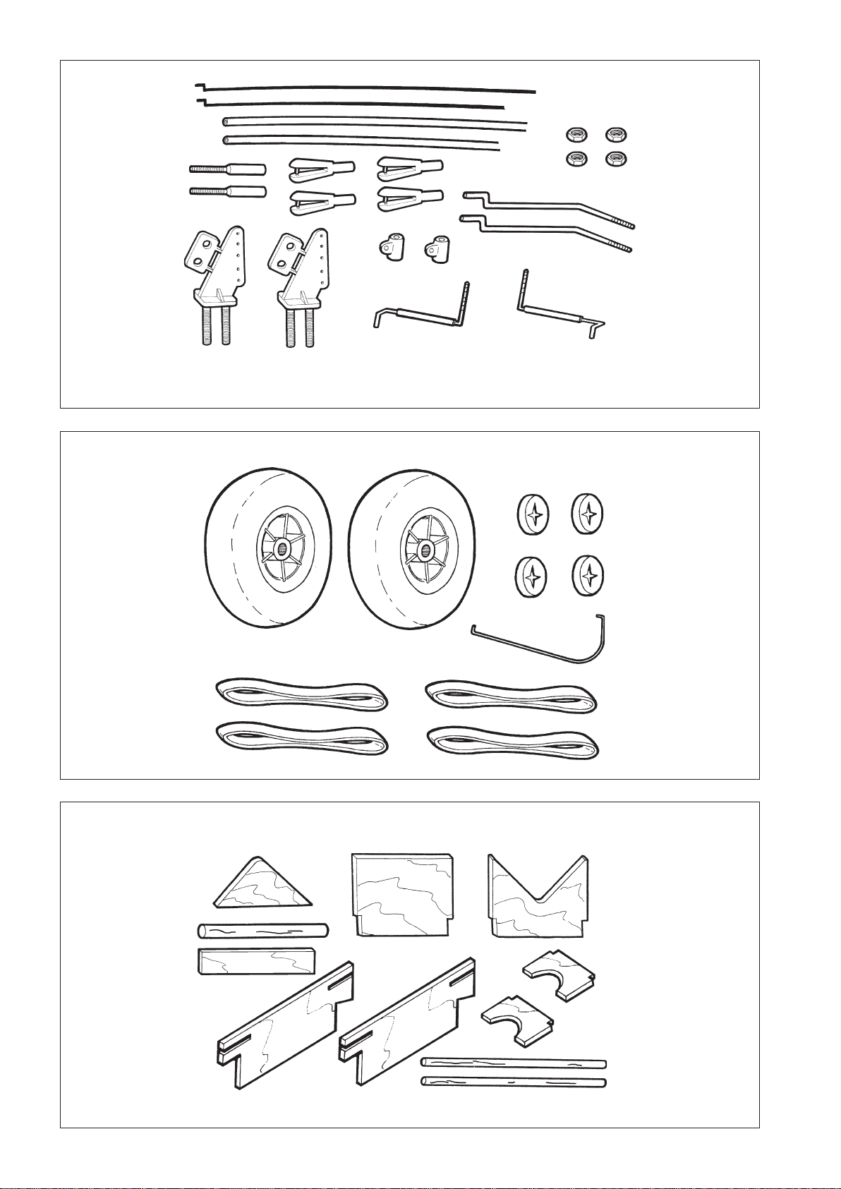
Box Parts
No. Qty. Description
[1] 1 Fuselage
[2] 1 Right Wing
[3] 1 Left Wing
[4] 1 Ruddercomplete
[5] 1 Tailplane complete
[6] 1 Canopy
[7] 1 MainLandingGear
[8] 2 Fuselage doublers
1 BagB1
1 BagB2
1 BagB3
1 DieCutDC-1
1 DieCutDC-2
1 DieCutDC-3
1 DieCutDC-4
1 DieCutDC-5
1 Decals
1 InstructionBooklet

W-1 W-2
W-3 W-4
W-5 F-1
F-2 F-3
[3]
[3]
[3]
[2]
[B3-8]
[DC3-1]
[1]
[B3-2]
[1]
[1]

F-4 F-5
F-6 F-7
F-8 F-9
F-10 F-11
[B3-3] [7]
[1]
[7]
[B2-2]
[B2-1]
[B2-2]
[8]
[DC2-4]
[DC2-2]
[DC2-1] [DC1-2]
[DC1-5]
[B2-3]
[5]
[B3-1]

F-12 F-13
F-14 F-15
F-16 F-17
F-18 F-19
[5]
[5]
[1]
[4]
[5]
[4]
[5]
[1]
[B3-4]
[1]
[B3-7]
[B3-1]

F-20 F-21
F-22 F-23
F-24 RC-1
RC-2 RC-3
[DC1-3]
[DC1-4]
[DC2-3]
[6]
[DC1-1]
[B1-2] [B1-8]
[B1-7]
[DC1-1]

RC-4 RC-5
RC-6 RC-7
RC-8 RC-9
RC-11RC-10
[B1-1]
[B1-7]
[B1-8]
[B1-5] [B1-6]
[B1-6]
[B1-5]
[B1-3] [B1-5] [B1-6]
[B1-4]
[DC5-1] [DC5-1]
[B1-9]

RC-12 RC-13
RC-14 RC-15
RC-16 MPJ-1
MPJ-2 MPJ-3
[B3-6]
[B3-5]
[B1-11]
[B1-10]
[B1-6]

MH-1 MH-2
MH-3 FT-1
FT-2 FT-3
FT-4 FT-5
[DC4-3] [DC4-4]
[DC4-1]
[DC4-2]
[B1]
[B3]
[B2]
[B1-1]
[B1-3]
[B1-2]
[B1-4]
[B1-8]
[B1-5] [B1-6]
[B1-11]
[B1-7] [B1-9]
[B1-10]
[B2-2]
[B3-1]
[B2-3]
[B2-4]
[B2-1]
[B3-2]
[B3-3]
[B3-6]
[B3-4]
[B3-5]
[B3-8]
[B3-7]

[DC1]
[DC2]
[DC3]
[DC5]
[DC1-5]
[DC1-1]
[DC1-2]
[DC1-3]
[DC1-4]
[DC2-3]
[DC2-1]
[DC2-2]
[DC2-4]
[DC3-1]
[DC3-1]
[DC5-1]
[DC4-2]
[DC4-1]
[DC4-3]
[DC4-4] [DC4]

Miss Acro S2066
Bag [B2]
No. Qty. Description
[B2-1] 2 Wheel
[B2-2] 4 Wheel Lock
[B2-3] 1 Tail Skid
[B3-3] 4 RubberBands
Die Cut [DC-3]
No. Qty. Description
[DC3-1] 2 Wing joiner
Die Cut [DC-4]
No. Qty. Description
[DC4-1] 1 Motor cradlerearformer
[DC4-2] 1 Motor cradle front former
[DC4-3] 1 Motor cradle front former
doubler
[DC4-4] 2 Motor cradle side
Die Cut [DC-2]
No. Qty. Description
[DC2-1] 1 Radio and servo tray
[DC2-2] 1 Pushrod support
[DC2-3] 1 Canopy catch
[DC2-4] 2 Fuselage longeronspacer
Bag [B1]
No. Qty. Description
[B1-1] 1 Pushrod
[B1-2] 1 Pushrod
[B1-3] 1 Tube
[B1-4] 1 Tube
[B1-5] 2 ThreadedAdapter
[B1-6] 4 Snap Link
[B1-7] 2 ControlHorn
[B1-8] 4 Nuts
[B1-9] 2 Torque rod
[B1-10] 2 Torque RodConnector
[B1-11] 2 Pushrod
Bag [B3]
No. Qty. Description
[B3-1] 1 Semi-former
[B3-2] 1 Doubler
[B3-3] 1 GearLock
[B3-4] 1 FuselageBrace
[B3-5] 2 WingServo Cradle Side
[B3-6] 2 WingServo Cradle Joiner
[B3-7] 2 WingDowel
[B3-8] 1 WingJoining Dowel
Die Cut [DC-1]
No. Qty. Description
[DC1-1] 1 Canopyframe
[DC1-2] 1 Fuselageformer
[DC1-3] 2 Canopy hooks
[DC1-4] 1 Spacer
[DC1-5] 1 Tail skid
Die Cut [DC-5]
No. Qty. Description
[DC5-1] 2 TrailingEdgeDoubler

S2066 Miss Acro
Notes:

Table of contents
Other Scorpio Toy manuals


Popular Toy manuals by other brands

Tyco R/C
Tyco R/C R3044-0920 instructions

Sky Master
Sky Master ARF PLUS PRO HAWK 100 Assembly and operation manual

V-tech
V-tech Go! Go! Cory Carson DJ Train Trax & the Roll... Parents' guide

Hot Wheels
Hot Wheels CONSTRUCTION ZONE CHAOS instructions

V-tech
V-tech Switch & Go Stegosaurus Buggy Parents' guide

V-tech
V-tech Kidizoom camera Connect user manual

V-tech
V-tech Hover Pup instruction manual

J. Perkins
J. Perkins Twister CP V2.1 manual

V-tech
V-tech SWITCH & GO DINOS Turmoil the Triceratops Parents' guide

Best Choice Products
Best Choice Products SKY3895 instruction manual

V-tech
V-tech 3-in-1 Smart Wheels user manual

Hobby King
Hobby King Electrolyte Assembly manual


