Scorpio Palio pro User manual

Palio pro S2084
Technical data
Wing span: 2150 mm
Lenght: 1150 mm
Weight: 1120 g – 1860 g
Wing area: 42 dm2
Wing loading: 27 g/dm2 – 44 g/dm2
El. Motor/ no. of cells: „600“ / 7-8 cells
Controls: Elevator, rudder, motor
Introduction
Congratulations on buying your Palio-pro. Since most
of the building work has already been done you’ll invest
just a small amount of time in building and you’ll enjoy
getting in the air quickly. As a glider this is an excellent
thermic model with high efficiency characteristics and
as an electric powered model (optional) it is at the level
of the best competitors in its category.
Your Palio-pro flys well with a direct drive electric motor
and standard 7 cell power pack. However with a gear
drive unit and higher output 8 cell pack its best flight
characteristics may be reached. Its excellent Astra©
epoxy fuselage is a great investment for a durable,
robust and light fuselage. Enjoy it!
Before starting construction
Carefully study the exploded view as well as the building
sketches; read and understand the step by step
instructions before beginning construction, it is time
well spent. First, examine the kit to ensure nothing is
missing. Using the illustrations mark each wood part
with its corresponding number. Remove each die cut
part and sand it carefully.
Although the assembly of the model is not complicated,
it is important to carefully study the assembly
instructions and think over each step thoroughly
Equipment needed
Here’s all you need to build your Palio-pro:
- Modeling knife
- Scissors
- Sanding block and coarse, medium and fine
sandpaper
- Square
- Drill and a 1.5, 2 and 3 mm bit
- Masking tape
- Solder
- 5 minute Epoxy Glue and/or Cyanoacrylate
- Hobby saw
Glider or Electro Glider?
Your Palio-pro is a very versatile model. It can be
successfully flown as a tow line glider or as an electric
motor glider.
If you are building the tow line version disregard steps
3 to 5. For the electric powered version disregard steps
1 and 2.
Assembly:
1. (Glider only) Glue (Epoxy) the towing hook supports
[DC-1] together. Next glue towing hook supports in place
inside the fuselage [1] about 330 mm from the nose.
2. (Glider only) With a drilling machine and a 2 mm bit,
drill a hole in the middle of the fuselage bottom at about
360 mm from the nose. Screw the tow hook [B2-5] to
the fuselage.
3. (Electro glider only) Following the cut line on the
fuselage nose, remove the nose with a hand saw. It is
better to leave some material and remove it afterward
with a sanding block.
4. (Electro glider only) Glue (Epoxy) together the two
motor formers [DC-2]
5. (Electro glider only) With a 3 mm bit drill the two
holes for the motor fastening screws[ B2-6]. Fasten the
electric motor to the formers [DC-2] with the two screws[
B2-6]. Check the motor matches the center hole. Glue
(Epoxy) the motor support in place inside the fuselage
nose. Check that the motor matches the spinner and
that the alignment of the motor shaft is precise.
6. Glue (Epoxy) in place the brass tube [B2-1] inserting
it first over the wing joiner [B1-5] and then inserting both
of them into the fuselage’s holes. Looking at the
fuselage from the front, check the alignment of the wing
joiner rod which has to be perpendicular to the fin.
7. Check also that the brass tube [B2-1] is flush with the
outer surface on both sides of the fuselage. If necessary,
use a sanding block, to remove any tubing.
8. Assemble (Epoxy, CA) the plywood cradle made of
the parts [DC-3], [DC-4], [DC-5] and [DC-6].
9. With a 2 mm bit drill the holes for the servo and switch
mounting screws.
10 - Insert the assembled cradle into the fuselage and
glue (Epoxy) it in position about 130 mm from the
fuselage nose.
11. With a 3 mm bit carefully drill the exit holes for the
rudder and elevator’s linkage.
12. Cuttwoslotsontheverticalfinfortherudder’shinges
[B2-13]. Check the position with the rudder’s pre-cut
slots.
13. Glue (Epoxy, CA) the rudder’s hinges [B2-13] to the
fin and to the rudder [3]. Check that the rudder’s
movement is free and that the rudder and fin are not
glued together.

14. Glue (Epoxy) the tailplane steel joiner [B2-14] into the
fuselage’s fin. Check that it is perpendicular both to the fin
and to the length of the fuselage.
15. With a sharpen balsa cutter cut out the covering film over the
hole of the left horizontal tailplane [4]. Insert into the hole of the
tailplane [4] the fastening connector [B2-15] and insert also the
connecting rod [B2-2] into their holes. Fasten the connecting
rod [B2-2] to the connector [B2-15] with the screw [B2-11].
16. Glue (CA, Epoxy) the connector [B2-15] to the tailplane.
Take care to avoid that some glue is also gluing the
connecting rod. Glue has to be put only on the connector’s
sides and very sparingly.
17. When the glue has cured it is possible to release the
connecting rod loosening the screw [B2-11].
18. Insert the auxiliary tailplane connecting rod [B2-2] into
the hole of the right tailplane [4] and glue (Epoxy) it in place
leaving outside about 50 mm. Fit the elevator control horn
[B2-7] into the holes in the elevator by punching the film over
the holes and inserting the control horn [B2-7] into the holes.
Fasten the control horn with two nuts [B2-8].
19. Insert the rudder outer tubing [B1-3] and the elevator outer
tubing [B1-4] into the exit holes of the fuselage and carefully
glue (Epoxy) it in place leaving a couple of cm extending from
the fuselage.
20. Fit the rudder control horn [B2-7] into the holes in the
rudder [3] by punching the film over the holes and inserting
the control horn [B2-7] into the holes. Fasten the control horn
with two nuts [B2-8].
21. Fasten the servos on their support with their screws (not
supplied)
22. Note that the pushrods cross inside the fuselage to give
a straight pushrod run. Switch on the radio and position both
the servos at their centre positions. Insert the rudder and
elevator pushrods [B1-1], [B1-2] in the plastic tubes [B1-3],
[B1-4]. Insert the Z bent ends of the pushrods into the servo
arms. Fit the servo arms to the servos ensuring they are
centred correctly.
23. Glue (Epoxy) the plastic tubes holders [B2-4] to the
fuselage sides and next glue (Epoxy) the plastic tubes [B1-3]
and [B1-4] to the groove in the holders and to the slots in the
former [DC-5].
24. Attach the kwick link [B2-10] to the middle hole in the
rudder control horn [B2-7]. Insert the end of the pushrod into
the threaded adapter [B2-9] and check the length of the
pushrod [B1-1] keeping both the rudder and the servo
centered. If necessary, shorten the pushrod [B1-1].
25. Whenthepushrod[B1-1]isthecorrectlength,glue(Epoxy)
or solder the pushrod [B1-1] into the threaded adapter [B2-
9]. To improve the join, use pliers to kink the end of the
pushrod to fit tightly in the adapter.
26. Complete the elevator with the fuselage and repeat the
point 24 – 25 to install the linkage.
27. The inner and outer wing panels [2] are covered together.
With a knife carefully cut away the covering film over the gap
between the two wing panels, on the upper side of the wing
only. Remove the excess film and the triangular packing strip
that you’ll find inside the slot. Do not cut the film on the bottom
of the wing.
28. Carefully apply some glue (Epoxy) in the slot between the
two wing panels. Put the wing flat over a desk and raise the
tip of the outer panel about 110 mm. Check to ensure the two
panels fit together without any large gaps at the joint.
29. With a sharp blade cut off the film over the holes for the
fastening screws, on the top of the wings [2].
30. Take the brass wing fastening insert [B2-12] and screw
temporary inside it the screw [B2-17]. Put some amount of
epoxy in the outer surface of the insert [B2-12] and inside the
wing’s hole. Using a screwdriver gently screw the assembly
into the wing. Allow the resin to cure and then remove the
screw [B2-17] by unscrewing it.
31. Using the sanding block round the edges on the both
sides of the steel wing joiner [B1-5]. See the drawing.
32. Using the sanding block round one of each wing dowels
[B2-3]. Attach the the wing dowels to the wing, next attach the
wing to the fuselage using the wing joiner [B1-5] and check
the correct position of the wood wing dowels [B2-3]. Now
carrefully glue (Epoxy) the wing dowels [B2-3] in the holes on
the both wings [2]. Check the correct position of the wings.
33. Attach the wings to the fuselage and check the alignment.
Fasten the steel wing joiner with screws [B2-11] using the
special allen wrench [B2-16].
34. With scissors, trim the canopy [5] along the outer line,
keeping a safety margin of about 1 or 2 mm. Sand the edges
of the canopy to fit the canopy to the fuselage.
35. Secure the canopy [5] with masking tape to the fuselage.
Drill two 1.5 mm holes at about 4 mm from the canopy rim
forward and rearward. With the sharp kniwe cut out two slots
intothe canopy [5]inorder to extractthecanopy by just pushing
on it. This will allow the canopy to be removed without
unscrewing the fastening screws[ B2-8]
36. Refer to the drawing for a recommended arrangement of
equipment. You may lead the receiver aerial out either from
the top of fuselage behind the canopy to the fin.
37. When connecting electronic equipment, follow the
instructions supplied.
38. Use the details shown check the throw and direction of
the control surfaces. If necessary, change the position of
control rods on the servo control horns or control surface
horns.
39. If you have not applied all decals during the assembly,
now is the right moment to do so.
40. Check the centre of gravity (CG) position with batteries in
place. It should lie 70 - 75 mm back from the wing leading
Palio pro S2084

edge. For first flights it is recommended that the balance
point be at the forward position. Once the motor, speed
controller and receiver are installed, the battery pack can be
attached to the battery mounting plate using hook and loop
tape or similar. The battery pack can still be moved forward
or back on the battery mounting plate to allow minor changes
of the balance point. Add ballast to balance the model if
necessary.
Flying the model.
The initial flights should take place in a complete calm or in
a very light breeze. Long grass is an advantage. Check the
model (wings, tail surfaces etc.), CG position, throw and
sense of deflection of the control surfaces and for smooth
operation of the motor / gearbox. Launch the model
horizontally or into a slight climb into wind, with the motor
running at full power. Allow the model to climb to a safe height,
reduce the throttle slightly and trim the model. Check the
response of the model to the control inputs. If your model
does not handle correctly, switch off the motor and land. If
you are a complete novice, ask a more experienced modeller
for assistance.
We wish you many successful flights and happy landings.
Warning!
This aircraft is designed to give you many enjoyable flights,
however if you exceed the specifications of the aircraft by
using a more powerful electric motor or more than 8 cells
you may compromise the structural integrity of the aircraft.
Keep in mind that good sense is always necessary for safe
modeling and safe flying.
The following parts are necessary to finish the model but
are not included in the kit:
- A SPEED „600“ electric motor with spinner and folding
propeller, S8025s 25A speed controller
- 2 standard servos
- Batteries 1200 - 3000 mAh, 7-8 cells,
- Battery charger
- RC system, minimum 2/3 channels
Content of the kit
No. Description Qty
1 Fuselage 1
2 Wing 2
3 Rudder 1
4 Tailplane 2
5 Canopy 1
Bag B1 1
Bag B2 1
Die cut DC1 1
Instruction manual 1
Decal sheet 1
Bag B1
No. Description Qty
B1-1 Rudder pushrod 1
B1-2 Elevator pushrod 1
B1-3 Rudder plastic tube 1
B1-4 Elevator plastic tube 1
B1-5 Steel wing joiner 1
Bag B2
No. Description Qty
B2-1 Brass tube 1
B2-2 Tailplane Auxiliary Rod 1
B2-3 Wood wing dowel 2
B2-4 Linkage holder 2
B2-5 Tow hook 1
B2-6 Motor screw 2
B2-7 Control horn 2
B2-8 Control horn nuts 4
B2-9 Linkage threaded adapter 2
B2-10 Kwick link 2
B2-11 Allen screw 3
B2-12 Tailplane fastener insert 1
B2-13 Nylon hinge 2
B2-14 Tailplane main rod 1
B2-15 Wing fastener insert 2
B2-16 Special allen wrench 1
B2-17 Temporary screw 2
Die cut DC1
No. Description Qty
DC-1 Tow Hook Support 2
DC-2 Electric Motor Former 2
DC-3 Servo Support 1
DC-4 Servo Support Forward Former 1
DC-5 Servo Support Rearward Former 1
DC-6 Former Triangular Support 4
S2084 Palio pro

12
34
56
7
[B2 - 1]
[B2 - 5]
360 mm
1,5 mm
330 mm
[DC - 1]
[1]
[1]
[1]
[1]
[DC - 3]
[DC - 4]
[DC - 6]
[DC - 5]
8
[DC - 2]
[DC - 2]
[1]
[1]

910
11 12
13 14
15 16
[1]
[B2 - 11]
[1]
90°
[4]
[4]
[1]
[3]
90°
[B2 - 2]
[B2 - 15]
[1]
[1]
[DC - 3]
130 mm
[DC - 3]
[B2 - 13]
[B2 - 14]

17 18
19 20
21 22
24
[1]
[4]
[B2 - 8]
[B2 - 7]
50 mm
[B2 - 10]
[B2 - 9]
[B2 - 7][B2 - 1]
[B1 - 3]
[B1 - 1]
[B1 - 3]
[B2 - 7]
[B2 - 8]
[1]
[1]
[1]
[B1 - 3]
[3]
23
[B2 - 1]
[B2 - 4]
[1]

26
27 28
29 30
31 32
110 mm
[B2 - 12]
[2]
[2]
[2]
[2]
[2]
[B2 - 2]
[B2 - 14]
[4]
[4]
[1]
25
[1]
[B2 - 17]
[B1 - 5]
[B2 - 3]
[2a]

33 34
35 36
[5]
[B1 - 5]
90°
[B2 - 11]
[2]
[5]
1,5 mm
[1]
S
30°
Rec
Accu
30°
10°10°
70 - 75 mm
0°
+2,5 °
Rec
Reg S
M
39
38
37
[B2 - 16]
40
MReg S
S
Rec
Accu
[B2 - 6]
[B2 - 6]

B2
B1
[B2 - 8]
[B2 - 4]
[B2 - 16]
[B2 - 5]
[B2 - 13]
[B2 - 3]
[B2 - 6]
[B2 - 1]
[B2 - 7]
[B2 - 9]
[B2 - 10] [B2 - 15]
[B2 - 12]
[B1 - 1]
[B1 - 3]
[B2 - 2]
[B2 - 14]
[B1 - 4]
[B2 - 11]
[B1 - 2]
[B1 - 5]
[4]
[1]
[5]
[2]
[3]
[B2 - 17]
[2a]
[2a]

DC
[DC - 5]
[DC - 2]
[DC - 1] [DC - 1]
[DC - 2]
[DC - 4]
[DC - 6]
[DC - 3]

Other Scorpio Toy manuals
Popular Toy manuals by other brands
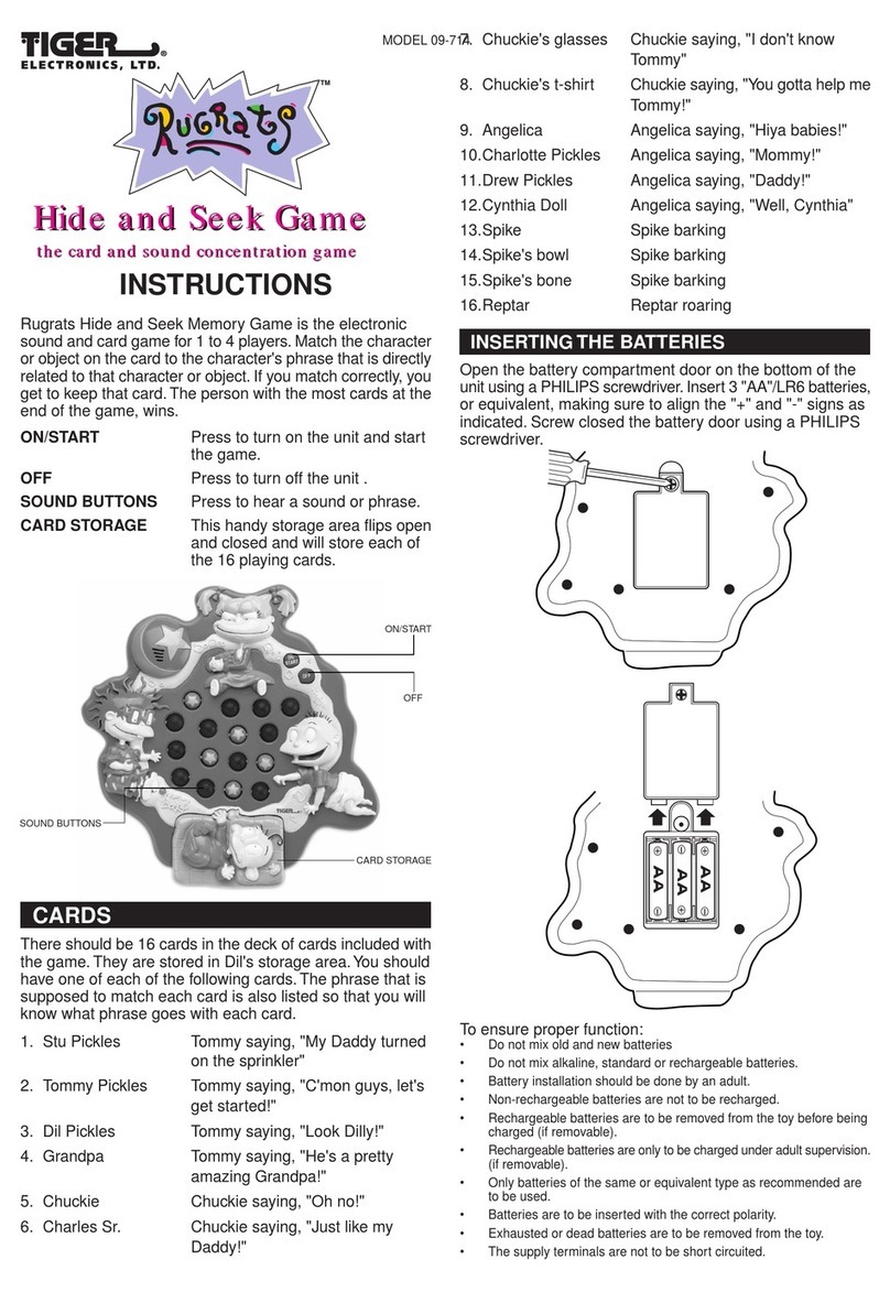
Tiger Electronics
Tiger Electronics Rugrats Hide and Seek Game 09-714 instructions

Minicraft Models
Minicraft Models USAF C-130H Assembly instructions
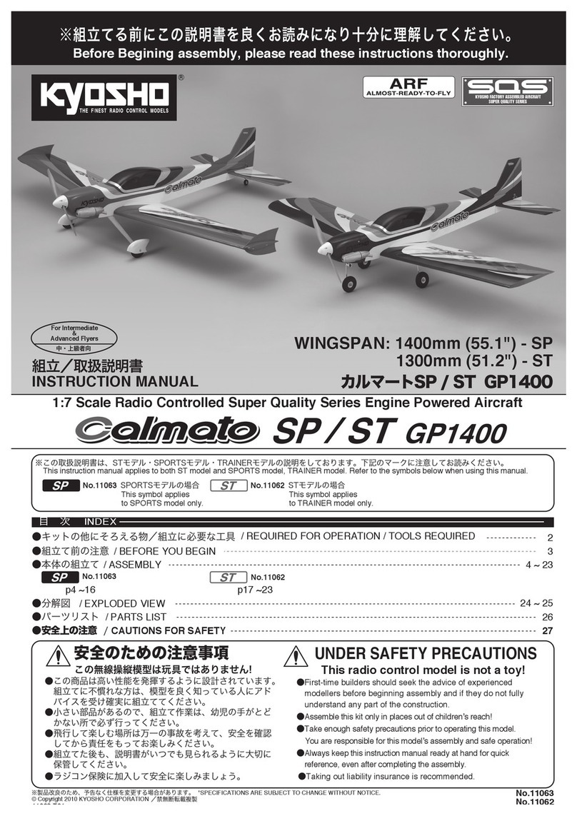
Kyosho
Kyosho SQS Calmato SP GP1400 instruction manual

Eduard
Eduard Phantom FGR Mk.2 Assembly instructions

Fisher-Price
Fisher-Price 73769 instructions
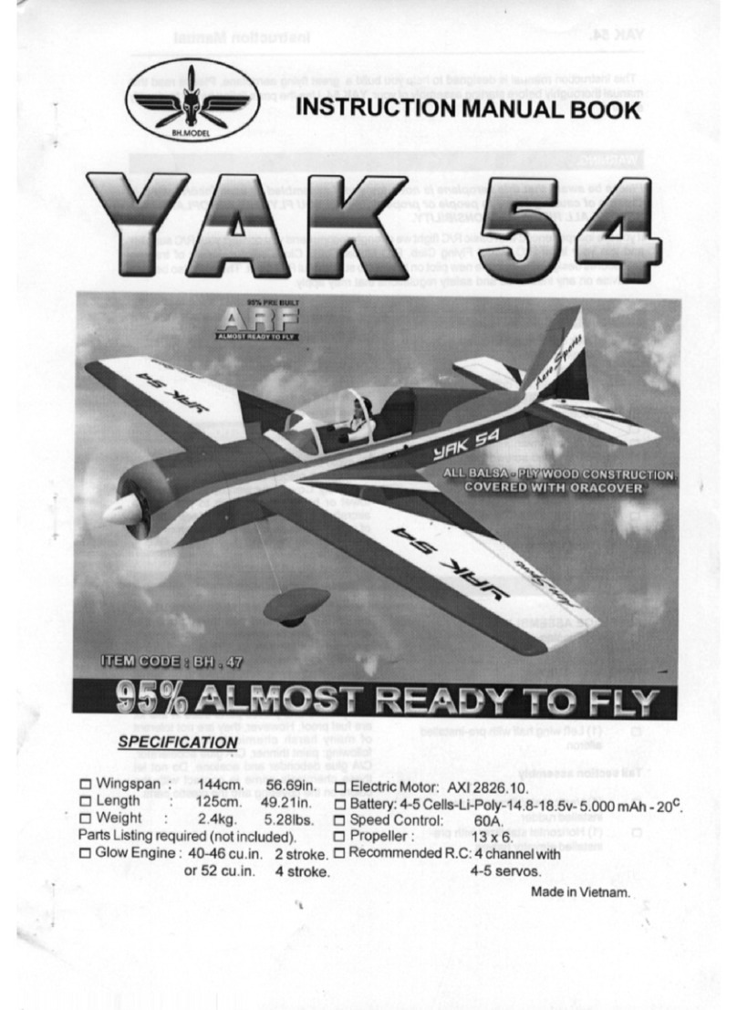
BH Model
BH Model YAK 54 BH.47 Instruction manual book

