TABLE
OF
CONTENTS
.... ....
" u
"'
0
"' "'
"'
"'
"'
N
:!.
...
"'
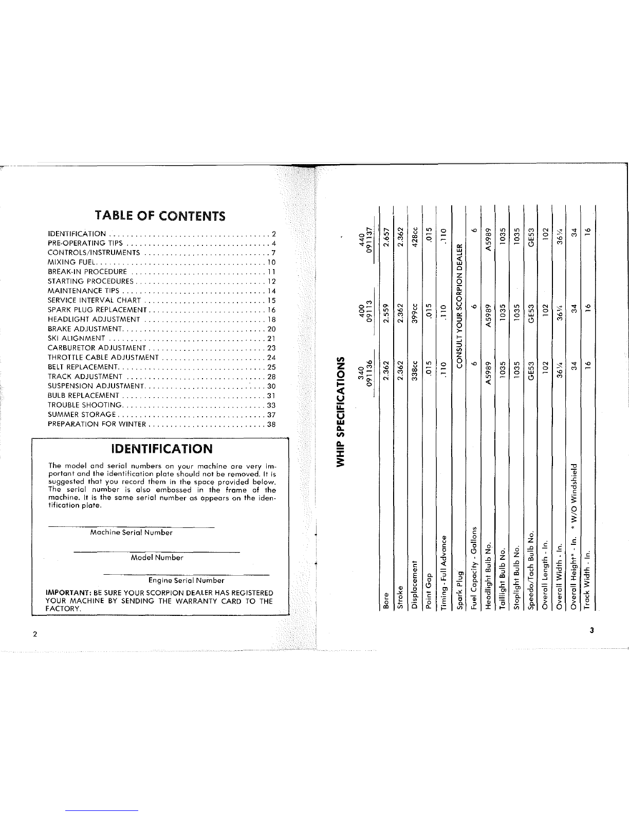
IDENTIFICATION
.....................................
2 o"'
"'
"'
u
co
(')
(')
"'
0
"'
... -
"'
(')
co
"'
"'
0 0
UJ
"'
PRE·OPERATING
TIPS
.................................
4 ... -" " N -:
"'
0
(')
"'
...
"'
<(
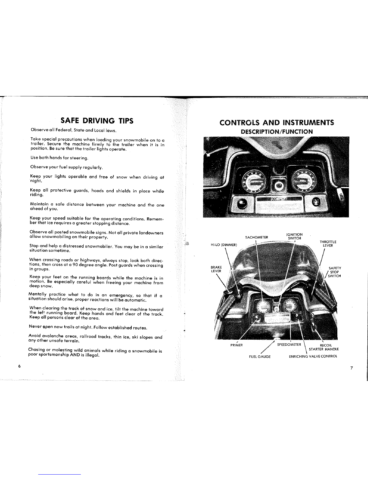
CONTROLS/INSTRUMENTS
.............................
? 0
UJ
~
MIXING
FUEL
.......................................
10
<(
UJ
BREAK·IN PROCEDURE
...................
"
...........
11
Cl
z
STARTING PROCEDURES.
..
"
..
"
.......................
12 Q
MAINTENANCE
TIPS
...
.
".
"
.......................
14
"-
"'
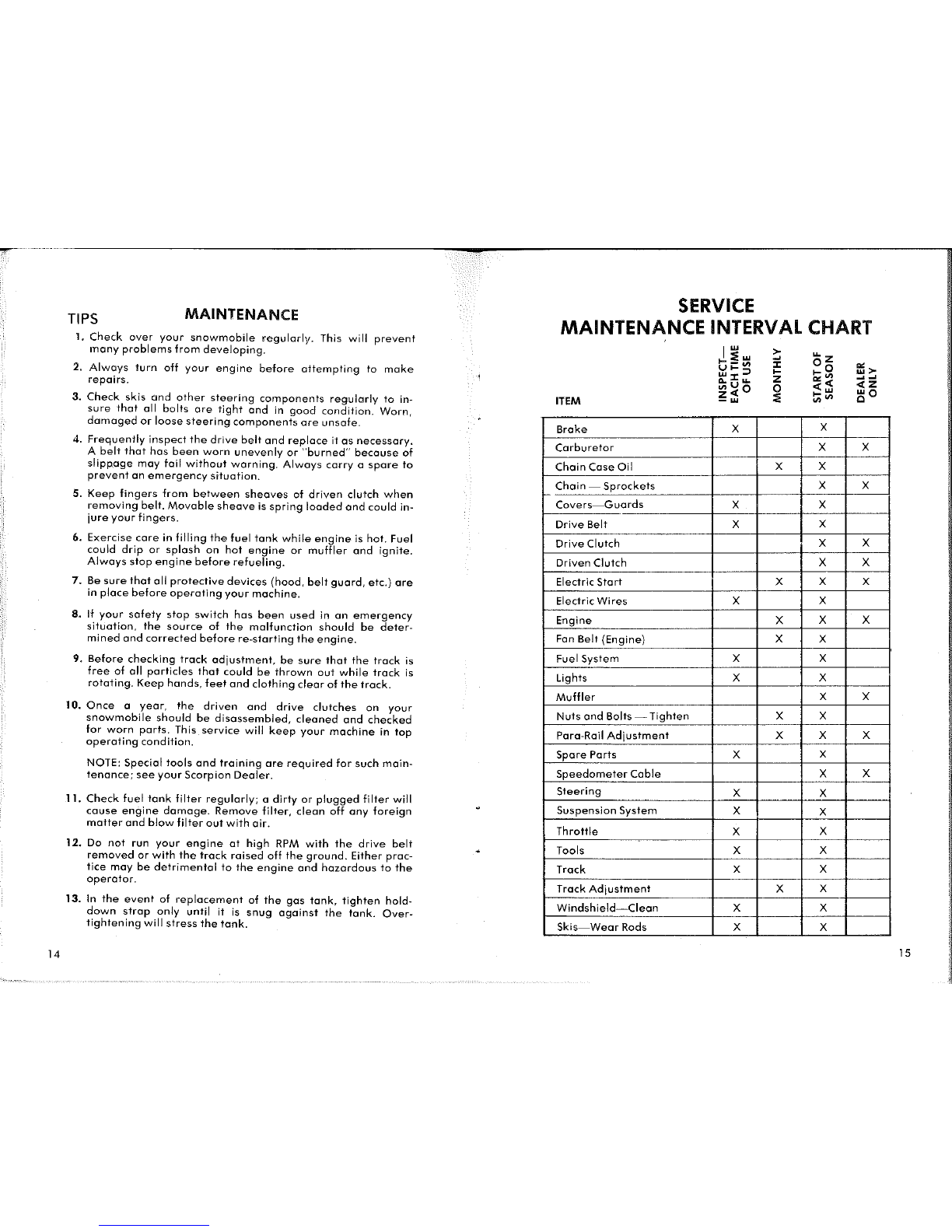
SERVICE
INTERVAL CHART 15
(')
0
........
'
.......
u
o-
"'
" u
"'
0
"'
"' "' "'
(')
"
:!.
...
"'
SPARK PLUG REPLACEMENT
.............
"".""
.........
16
o-
"'
"'
u <J)
co
(')
(')
"'
0
(')
""'
"'
(')
"'
"'
"' "'
0 0
UJ
"'
HEADLIGHT ADJUSTMENT
....
"
.......................
18 " "
"'
-:
::J
"'
0
(')
0
(')
BRAKE ADJUSTMENT.
................................
20 0 <(
>-
SKI
ALIGNMENT
....................
21
t-
. . . . . . . . . -. . . . . .
~
CARBURETOR ADJUSTMENT
...........................
23 ::J
<J)
THROTTLE CABLE ADJUSTMENT
........................
24
z
"'
"'
0
z " " u
"'
0
"'
"'
"'
"'
(')
"
:!.
...
"'
BELT
REPLACEMENT
........
. "
..................
25
o"'
"'
"'
u u
co
(') (')
"'
0
(')
co
0 ... -
(')
(')
(')
"'
-:
"'
0 0
UJ
"'
TRACK ADJUSTMENT "
.....
"
.........................
28
(')-
"
"'
0
(')
i=
"'
"
(')
<(
SUSPENSION ADJUSTMENT
........................
·
....
30
0
c(
BULB REPLACEMENT
.................................
31
~
TROUBLE
SHOOTING
.................................
33
II.
SUMMER STORAGE
..................................
37
0
PREPARATION
FOR
WINTER
...........................
38 w
a..
"'
IDENTIFICATION
a..
J:
The
model
and
serial
numbers
on your
machine
are
very
im- ;: "'0
portant
and
the
identification
plate
should
not
be
removed.
It
is
a;
.<:
suggested
that
you
record
them
in
the
space
provided
below.
"'
The
serial
number
is
also
embossed
in
the
frame
of
the
"'0
c
machine.
It
is
the
same
serial
number
as
appears
on
the
iden-
3:
tification
plate.
0
"
3:
"'
•
Machine
Serial
Number
c 0
"
.2
z £
u 0
c 0 0
"'
c c
0 0 z 0 "
> z
~
•
Model
Number
"'0
..c
z
"'
.<:
~
i
~
<(
>-
..c ..c
~
.<: ..c
c
~
~ .<:
Ol
"C
.S!'
"
·u
"'
~ u c .<:
E
~
Ol
~
"'
a "
3:
"
~
a.
u..
~ 0
1:
"'
t-
~
:c
"'0
Engine Serial
Number
" 0 a.
1:
1:
"
3:
u 0
"-
0
.S!'
0 =
"
.2
Ol
u
Ol Ol
"'0 0 0 0
IMPORTANT:
BE
SURE
YOUR SCORPION
DEALER
HAS
REGISTERED
-"
1:
c -" "'0
~ ~ ~
-"'
" 0 a.
~
a; 0 a. " " " " u
YOUR
MACHINE
BY
SENDING
THE
WARRANTY CARD TO
THE
~
~
"'
E 0 0 " > > > 0
0
~
0 0 a. ~ " 0
~
a.
~
FACTORY.
"'
<J)
"-
;.=
<J)
u..
:c
t-
<J) <J) 0 0 0
t-
2 3