SDI DA-500 User manual
DA-500
100-600 MHz DISTRIBUTION AMPLIFIER
OPERATING MANUAL
SPECTRADYNAMICS, INC • 1849 Cherry St. Unit 2. • Louisville, CO 80027
Phone: (303) 665-1852 • Fax: (303) 604-6088
www.spectradynamics.com
SPECTRADYNAMICS, INC

DA-500, 100-600 MHz Distribution Amplifier Operating Manual
Copyright © 2020 SpectraDynamics, Inc. All rights reserved.
DA-500:R0-2020-FA

Contents
1.0 Introduction …………………………………………………………………….... 1
2.0 Safety and preparation for use ………………………………..……….…….. 2
2.1 Electrical ……………….…………………………………………….……. 2
2.2 Instrument ……..…………….………………………………….….…….. 3
3.0 Front panel description …….…………………………………………….…… 4
4.0 Back panel description ………………………………………………….……. 5
5.0 Installation ……………………………………………………………….…….. 6
6.0 Operation ……………………………………………………………………… 7
7.0 Troubleshooting ………………………………………………………………. 8
8.0 Specifications …………………………………………………………………. 9
9.0 Warranty and service ………………………………………………………… 10


1.0 Introduction
Page 1
The DA-500 is a general purpose isolation amplifier designed to distribute frequencies
from 100 to 600 MHz. This Amplifier offers 80 dB of channel-to-channel isolation and 85
dB of reverse isolation at 500 MHz. The low phase-noise, (-130 dBc/Hz at 1 Hz and -160
dBc/Hz at 10 KHz) ensures that the distributed signals are not degraded. The outputs
have a low VSWR, typically 1.2 (return loss of 20 dB), to minimize environmental effects
on frequency distribution through long transmission lines. There are two inputs (SIGNAL A
and B) each driving six outputs.The instrument is equipped with power level monitors that
compare output power levels to a preset threshold of +7dBm. If the signal on any output
drops below this threshold, the monitor LED located on the front panel and corresponding
to either SIGNAL A or B, will turn off indicating a fault condition. The inputs and outputs
are chassis grounded. The standard unit has two inputs and twelve outputs. The DA-500
operates on 100 to 240 VAC, and is offered in a stand-alone rack-mount enclosure with
dimensions of 1U X 19” X 14”.

2.0 Safety and Preparation for Use
Page 2
The DA-500 was designed for indoor use only and is not intended for operation outdoors
or in a wet environment. The instrument may be mounted in a standard 19-inch
instrumentation rack or may be used on a laboratory bench.
Inspect the instrument and power cords for damage before first use.
2.1 Electrical safety and preparation for use
Voltages capable of causing injury or death are present in this instrument. Use extreme
caution whenever the instrument cover is removed.
Line Voltage
This instrument is designed to operate with a 100 to 240 VAC, 47 to 63 Hz power source.
Optional DC operation with +12 to +36 VDC, 2 Amperes is also possible.
Fuse
A 1.0 Ampere 250V 5X10mm slow-blow fuse is used for 100-240 VAC operation.
A 2.0 Ampere 250V 5X10mm slow-blow fuse is used for the DC power protection.
Only replace fuse with the same type and specifications.
AC Power
The instrument has a detachable three wire power cord for connection to a grounded AC
power source. The enclosure of the unit is directly connected to the outlet ground to
protect against electrical shock. Always use an outlet with a protective ground and do not
disable this safety mechanism. Detaching the AC power cord is the only option of
disconnecting the unit from the AC mains supply. Make sure you have access to the rear
panel or provide an external accessible AC disconnect means for the DA-500.
DC Power
When ordered with the DC power option, the requirements for the external DC power
supply are +12 to +36 VDC at 2 Amperes. The following specifications should be used to
ensure the optimum performance of the DA-500:
DC Supply voltage +12 to +36 VDC, 2 Amps
Line regulation +/- 0.05% for a 10% line change
Load regulation +/- 0.05% for a 50% load change
Output ripple < 5 mV peak-to-peak

2.0 Safety and Preparation for Use
Page 3
The instrument ordered with the DC power option has a RM12BRD-6PH(71) DC connector
on the back panel with the following configuration:
Pin 1 NC
Pin 2 NC
Pin 3 NC
Pin 4 +12 to +36 VDC power return
Pin 5 +12 to +36 VDC power
Pin 6 Chassis GND /Earth GND
Verify that the connector from the DC power supply to be used has the pin configuration
mentioned above. Do not apply AC voltage to the DC power connector. Failure to follow
these directions may cause injury or death to personnel, cause irreparable damage to the
instrument and voids all warranties.
Please note that the power return (pin 4) is NOT connected to the instrument case ground
internally, however both ground connections pin 4) and pin 6) are available at the DC
power connector and may be connected together at this point.
2.2 Instrument safety and preparation for use
The DA-500 is designed to distribute RF signals with a frequency of 100 to 600 MHz .
Output levels below +7dBm will trigger a fault condition which can be monitored from the
front panel. Input signals must be kept below +20 dBm as greater power levels will damage
the unit and void all warranties.
Absolute Maximum Ratings
Input RF Power +20dBm Maximum
Reverse RF Power +20dBm Maximum
Voltage at the RF Input 0 V Maximum
Voltage at the RF Output 50 V Maximum

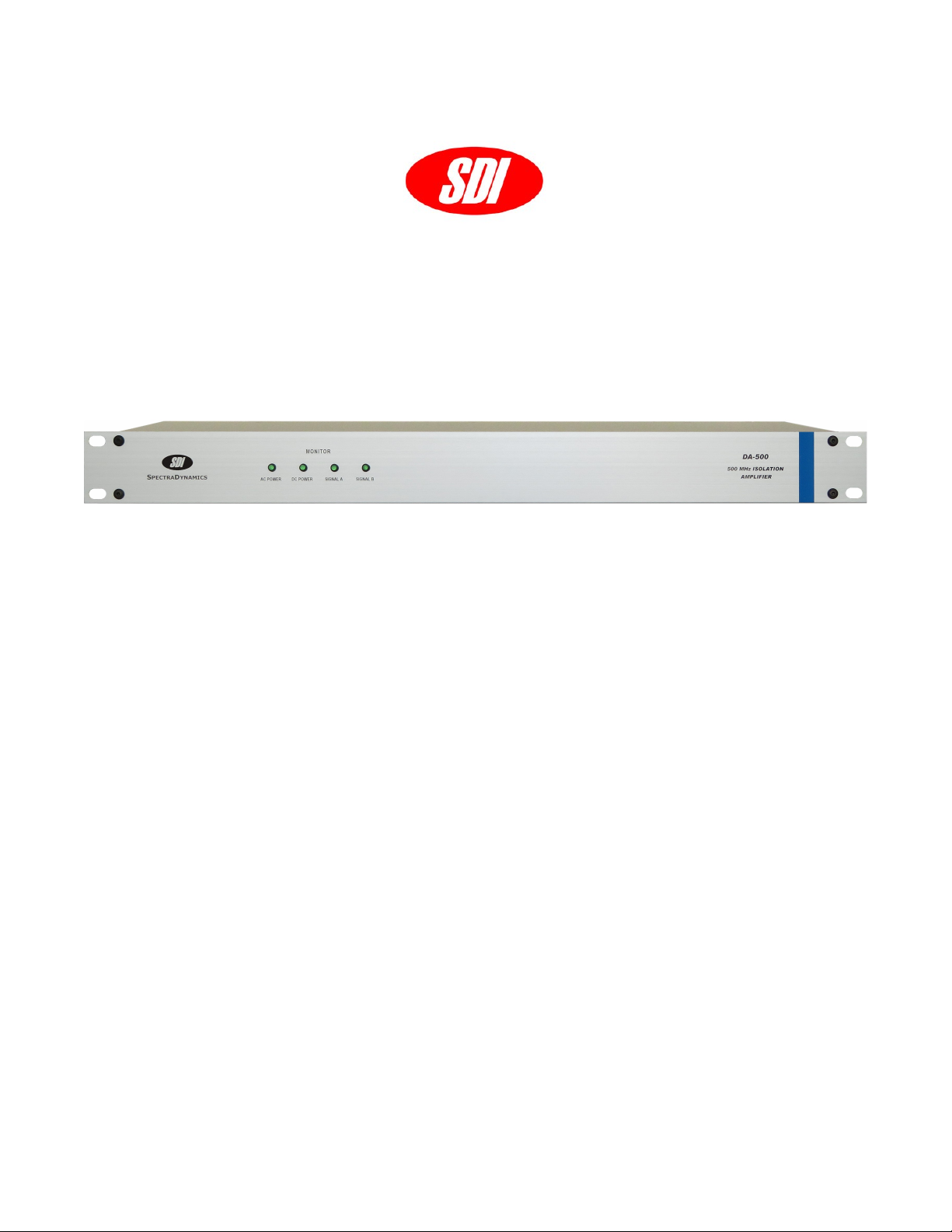
3.0 Front Panel
Page 4
AC Power
The AC Power LED turns on when AC power is applied to unit.
DC Power
The DC Power LED is on when DC power is applied to unit.
SIGNAL A
The SIGNAL A LED will be on if all RF outputs A-1 through A-6 are greater than +7 dBm.
SIGNAL B
The SIGNAL B LED will be on if all RF outputs B-1 through B-6 are greater than +7 dBm.
RF signal levels less than +7 dBm will trigger a fault condition and the SIGNAL LED will
not turn on. However, the DA-500 will still provide six buffered copies of every RF input
signal.
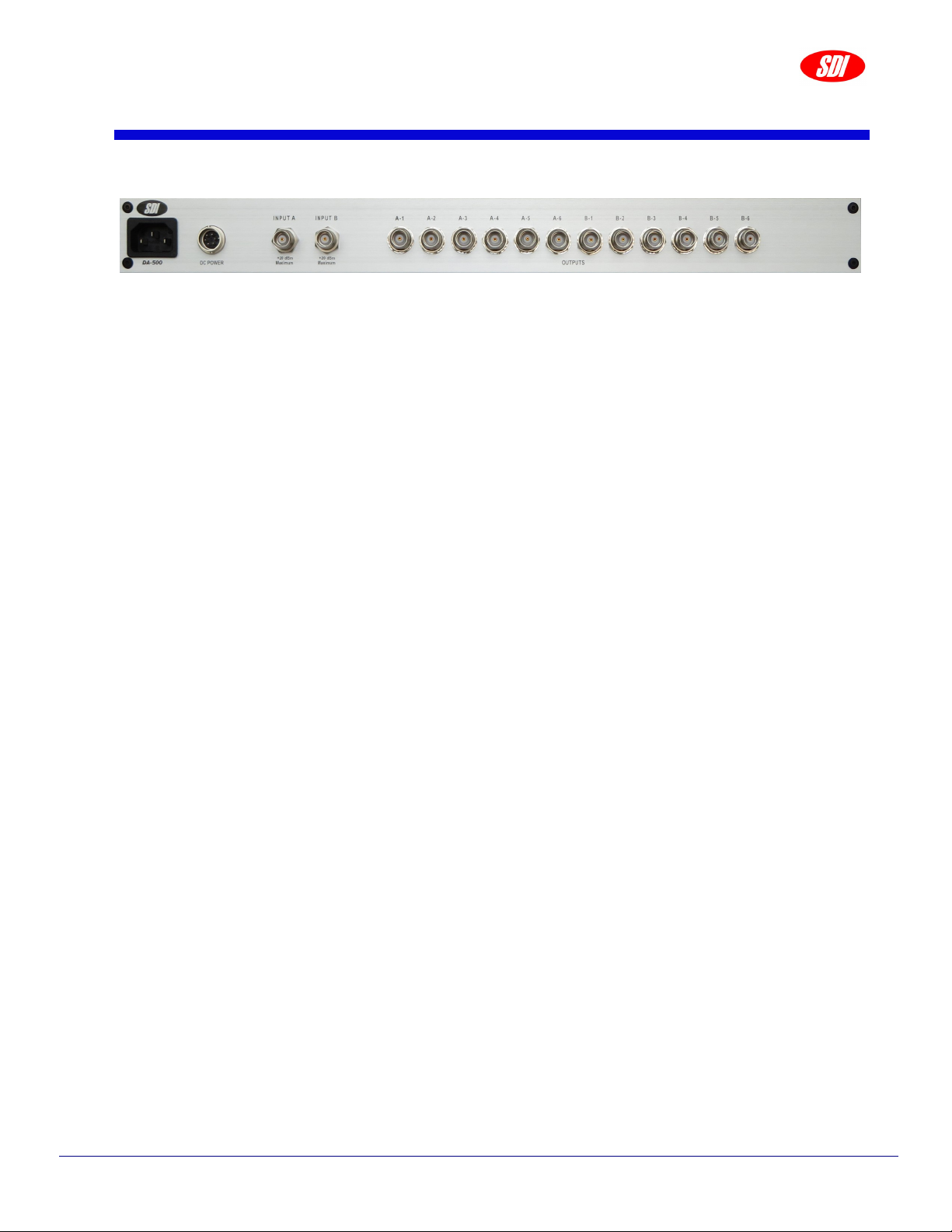
4.0 Back Panel
Page 5
AC Power
The DA-500 is configured to operate on 100 to 240 VAC.
DC Power
If the DC power option is installed, this instrument may also operate on DC power from +12
to +36 VDC as the main power supply. When the DA-500 is set up to operate with both AC
and DC power sources at the same time the DC power is used as backup power in case of
AC power outages.
INPUT A
A RF Signal within the range of 100 MHz to 600 MHz may be connected to the TNC
connector labeled INPUT A.
INPUT B
A RF Signal within the range of 100 MHz to 600 MHz may be connected to the TNC
connector labeled INPUT B.
OUTPUTS A-1 through A-6
Six buffered copies of the RF input signal A will be available at the TNC connectors labeled
A-1 through A-6. Any DA-500 output may be used to drive the input of another distribution
amplifier.
OUTPUTS B-1 through B-6
Six buffered copies of the RF input signal B will be available at the TNC connectors labeled
B-1 through B-6. Any DA-500 output may be used to drive the input of another distribution
amplifier.

5.0 Installation
Page 6
5.1 Connecting power
The DA-500 ships with a standard North American or European IEC power cord and with a
RM12BPE-6S(81) DC connector for units ordered with the DC power option. The
instrument may be mounted in a standard 19-inch instrument rack or may be operated on
a laboratory bench.
Locate the AC POWER entry module on the rear of the enclosure and connect the power
cord.
If the unit was acquired with the DC POWER option you may use the DC connector
shipped with the unit to assemble a DC power cable. The DC connector pin configuration
is shown on page 3. Proceed to connect the DC cable to the DC Connector located on the
rear of the enclosure.

6.0 Operation
Page 7
Plug the AC power cord into an appropriate AC power outlet. You may also plug the DC
power cable to an appropriate DC power supply.
Once AC power is supplied to the DA-500, the LED on the front panel labeled AC POWER
will turn on. If you also applied DC voltage, the LED labeled DC POWER will also turn on.
The DA-500 is designed to distribute signals from 100MHz to 600 MHz. The RF input has
a 50-ohm input impedance. Provide a signal within the mentioned frequency range to the
TNC connector on the back panel labeled INPUT. If the RF signal has a power level
greater than +7dBm, the monitor LED located on the front panel will light up.
Six buffered copies for each RF input signal is available on the TNC connectors located on
the back panel labeled OUTPUTS.

7.0 Troubleshooting
Page 8
Do not attempt to service or adjust the instrument unless another person, capable of
providing first aid or resuscitation, is present. If there are problems that cannot be
resolved by the troubleshooting steps below please contact technical support.
Technical Support
Tel: +1 (303) 665-1852 , Fax: +1 (303) 604-6088
support@spectradynamics.com, www.spectradynamics.com
AC Power LED does not turn on.
Disconnect AC and DC power cords. Remove the top cover. Check the AC power fuse and
power cord. If the fuse is blown replace with same type and rating.
DC Power LED does not turn on.
Disconnect AC and DC power cords. Remove the top cover. Check the DC power fuse
and power cord. If the fuse is blown replace with same type and rating.
Please contact SpectraDynamics if any of the fuses blows again or if the event that caused
the fuse to blow is not known.
Monitor LED is off.
Check to see if the RF signal provided to the instrument is greater than +7 dBm.
Check to see if a signal is present at all outputs of the signal distribution module.
The Monitor LED will remain off with a power lever under +7dBm, but will still provide six
copies of the RF input signal. If the instrument is providing the copies of the input signal
you may continue using the DA-500.
If the power level of the RF signal provided is greater than +7dBm and the Monitor LED
remains off, the instrument will have to be returned for repair.

8.0 Specifications
Page 9
*All tests done at 100 MHz and +10 dBm output unless otherwise specified.
Rackmount chassis 1U H, 19“ W, 14” D
Power consumption 25 Watts
Weight 11 lbs
Storage temperature -10 to +75 ºC
Operation environment 0 to +50 ºC
Humidity 5% to 95% Non-condensing
PARAMETER CONDITIONS MIN TYP MAX UNITS
Input power level 1 dB compression 13 - dBm
Bandwidth +/- 1 dB 100 600 - MHz
Gain @ 500 MHz 0 1 2 dB
Impedance Input
Output
-
-
50
50
-
-
Ohms
Return loss
Input (S11)
Output (S22)
-
-
-21
-21
-20
-20
dB
Distortion +10 dBm - -40 -35 dBc
Isolation Output to output
Output to input
75
80
80
85
-
-
dB
Phase noise
(+13dBm )
1 Hz
10 Hz
1 kHz
10 kHz
-
-
-
-
-133
-145
-159
-161
-130
-140
-155
-160
dBc/Hz

9.0 Warranty and Service
Page 10
The DA-500 is warranted to be free of defects under normal operating conditions, as
specified, for one year from date of original shipment from SpectraDynamics, Inc. (SDI).
SDI’s obligation and liability under this warranty is expressly limited to repairing or
replacing, at SDI’s option, any product not meeting the said specifications. This warranty
shall be in effect for one (1) year from the date a DA-500 is sold by SDI. SDI makes no
other warranty, express or implied, and makes no warranty of the fitness for any particular
purpose. SDI’s obligation under this warranty shall not include any transportation charges
or costs of installation or any liability for direct, indirect, or consequential damages or
delay. Any improper use, operation beyond capacity, substitution of parts not approved by
SDI, or any alteration or repair by others in such manner as in SDI’s reasonable judgement
affects the product materially and adversely shall void this warranty. No employee or
representative of SDI is authorized to change this warranty in any way or grant any other
warranty.
Service
Do not attempt to service or adjust the instrument unless another person, capable of
providing first aid or resuscitation, is present. Please remember that any alteration or repair
may void the warranty. Contact SDI with any questions or to request an RMA if a repair is
needed.
SpectraDynamics, Inc.
1849 Cherry Street Unit 2.
Louisville, CO 80027
USA
Tel: (303) 665-1852
Fax: (303) 604-6088
support@spectradynamics.com
www.spectradynamics.com

Table of contents
Other SDI Amplifier manuals


Popular Amplifier manuals by other brands


AUSTRALIAN MONITOR
AUSTRALIAN MONITOR AMIS1202P operating manual

Marshall Amplification
Marshall Amplification ORIGIN 20 user manual

NTI
NTI MegaDipol MD300DX operating manual

Lab.gruppen
Lab.gruppen C 28:4 Technical data

WLM Acoustic
WLM Acoustic Sonata owner's manual

Crown
Crown POWER BASE 1 Reference manual