SeaCom 3000 User manual

SeaCom3000 User Manual Page 2 of 94
SeaCom TMN20170417CJ01_0109
SeaCom 3000
User Manual
This manual co ers the SeaCom 3000 telephone, talk-back command and intercom
system. It includes all the telephone and intercom stations SC211, SC220, SC411
and SC421.
SeaCom3000 User Manual Page 3 of 94
SeaCom TMN20170417CJ01_0109
SeaCom3000 User Manual Page 4 of 94
SeaCom TMN20170417CJ01_0109
SeaCom3000 User Manual Page 5 of 94
SeaCom TMN20170417CJ01_0109

SeaCom3000 User Manual Page 6 of 94
SeaCom TMN20170417CJ01_0109

SeaCom3000 User Manual Page 7 of 94
SeaCom TMN20170417CJ01_0109
CONTENT
1. INTRODUCTION................................................... 12
1.1 PURPOSE OF THIS MANUAL ................... 12
1.2 LIABILITY ........................................... 12
1.3 REVISIONS ......................................... 12
1.4 IMPORTANT SAFETY NOTES.......... 13
2. SYSTEM OVERVIEW ........................................... 14
2.1 OPERATIONAL FEATURES ..................... 14
2.1.1 ON BOARD COMMUNICATION ............... 14
2.1.2 DISTRIBUTE SATELLITE COMMUNICATION
14
2.1.3 TALK BACK COMMAND CALLS............... 14
2.1.4 PA FUNCTIONS ................................. 14
2.1.5 TIME DISTRIBUTION AND WAKE UP ........ 14
2.2 MAIN SYSTEM COMPONENTS................. 14
2.2.1 SEACOM 3000 ................................. 14
2.2.2 SC211 ........................................... 15
2.2.3 SC411 ........................................... 15
2.2.4 SC421 ........................................... 15
2.2.5 SC220 ........................................... 16
2.2.6 TELEPHONES ................................... 16
2.3 TYPICAL INSTALLATION EXAMPLE........... 17
2.4 ............................................................ 17
3. DESIGNING A SYSTEM....................................... 18
3.1 ANALYZING ........................................ 18
3.1.1 COUNTING LOCATIONS ....................... 18
3.1.2 ENVIRONMENT ................................. 18
3.1.3 TYPE OF COMMUNICATION .................. 18
3.1.4 SATELLITE LINES............................... 18
3.2 SELECTING TELEPHONES/STATIONS ....... 18
3.2.1 ANALOGUE TELEPHONES.................... 18
3.2.2 SC411 ........................................... 18
3.2.3 SC211 ........................................... 19
3.2.4 SC421 ........................................... 19
3.2.5 SC220 ........................................... 19
3.2.6 FEATURES OVERVIEW ........................ 19
3.3 DESIGNING THE EXCHANGE SYSTEM ....... 1
3.3.1 AEXT16 ......................................... 19
3.3.2 FIO4 .............................................. 19
3.3.3 CTU2 AND CTU24 ........................... 19
3.3.4 PDU............................................... 20
3.3.5 EXCHANGE DESIGN EXAMPLE .............. 20
3.4 POWER CONSIDERATIONS ..................... 20
3.4.1 POWER CONSUMPTION - EXCHANGE ..... 20
3.4.2 POWER CONSUMPTION - STATIONS ...... 20
3.5 WIRING SCHEMATIC ............................. 20
4. INSTALLATION .................................................... 21
4.1 THE EXCHANGE................................... 21
4.2 MOUNTING THE STATIONS..................... 21
4.2.1 FLUSH MOUNT.................................. 21
4.2.2 BULKHEAD MOUNT ............................ 22
4.3 FUSES ............................................... 22
4.3.1 COMMON POWER SUPPLY ONLY .......... 22
4.4 CABLES............................................. 22
4.5 SHIELDING AND PROTECTIVE EARTH ....... 23
4.6 GOOD PRACTICE SHIELDING .................. 23
4.6.1 AT THE EXCHANGE............................ 23
4.6.2 AT THE STATIONS ............................. 23
5. OPERATION ......................................................... 24
5.1 MAKING AND TRANSFERRING A CALL ...... 24
5.2 RINGING SIGNALS................................ 24
5.3 TONE SIGNALS.................................... 24
5.4 PRIORITY CALL ................................... 24
5.5 DIRECT IN .......................................... 24
5.6 DIRECT IN TO RINGING GROUP ............... 24
5.7 SETTING SYSTEM TIME ......................... 25
5.8 ORDERING A WAKE-UP CALL ................ 25
5. RINGING GROUPS ................................ 25
5.10 PAGING CALLS.................................. 25
5.11 PA GROUP CONFERENCE ................... 25
5.12 ALARM CALLS .................................. 25
5.13 CALL PICKUP.................................... 25
5.14 MUSIC WHEN FREE ............................ 25
5.15 TALK-BACK COMMAND CALLS ............. 26
5.16 CONFERENCE ................................... 26
5.17 DO NOT DISTURB............................... 26
5.18 DAY-MODE NIGHT-MODE..................... 26
5.1 CALLS VIA TRUNK LINES ..................... 26
6. SEACOM3000 ....................................................... 27
6.1 SEACOM 3000 ................................... 27
6.2 CABLE ENTRIES .................................. 27
6.3 THE SYSTEM INSIDE ............................. 27
6.4 MECHANICAL DIMENSIONS .................... 28
6.5 CIRCUIT BOARDS................................. 2
6.5.1 THE AEXT16 .................................. 29
6.5.1.1 Board layout ................................ 29
6.5.1.2 Jumpers ...................................... 29
6.5.1.3 Indicators .................................... 30
6.5.2 THE FIO4 ....................................... 30
6.5.2.1 Jumpers ...................................... 30
6.5.2.2 Board layout ................................ 30

SeaCom3000 User Manual Page 8 of 94
SeaCom TMN20170417CJ01_0109
6.5.2.3 FIO4 Connectors ......................... 31
6.5.2.4 Trunk lines................................... 31
6.5.2.5 Audio I/O ..................................... 31
6.5.2.6 Relays......................................... 31
6.5.2.7 Digital input ................................. 31
6.5.2.8 Zone relay dri e ........................... 31
6.5.2.9 Indicators .................................... 31
6.5.3 PIM................................................ 32
6.5.3.1 Board layout ................................ 32
6.5.3.2 Power connector .......................... 32
6.5.3.3 Fuses .......................................... 32
6.5.3.4 Indicators .................................... 32
6.5.4 CTU24 ........................................... 33
6.5.4.1 Board layout ................................ 33
6.5.5 LSP ............................................... 33
6.5.5.1 Board layout ................................ 33
6.5.6 BACKPLANE ..................................... 34
6.5.6.1 Board layout ................................ 34
7. COMMUNICATION STATIONS ........................... 35
7.1 MECHANICS AND MOUNTING .................. 35
7.1.1 THE KEYBOARD ................................ 35
7.1.2 INS AND OUTS .................................. 35
7.1.3 GORE VENT ..................................... 35
7.1.4 MOUNTING BRACKETS ....................... 36
7.1.5 CABLES AND SHIELDING ..................... 36
7.1.6 THE SILICA GEL BAG .......................... 36
7.1.7 THE HANDSET .................................. 37
7.1.7.1 Mounting the handset ................... 37
7.1.8 HEADSET......................................... 38
7.1.8.1 Mounting headset connector ......... 38
7.1.9 EXPOSED EQUIPMENT........................ 38
7.1.9.1 Mounting the door ........................ 39
7.1.10 FEATURES OVERVIEW ...................... 40
7.1.11 HANDSET MECHANICAL OUTLINE ........ 41
7.1.12 CROSS RAIL DRAWING ..................... 41
7.2 SC211 .............................................. 42
7.2.1 DESCRIPTION ................................... 42
7.2.2 SPECIFICATION................................. 42
7.2.3 INSIDE............................................. 42
7.2.4 ELECTRICAL CONNECTIONS ................ 43
7.2.5 JUMPER FIELD .................................. 43
7.2.6 VOLUME SETTINGS ............................ 43
7.2.7 OPERATING ..................................... 44
7.2.7.1 Making calls................................. 44
7.2.7.2 Recei ing calls............................. 44
7.2.7.3 Conducting calls .......................... 44
7.2.7.4 Terminating a call......................... 44
7.2.7.5 Recei ing paging calls.................. 44
7.2.7.6 Command group (talk-back).......... 44
7.2.8 MECHANICAL OUTLINE ....................... 45
7.2.9 PCB LAYOUT ................................... 46
7.2.10 SCHEMATIC ................................... 47
7.3 SC220 .............................................. 48
7.3.1 DESCRIPTION ................................... 48
7.3.2 SPECIFICATION................................. 48
7.3.3 ON THE FRONT ................................. 48
7.3.4 INSIDE............................................. 49
7.3.5 ELECTRICAL CONNECTIONS ................ 49
7.3.6 PROGRAMMING ................................ 49
7.3.7 OPERATING ..................................... 50
7.3.7.1 Handset calls............................... 50
7.3.7.2 Headset calls............................... 50
7.3.7.3 PTT mode ................................... 50
7.3.7.4 Recei ing calls ............................ 50
7.3.7.5 Timed termination ........................ 50
7.3.7.6 Busy tone termination .................. 50
7.3.7.7 Call transfer................................. 50
7.3.8 MECHANICAL OUTLINE ....................... 51
7.3.9 PCB LAYOUT ................................... 52
7.3.10 SCHEMATIC ................................... 53
7.4 SC411 / SC421 ................................. 54
7.4.1 DESCRIPTION................................... 54
7.4.2 SPECIFICATIONS............................... 54
7.4.3 ON THE FRONT ................................. 55
7.4.4 INSIDE ............................................ 55
7.4.5 ELECTRICAL CONNECTIONS ................ 55
7.4.6 J2 - RS422 INTERFACE ..................... 55
7.4.7 KEYS .............................................. 56
7.4.7.1 F1 to F3 ...................................... 56
7.4.7.2 Up down keys.............................. 56
7.4.7.3 M key.......................................... 56
7.4.7.4 Speaker key (hands f ree) ............. 56
7.4.7.5 PTT key ...................................... 56
7.4.7.6 R key (transfer)............................ 56
7.4.8 DISPLAY.......................................... 56
7.4.8.1 Status field .................................. 56
7.4.9 CALL INDICATOR ............................... 56
7.4.10 BACKLIGHT CONTROL ...................... 56
7.4.11 MOUNTING THE SC411 ................... 56
7.4.12 OPERATING ................................... 58
7.4.12.1 Modes of con ersation ............... 58
7.4.12.2 Dialing ...................................... 58
7.4.12.2.1 Speed dial .............................. 58
7.4.12.2.2 Memory dial ........................... 58
7.4.12.2.3 Last number re-dial ................. 58
7.4.12.2.4 Call lists and re-dial ................. 58
7.4.12.3 How to answer a call .................. 58
7.4.12.4 Direct in calls ............................. 58
7.4.12.5 Voice acti ated answering .......... 58
7.4.12.6 Terminating a call ...................... 58
7.4.12.7 Switching mode of con ersation.. 58
7.4.12.8 Switching between PTT and full duplex
58
7.4.12.9 PA call and PA olume............... 59
7.4.13 THE MENU SYSTEM ......................... 60
7.4.13.1 Na igating in the menu............... 60
7.4.13.2 The menu – o er iew................. 60
7.4.13.2.1 Speaker olume ...................... 60
7.4.13.2.2 Backlight ................................ 60
7.4.13.2.3 Ringer olume ........................ 60
7.4.13.2.4 P.A. olume ............................ 60
7.4.13.2.5 Bell signal............................... 60
7.4.13.2.6 Calls out ................................. 60
7.4.13.2.7 Call in..................................... 60
7.4.13.2.8 Auto answer ........................... 60
7.4.13.2.9 Auto busy ............................... 60
7.4.13.2.10 Direct in ................................ 60

SeaCom3000 User Manual Page 9 of 94
SeaCom TMN20170417CJ01_0109
7.4.13.2.11 Hands free ............................ 61
7.4.13.2.12 External speaker ................... 61
7.4.13.2.13 Date & time ........................... 61
7.4.13.2.14 Speed dial............................. 61
7.4.13.2.15 Memory dial .......................... 61
7.4.13.2.16 Dial signal ............................. 61
7.4.13.2.17 Loop dial type........................ 61
7.4.13.2.18 Remote PTT ......................... 61
7.4.13.2.19 Remote Hook Switch ............. 61
7.4.13.2.20 Local Extern Microphone ....... 61
7.4.13.2.21 Headset microphone type ...... 61
7.4.13.2.22 Headset VOX ........................ 61
7.4.13.2.23 Local microphone gain ........... 62
7.4.13.2.24 Handset microphone gain ...... 62
7.4.13.2.25 Headset microphone gain ...... 62
7.4.13.2.26 External microphone gain....... 62
7.4.13.2.27 Relay mode........................... 62
7.4.13.2.28 Relay hold off ........................ 62
7.4.13.2.29 Contrast ................................ 62
7.4.13.2.30 F1 mode ............................... 62
7.4.13.2.31 Voice hook off ....................... 62
7.4.14 MECHANICAL OUTLINE ..................... 63
7.4.15 PCB LAYOUT ................................. 64
7.4.16 SCHEMATIC ................................... 65
8. SYSTEM PROGRAMMIN G .................................. 68
8.1 GETTING ACCESS TO THE CONFIGURATION
68
8.1.1 SHARED FOLDER ACCESS ................... 68
8.1.2 USB ACCESS ................................... 69
8.1.3 REMOTE DESKTOP ACCESS................. 69
8.2 GENERAL CONCEPTS ........................... 71
8.2.1 CALL NUMBERS / DESCRIPTIONS .......... 71
8.2.2 SERVICE GROUPS ............................. 71
8.2.3 THE SERVICE GROUP EDITOR .............. 71
8.2.4 SYSTEM CALL NUMBERS..................... 72
8.3 THE CONFIGURATION APPLICATION ........ 72
8.3.1 THE FILES MENU............................... 72
8.3.1.1 Open........................................... 72
8.3.1.2 Sa e ........................................... 72
8.3.1.3 Sa e As ...................................... 72
8.3.1.4 Export "_new" file ......................... 72
8.3.1.5 Exit ............................................. 72
8.3.2 THE EDIT MENU ................................ 72
8.3.2.1 The Directory menu...................... 72
8.3.2.2 Ser ice groups menu ................... 73
8.3.2.3 19'' rack editor ............................. 73
8.3.2.4 Classic editor ............................... 73
8.3.2.5 Selecting a new board type........... 73
8.3.2.5.1 AEXT16 board ......................... 73
8.3.2.5.2 FIO4 board ............................... 73
8.3.3 THE TOOLS MENU.............................. 74
8.3.3.1 Preferences ................................. 74
8.3.3.1.1 Installation identifier .................. 74
8.3.3.1.2 Serial number ........................... 74
8.3.3.1.3 Last extension number .............. 74
8.3.3.1.4 COM Port ................................. 74
8.3.3.1.5 Error log le el ........................... 74
8.3.3.1.6 CP watchdog enable ................. 74
8.3.3.1.7 Use PCCPV2 ........................... 74
8.3.3.1.8 Alarm when extension error ....... 74
8.3.3.1.9 Trunk day mode / night mode .... 74
8.3.3.1.10 This is a mode file ................... 74
8.3.3.2 Renumber extensions .................. 74
8.3.3.3 Change to SC325 ........................ 74
8.3.3.4 Clear file ..................................... 74
8.3.4 THE ABOUT MENU............................. 74
8.4 THE TELEPHONE DIRECTORY ................ 75
8.4.1 HEADER FIELD ................................. 75
8.4.2 THE DIRECTORY GRID ........................ 75
8.4.3 POP UP MENU .................................. 75
8.4.3.1 Properties menu .......................... 75
8.4.3.2 Ser ice group menu ..................... 75
8.4.3.3 Add system call number ............... 75
8.4.3.4 Delete system call........................ 76
8.4.3.5 Sorting the telephone directory ..... 76
8.4.3.6 Sort by call number ...................... 76
8.4.3.7 Sort by description ....................... 76
8.4.3.8 Physical order ............................. 76
8.4.3.9 Show includes in mode file changes76
8.4.3.10 Filtering the telephone directory .. 76
8.4.3.11 Show directory filter ................... 76
8.4.3.12 Will connect from ....................... 76
8.4.3.13 Can connect to .......................... 76
8.4.3.14 Export to ASCII file .................... 76
8.4.3.15 Copy extension settings ............. 77
8.5 PROPERTIES OF INDIVIDUALS ................ 77
8.5.1 BASIC ANALOGUE EXTENSION ............. 77
8.5.1.1 Call number / Description ............. 77
8.5.1.2 Display........................................ 77
8.5.1.3 Dial on hook off ........................... 78
8.5.1.4 Loop disconnect dial .................... 78
8.5.2 SEACOM 325................................... 78
8.5.2.1 Call number / Description ............. 78
8.5.2.2 Display........................................ 78
8.5.2.3 Dial on hook off ........................... 78
8.5.2.4 No direct-in.................................. 78
8.5.3 SC211 TALK-BACK STATION............... 78
8.5.3.1 Call number / Description ............. 78
8.5.3.2 Dial on PTT and buttons pressed .. 78
8.5.4 SC411 AND SC421 STATIONS ............ 79
8.5.4.1 Call number / Description ............. 79
8.5.4.2 FSK Mode ................................... 79
8.5.4.3 Dial on hook off ........................... 79
8.5.5 ANALOGUE TRUNK ............................ 79
8.5.5.1 Call number / Description ............. 79
8.5.5.2 Trunk group................................. 79
8.5.5.3 Incoming calls handling ................ 79
8.5.5.3.1 Incoming mode ......................... 79
8.5.5.3.2 Hook off when routing ............... 80
8.5.5.3.3 Delay before handling incoming call 80
8.5.5.3.4 Incoming day mode / night mode80
8.5.5.4 Outgoing calls ............................. 80
8.5.5.4.1 Prefix dialing............................. 80
8.5.5.4.2 B-answer mode ........................ 80
8.5.5.4.3 Release on no B number........... 80
8.5.5.5 Ad anced options ........................ 81
8.5.5.5.1 Line feed detector ..................... 81

SeaCom3000 User Manual Page 10 of 94
SeaCom TMN20170417CJ01_0109
8.5.5.5.2 Call progress tone detector ........ 81
8.5.5.5.3 Call DTMF tone lengths ............. 81
8.5.5.5.4 Audio gain ................................ 81
8.5.6 AUDIO IN/OUT .................................. 81
8.5.6.1 Call number / Description ............. 81
8.5.6.2 Incoming calls handling ................ 81
8.5.6.2.1 Ear input control........................ 82
8.5.6.2.2 Mouth relay control.................... 82
8.5.6.2.3 Audio enable ............................ 82
8.5.6.2.4 Connection time limit ................. 82
8.5.6.2.5 Routing list ............................... 82
8.5.6.3 Outgoing calls.............................. 82
8.5.6.3.1 Mouth relay control.................... 82
8.5.6.3.2 Ear input control........................ 82
8.5.6.3.3 Enable and multiple listeners ..... 82
8.5.6.3.4 Connection time limit ................. 83
8.5.6.4 Ad anced tab .............................. 83
8.5.7 PRIORITY CALL ................................. 83
8.5.7.1 Call number / Description ............. 83
8.5.7.2 Enables ....................................... 83
8.5.8 SHORT NUMBER DIALER ..................... 83
8.5.8.1 Call number / Description ............. 83
8.5.8.2 Start dialing ................................. 83
8.5.8.3 Collect and append ...................... 83
8.5.8.4 Terminate by dialing ..................... 83
8.5.9 NEW DIAL TONE ................................ 84
8.5.9.1 Call number / Description ............. 84
8.5.10 NUMBER ALIAS ............................... 84
8.5.10.1 Call number / Description ........... 84
8.5.10.2 Call number list .......................... 84
8.5.11 WAKE-UP CALL ORDERING ................ 84
8.5.11.1 Call number / Description ........... 84
8.5.11.2 Mode......................................... 84
8.5.12 SET DATE AND TIME SYSTEM ............. 84
8.5.12.1 Call number / Description ........... 85
8.5.12.2 Collect and set ........................... 85
8.5.13 RINGING GROUP ............................. 85
8.5.13.1 Call number / Description ........... 85
8.5.13.2 Call number list .......................... 85
8.5.13.3 Connect busy members… .......... 85
8.5.14 CALL PICKUP .................................. 85
8.5.14.1 Call number / Description ........... 85
8.5.14.2 Pickup mode.............................. 86
8.5.15 PAGING CALL ................................. 86
8.5.15.1 Call number / Description ........... 86
8.5.15.2 Paged ser ice groups................. 86
8.5.15.3 Priority ...................................... 86
8.5.15.4 Attention sound (Gong) .............. 86
8.5.15.5 Allow answering ......................... 86
8.5.15.6 Close PA call on answering ........ 86
8.5.16 SEMI-DUPLEX CONFERENCE ............. 86
8.5.16.1 Call number / Description ........... 87
8.5.16.2 Conference master..................... 87
8.5.16.3 Members ................................... 87
8.5.16.4 Mode ........................................ 87
8.5.17 ALARM DISTRIBUTION CALL ............... 87
8.5.17.1 Call number / Description ........... 87
8.5.17.2 Alarmed ser ice groups.............. 87
8.5.17.3 Alarm type selection................... 88
8.5.17.4 Acti ating alarm by relay ............ 88
8.5.17.5 Priority ...................................... 88
8.5.18 MODE SELECT SYSTEM CALL............. 88
8.5.18.1 Call number / Description ........... 88
8.5.18.2 Configuration f ile selected .......... 88
8.5.19 ‘DO NOT DISTURB’ SYSTEM CALL ....... 89
8.5.19.1 Call number / Description ........... 89
8.5.19.2 Action when calling .................... 89
8.5.19.3 Time-out ................................... 89
8.5.19.4 Select disturbers ........................ 89
8.5.20 MUSIC WHEN FREE ......................... 89
8.5.20.1 Call number / Description ........... 89
8.5.20.2 Settings..................................... 89
8.5.21 DIRECT-IN REQUEST........................ 89
8.5.21.1 Call number / Description ........... 90
8.5.21.2 Action when calling .................... 90
8.5.22 DAY MODE / NIGHT MODE................. 90
8.5.22.1 Action when calling .................... 90
8.5.23 CONFERENCE ................................ 90
8.5.23.1 Call number / Description ........... 90
8.5.23.2 Members................................... 90
8.5.23.3 Answer Modes........................... 90
8.5.23.4 Audio processing ....................... 91
9. LSP DETAILS ....................................................... 92
.1 FOLDERS ........................................... 2
9.1.1 OPERATING ..................................... 92
9.1.2 MANUAL.......................................... 92
9.1.3 CONFIGURATION............................... 92
9.1.4 USB............................................... 92
.2 WRITE PROTECTING THE SD CARD ......... 2
.3 SYSTEM START UP............................... 2
.4 FILE CHANGE MONITORING.................... 3
9.4.1 OPERATING FOLDER.......................... 93
9.4.2 CONFIGURATION FOLDER ................... 93
9.4.3 USB STICK ...................................... 93
.5 ETHERNET SETTINGS ........................... 3
9.5.1 DHCP SERVER ................................ 93
.6 MAKING THE SD CARD READ/WRITE ....... 3
10. LIST OF PARTS................................................. 94

SeaCom3000 User Manual Page 11 of 94
SeaCom TMN20170417CJ01_0109

SeaCom3000 User Manual Page 12 of 94
SeaCom TMN20170417CJ01_0109
1. Introduction
Thank You f or choosing SeaCom 3000 to
co er Your on board communication needs.
This manual will explain how the system is
designed, it will explain how each of the
components used to f orm the system are
working, and it will take You through how to
set-up a system and how to do the system
programming.
1.1 Purpose of this manual
This manual is a generic manual meant f or
salesmen and installers. It cannot be left alone
as an end user manual.
It is the responsibility of the installer to create
an end user manual, based on the numerous
choices made during the design and
architecture of a specif ic installation.
1.2 Liability
The information contained in the manual is
distributed on an “As is” basis, without
warranty. While e ery eff ort has been taken in
the preparation of this manual, the
manufacturer shall not be held liable with
respect to any liability, loss, or damage
caused by the instructions contained in this
manual. The information contained in this
manual is subject to change without notice.
1.3 Re isions
This manual addresses only systems updated
in all aspects to the latest ersions. If You
ha e old hardware and sof tware, some of the
features described might not be implemented.

SeaCom3000 User Manual Page 13 of 94
SeaCom TMN20170417CJ01_0109
1.4 IMPORTANT SAFETY NOTES
Telephone equipment makes use of DC
oltages of 48V and AC oltages of 80V. It
is the responsibility of the installer to make
sure that the electrical parts of our system
is properly co ered, and that the PE
(Protecti e Earth) is always taken back
from all stations to the exchange system
and properly wired to ship hull.
Only authorized personnel should open
any of our boxes.
Always power the system off before
handling
The installer is reliable for proper fusing
the system, and f or designing the wiring
and power supply capacity in a way that
ensures that fuses blow f irst if a short
circuit should happen.
NEVER connect 230V AC to ANY terminal
of this system. It is powered by 24V DC
only.
Relays of this product is designed to carry
max. 50V, 1A. Make sure that the wires
are fused by max. 1A.
NEVER connect 230V AC to any relay
terminals.
NEVER lea e the exchange without the
co er put back on.
The SeaCom 3000 is enclosed by a hea y
steel box. Handle this with care, and make
sure that the mechanical mounting is
strong enough to carry the weight.
Make sure that the exchange unit is
mounted according to the instructions on
a ertical
bulkhead in order to assure proper
entilation of the system.

SeaCom3000 User Manual Page 14 of 94
SeaCom TMN20170417CJ01_0109
2. System overview
The SeaCom 3000, together with the
communication stations SC211, SC411,
SC220 and SC421, f orms a full on board
telephone, talk-back and intercom system to
be used on ships.
It is designed to gi e seamen easy and
reliable on board communication between all
essential places on board a ship, as well as
gi ing the possibility of making telephone calls
to and from the ship, ia satellite
communication terminals.
2.1 Operational features
The list below gi es an o er iew of the
features to be found:
On board communication
Distribute satellite communication
Talk back command calls
Public Address (PA)
Time distribution
Wake up calls
Conference calls
2.1.1 On board communication
On board con ersations between bridge,
ECR, cabins, off ices, work shop, deck etc.
All locations, no matter if it is dry, wet, noisy or
dirty, can be co ered by either an plain old
analogue telephone or one of our
communication stations with handset, headset
or loudhailer.
2.1.2 Distribute satellite communication
Calls f rom the ship to shore can be conducted
from all places on board. The seaman can
ha e his pri acy by calling the family from his
cabin f or example.
Calls f rom shore to ship can be distributed to
all locations on board, typically to bridge,
captains cabin or to ship of fice. You don’t
ha e to be on the bridge to answer Your
incoming satellite calls.
2.1.3 Talk back command calls
Our communication stations SC211, SC411
and SC421 can be used to implement the
classical talk-back functions. A call f rom
bridge to mooring stations for example, can be
set up from bridge, without hands-on on deck.
Groups of stations can be addressed
simultaneously when performing a command
group conference call.
2.1.4 PA f unctions
The SeaCom communication system can
distribute public address (acoustic paging) to
all stations with loudspeakers.
The system gi es possibility of defining groups
with priority le els. The system can be set up
to send a gong signal preceding the spoken
message.
PA calls are initiated f rom telephones and
communication stations, and does not require
special control stations with goose neck
microphones.
2.1.5 Time distribution and wake up
Using telephones with display gi es the
possibility for displaying the ships clock on the
telephones. The time displayed can be set
manually by a simple telephone call.
Wake up calls can be ordered from any
telephone connected to the system.
2.2 Main system components
A SeaCom 3000 installation consist of the
following main components:
The SeaCom 3000 exchange
Communication stations SC211,
SC411, SC220 or SC421
Telephones
2.2.1 SeaCom 3000
The SeaCom 3000 is the “heart” of the
system.
It connects all stations and telephones by one
cable each, and it hold the point of connecting
the 24V DC power supply.

SeaCom3000 User Manual Page 15 of 94
SeaCom TMN20170417CJ01_0109
Key f eatures:
15 simultaneous
Priority o erride
Caller number and caller name
display
Day mode / night mode
Call transf er
Wake-up
Talk-back calls
Conference calls
Set date and time from telephone
Call pickup
Paging calls to telephones ha ing
speaker
Answer back on PA
Do not disturb
Maximum 144 stations
Power 24V DC main and backup
Power consumption f rom 15W
Analogue extensions lines with:
- DTMF dialing
- LD dialing
- Caller ID
Analogue trunk lines
- direct in dialing
Cable termination inside
Dimensions 372 x 505 x 179 mm
Weight 13 kg
2.2.2 SC211
Simple water tight station with 3 buttons.
Typically used for deck stations. Also called
the talk-back station.
Key f eatures:
Talk-back substation
Water tight
10W speaker dri er
Power supply 24V DC
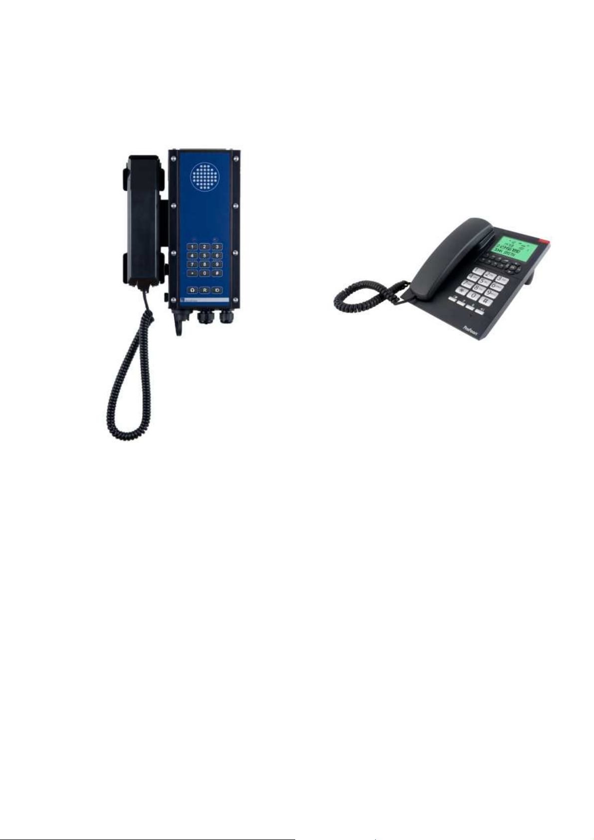
2.2.3 SC411
Full featured f lush mount station with display,
backlight and hands-f ree. Used on bridge and
ECR.
Key f eatures:
Screw less flush mount
Red dimmable backlight
Hands-free operation
Power supply 24V DC
2.2.4 SC421
Full featured water tight station with display,
backlight and hands-f ree. Connect handset
and headset. Used in engine spaces, and on
deck.
Key f eatures:
Water tight
Red dimmable backlight
Hands-free operation
10W speaker dri er
Handset operation
Headset operation
Power supply 24V DC
SeaCom3000 User Manual Page 16 of 94
SeaCom TMN20170417CJ01_0109
2.2.5 SC220
Water tight and salt mist resistant industrial
telephone with call relay build in. Used in
engine spaces and on deck.
Key f eatures:
2 wire only
Handset
Headset
Call ringer relay
2.2.6 Telephones
For dry and heated spaces on board SeaCom
recommend our digital telephone TX325 or the
direct-in/PA enabled SC325 telephone.
They are digital telephones displaying
date/time, caller number and caller name.
They ha e hands-free operation and can be
either wall mounted or desk top mounted.
Note that these telephones are NOT co ered
by the DNV-GL type appro al.
SeaCom3000 User Manual Page 17 of 94
SeaCom TMN20170417CJ01_0109
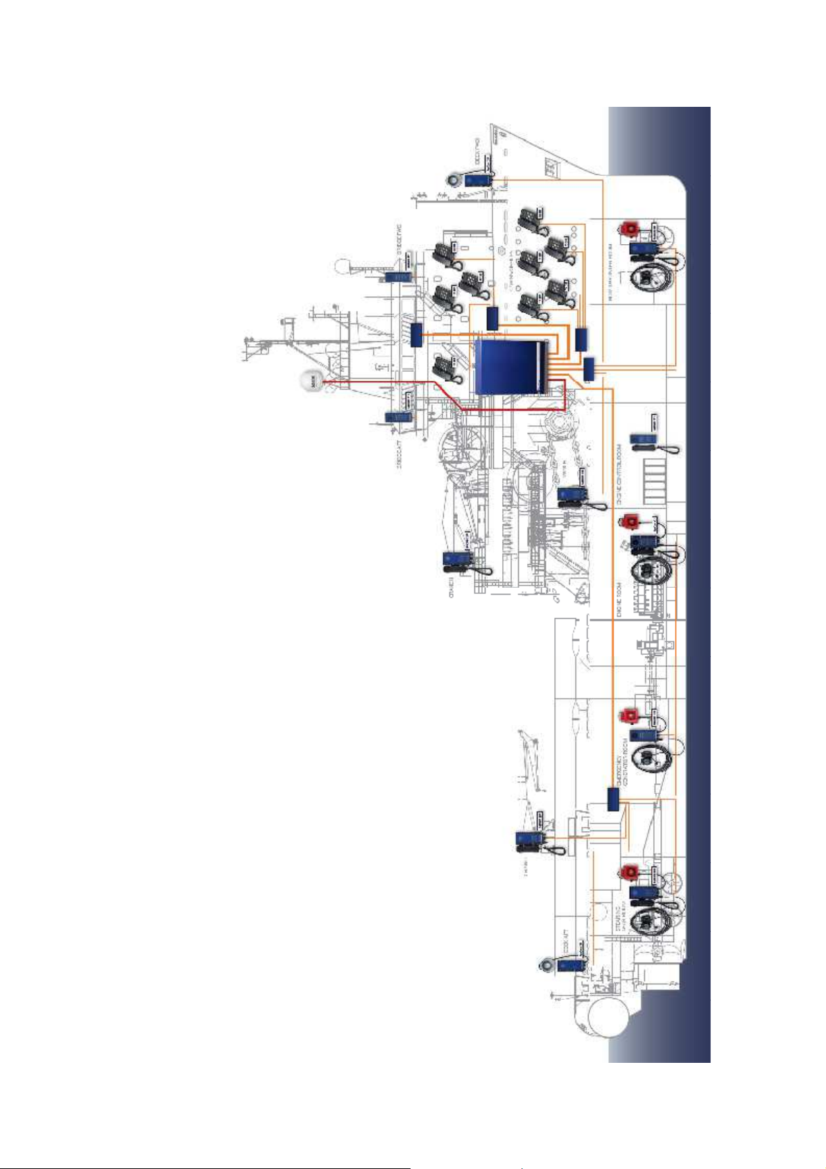
2.3 Typical installation example
The figure shows the architecture of a typical
SeaCom 3000 communication system
installation.
2.4

SeaCom3000 User Manual Page 18 of 94
SeaCom TMN20170417CJ01_0109
3. Designing a system
The intentions of this chapter is to be a guide
to how to design an on board communication
system, how to choose the right system
components, and how to build the exchange
system.
It is to be used by the people who makes
quotations to ship yards and ship owners, as
well as the technicians who is actually
assembling and installing the components.
3.1 Analyzing
All ships ha e dif ferent needs. This is what
makes design and installation of on board
communication challenging. The SeaCom
3000 maritime communication system is a
ery f lexible configurable system which allows
You to meet by f ar the most requirements.
In order to architecture a proper system, You
must first collect information about:
Number of locations that need
communication
The en ironment to be expected at
each location
Type of communication to be carried
out at each location
Number of Satellite lines to be
connected.
3.1.1 Counting locations
The number of locations needing telephones
must be determined. This is done in
cooperation with ship architect and owner.
The number determines the size of the
exchange system to be chosen.
3.1.2 En ironment
On each location, the expected noise le el
must be known, and the location must be
classif ied as protected or exposed, where
protected areas are locations like cabins,
off ices and bridge, whereas exposed will be
areas like engine room, mooring stations or
workshops.
3.1.3 Type of communication
On each location a choice of which kind of
communication is most con enient must be
made. The SeaCom maritime communication
system of fers the below communication styles:
Handset con ersation
Hands-free con ersations
PTT mode (push to talk)
Headset con ersation
Each station can of fer the seamen one or
more of these styles. It is important to select a
style that fits to the needs and which can be
operational in the gi en en ironment f or the
intended use.
3.1.4 Satellite lines
Count how many 2 wire trunk lines will be
needed for connecting satellite communication
equipment.
3.2 Selecting telephones/stations
Based on the analysis, the equipment to be
placed at each location must be selected.
The table below shows typical noise le els to
be encountered on ships.
Location
Noise le el dB
Accommodation
< 60
Bridge
50
-
60
Engine control room
65
-
75
Engine spaces
80
-
100
Steering gear room
100
-
120
Close to engine or generators
100
-
130
The table shall be used as a guide only to
choose among the numerous possibilities
gi en by the SeaCom 3000 maritime
communication system.
The below describes which type of station to
be used in each type of en ironment.
3.2.1 Analogue telephones
Plain analogue telephones are to be used in
protected areas only. The TX325, has the
below operating range:
Hands f ree up to 65 dB noise
Handset con ersations up to 75dB of noise.
3.2.2 SC411
This station gi es the following possibilities in
protected en ironment:
Hands f ree with build in speaker and
microphone up to 75 dB
Hands f ree with external speaker up to
85 db of ambient noise
Push to talk con ersations with external
speaker up to 100 dB of noise.

SeaCom3000 User Manual Page 19 of 94
SeaCom TMN20170417CJ01_0109
Handset con ersations up to 85 dB of
noise.
Operation with headset in up to 120 dB
of noise.
3.2.3 SC211
The talk back station is a station to be used in
exposed en ironment with the below
capabilities:
Push to talk operation up to 100 dB.
Headset operation up to 120 dB of
noise.
3.2.4 SC421
This is the most full f eatured station, to be
used in exposed areas under the below
conditions:
Hands f ree with build in speaker and
microphone up to 75 dB
Hands f ree with external speaker up to
85 db of ambient noise
Push to talk con ersations with external
speaker up to 100 dB of noise.
Handset con ersations up to 85 dB of
noise.
Operation with headset in up to 120 dB
of noise.
3.2.5 SC220
This is a plain analogue telephone with
optional handset or headset. To be used in
exposed areas.
The capability for operation in noisy areas are:
Handset operation up to 85 dB
background noise
Headset operation up to 100 dB of
noise.
3.2.6 Features o er iew
The table below shows the f eatures of the
stations:
Feature
211
220
421
411
Handset connection
Y
Y
Y
Headset connection
Y
Y
Y
Y
Exposed door
option
Y Y Y
Call relay
Y
Y
Y
Y
External speaker
Y
Y
Y
External
microphone
Y Y
Display
Y
Y
Hands free
operation
Y Y
Keys
3
15
21
21
Speed dial
Y
Y
IP class
65
65
65
22
Mounting style
Wall
Wall
Wall
Flush
3.3 Designing the exchange system
The SeaCom 3000 is a scaleable system. It
comes with 24 extension lines and 2 trunk
lines, and can be build up to 144 extensions.
The components used to build the system are:
AEXT16 extension line card
FIO4 trunk line card
CTU2 Cable termination card
CTU24 Cable termination card
PDU Power distribution card
3.3.1 AEXT16
This board adds 8, 16 or 24 extension lines to
the system. Each telephone or
communication station on board requires one
extension line.
3.3.2 FIO4
This board adds 2 or 4 trunk lines to the
system. Trunk lines are used to connect to
satellite terminals, GSM terminals or shore
lines.
3.3.3 CTU2 and CTU24
These boards are used to terminate the ship
cables inside the SeaCom 3000. The CTU2
terminates 16 extension lines and the CTU24
terminates 24 extension lines.
When using the FIO4 board, the 2 or 4 trunk

SeaCom3000 User Manual Page 20 of 94
SeaCom TMN20170417CJ01_0109
lines will occupy the space of 8 extension lines
on the CTU2 or CTU24.
3.3.4 PDU
24V DC has to be distributed to the SC411,
SC211 and SC421 stations in use. The PDU
allows f or this including proper fusing of the
lines. 18 stations can be powered by the
PDU.
3.3.5 Exchange design example
On a ship we ha e f ound out that the below
telephones and stations are required:
4 x SC211
2 x SC411
12 x SC421
4 x SC220
35 x TX325
A total of 57 positions
The SeaCom 3000 comes with 24 extensions,
so we need to add another 33 extension
lines. We choose the AEXT16-24 to add 24
and the AEXT16-16 to add the remaining 9.
Along with the two extra boards, we need a
CTU24 for the additional 24 lines and a CTU2
for the 9 lines.
We ha e 4 + 2 + 12 = 18 positions that require
24V DC, and that can be co ered by adding
one PDU.
3.4 Power considerations
The SeaCom 3000 and the stations are all
powered by 24V DC. This paragraph
describes how to calculate the power required.
3.4.1 Power consumption - exchange
The power needed for the exchange system
can be roughly calculated from the below
formula:
Pexh = 15W + 0.25W * Next
where
Next is the number of extensions installed.
Pexh is the stand by power used by the
exchange.
3.4.2 Power consumption - stations
Except f or the analogue telephones and the
SC220, all the communication stations also
require 24V DC power. The power needed
depends on the actual operation of
communication, where especially the PA calls,
which can engage all stations simultaneously,
must be taken into account, in order to ensure
that the peak power needed can really be
deli ered by the power supply chosen.
A guideline is:
Pstby = 2.0W * Nst
Ppeak = 2.0W * Nst + 22W * Nstpa
Pstby is the idle power used
Ppeak is the peak power used
Nst is the number of stations
Nstpa is the number of stations engaged
in PA calls
3.5 Wiring schematic
Based on the design of the system, it is the
responsibility of the installer to create proper
electrical schematic drawings and
documentation to be used while installing.
This manual is a generic manual, and cannot
be an instruction and the documentation
deli ered to an end user on its own.

SeaCom3000 User Manual Page 21 of 94
SeaCom TMN20170417CJ01_0109
4. Installation
This chapter gi es some guidance in how to
install the SeaCom communication system.
Considerations to be taken, and good practice
to follow. For detailed mechanical drawings
and details on electrical terminals, refer to
later chapters.
4.1 The exchange
The SeaCom 3000 exchange must be located
in a dry entilated space with a maximum
ambient temperature of 55 dgs, the cooler the
longer lif etime shall be expected.
The exchange must be mounted on a
bulkhead in a ertical style to ensure that the
intended air flow can be realized.
Do not mount the exchange horizontal.
The bolts to be used are 6 to 8mm torx or x-
dri e, and should be used like shown on the
following pictures:
4.2 Mounting the stations
The stations are either f lush mount or
bulkhead mount.
4.2.1 Flush mount
SC411 is meant for screw less console flush
mount.
It is important to make a precise cutout, in
order to be able to make the required
electrical isolation between the station and the
steel of the console.
Table of contents
Popular Telephone System manuals by other brands


Nortel
Nortel Business Communications Manager 2.5 Programming guide

Toshiba
Toshiba Strata CIX LVMU Installation and programming guide

BT
BT ULTIMATE 106 user guide

Vodavi
Vodavi Starplus STSe Operation manual

Avaya
Avaya Magic On Hold Messager MP3 Installation & user guide

Ericsson
Ericsson BUSINESSPHONE 6 manual