Bosch B430 User manual
© 2015 Bosch Security Systems, Inc. F.01U.265.454 | 05 | 2015.05
en Installation Guide
Plug-in Telephone Communicator
B430
Bosch Security Systems, Inc.
130 Perinton Parkway
Fairport, NY 14450
USA
www.boschsecurity.com
Bosch Sicherheitssysteme GmbH
Robert-Bosch-Ring 5
85630 Grasbrunn
Germany
Copyright
This document is the intellectual property of Bosch Security Systems, Inc. and is protected by copyright. All rights reserved.
Trademarks
All hardware and software product names used in this document are likely to be registered trademarks and must be
treated accordingly.
Bosch Security Systems, Inc. product manufacturing dates
Use the serial number located on the product label and refer to the Bosch Security Systems, Inc. website at
http://www.boschsecurity.com/datecodes/.
The module uses a green LED to indicate
when the circuit is on or off the hook or
the phone line is ringing. Refer to Table
3.1.
3 | LED descriptions
Use Remote Programming Software
(RPS) or an SDI2 keypad to program
the control panel to use the module for
communication.
For programming parameter
descriptions, options, and defaults refer
to RPS Help or the Program Entry Guide
for your control panel.
4 | Configuration
Flash pattern Function
OFF Steady Standby
ON Steady Line seize
Flash Ring detect
Table 3.1: Diagnostic LED flash patterns
Dimensions 2 in x 3.68 in x 0.60 in
(50 mm x 93.5 mm x 15.25 mm)
Voltage (operating) 12 VDC nominal
Current (maximum) Standby: 24 mA
Alarm: 24 mA
Operating temperature +32°F to +120°F (0°C to +49°C)
Relative humidity 5% to 93% at +90°F (+32°C )
Communication speed 2400 baud maximum
Compatibility B9512G/B9512G-E
B8512G/B8512G-E
B5512/B5512E
B4512/B4512E
B3512/B3512E
6 | Specifications
Region Certification
US UL 365 - Police Station Connected Burglar Alarm Units and Systems
UL 636 - Holdup Alarm Units and Systems
UL 864 - Control Units and Accessories for Fire Alarm Systems
(Commercial Fire)
UL 985 - Household Fire Warning System Units
UL 1023 - Household Burglar Alarm System Units
UL 1076 - Proprietary Burglar Alarm Units and Systems
UL 1610 - Central Station Burglar Alarm Units
FCC Part 15
FCC Part 68
FCC Registration Number: ESVAL00BB430
Ringer Eq: 0.0B
Canada CAN/ULC S303 - Local Burglar Alarm Units and Systems
CAN/ULC S304 - Signal Receiving Centre and Premise
CAN/ULC S545 - Residential Fire Warning System Control
ICES-003 - Information Technology Equipment (ITE)
ULC-ORD C1023 - Household Burglar Alarm System Units
ULC-ORD C1076 - Proprietary Burglar Alarm Units and System
5 | Certifications
2.2 | Wire the module
Installing the module:
1. With the module facing the control
panel as shown below, insert the
support leg into the support hole
labeled X.
2. Align the PCB metal contacts with
the on-board connector.
3. Push the module into place. The
retention clip snaps closed and
secures the module in place.
Figure 2.1: Module installation
Callout ― Description
1 ― Support leg inserted into the
control panel support hole labeled X
2 ― PCB metal contacts resting on
the on-board connector
3 ― Plug-in module retention clip
Connect one end of a compatible
telephone cord to the B430, and
connect the other end to an RJ31X or
RJ38X phone jack that is connected to
the phone line. The module has pads
on both sides of the board to connect
a telephone test set. Refer to Figure
2.2.
Figure 2.2: Wiring the module
Callout ― Description
1 ― Premises telephone
2 ― Incoming Telco line
3 ― Installer telephone test set
4 ― RJ45 phone connector
The B430 Plug-in Telephone Communicator provides communication over the PSTN
(Public Switched Telephone Network) by directly connecting the module to the control
panel. The module provides a single telephone jack and easily installs into an on-board
connector.
You can program, diagnose, and troubleshoot the system from the control panel keypad
as well as remotely through RPS.
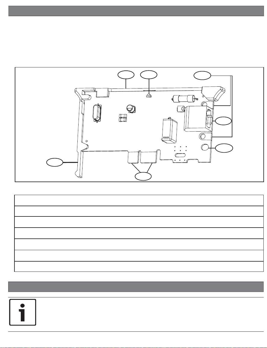
Callout ― Description
1 ― Module handle and support leg
2 ― Line seize/ring LED
3 ― Test phone pads
4 ― RJ45 phone connector
5 ― Plug-in module retention clip opening
6 ― PCB metal contacts
Figure 1.1: Module overview
NOTICE!
Remove all power (AC and battery) before making any connections. Failure to
do so might result in personal injury and/or equipment damage.
2 | Install or remove the module
2.1 | Install the module
The control panel communicates with
and provides power to the module
through the plug-in connection. Proper
installation results in the necessary
electrical and mechanical connection.
1 | Overview
To remove an installed module, hold the
plug-in module retention clip open with
one hand while grasping the top corners
of the module support handle with your
other hand. Pull the module out.
2.3 | Remove the module
123
4
5
6
1

2.2 | Wire the module
Installing the module:
1. With the module facing the control
panel as shown below, insert the
support leg into the support hole
labeled X.
2. Align the PCB metal contacts with
the on-board connector.
3. Push the module into place. The
retention clip snaps closed and
secures the module in place.
Figure 2.1: Module installation
Callout ― Description
1 ― Support leg inserted into the
control panel support hole labeled X
2 ― PCB metal contacts resting on
the on-board connector
3 ― Plug-in module retention clip
Connect one end of a compatible
telephone cord to the B430, and
connect the other end to an RJ31X or
RJ38X phone jack that is connected to
the phone line. The module has pads
on both sides of the board to connect
a telephone test set. Refer to Figure
2.2.
Figure 2.2: Wiring the module
Callout ― Description
1 ― Premises telephone
2 ― Incoming Telco line
3 ― Installer telephone test set
4 ― RJ45 phone connector
The B430 Plug-in Telephone Communicator provides communication over the PSTN
(Public Switched Telephone Network) by directly connecting the module to the control
panel. The module provides a single telephone jack and easily installs into an on-board
connector.
You can program, diagnose, and troubleshoot the system from the control panel keypad
as well as remotely through RPS.
Callout ― Description
1 ― Module handle and support leg
2 ― Line seize/ring LED
3 ― Test phone pads
4 ― RJ45 phone connector
5 ― Plug-in module retention clip opening
6 ― PCB metal contacts
Figure 1.1: Module overview
NOTICE!
Remove all power (AC and battery) before making any connections. Failure to
do so might result in personal injury and/or equipment damage.
2 | Install or remove the module
2.1 | Install the module
The control panel communicates with
and provides power to the module
through the plug-in connection. Proper
installation results in the necessary
electrical and mechanical connection.
1 | Overview
To remove an installed module, hold the
plug-in module retention clip open with
one hand while grasping the top corners
of the module support handle with your
other hand. Pull the module out.
2.3 | Remove the module
123
4
5
6
1
© 2015 Bosch Security Systems, Inc. F.01U.265.454 | 05 | 2015.05
en Installation Guide
Plug-in Telephone Communicator
B430
Bosch Security Systems, Inc.
130 Perinton Parkway
Fairport, NY 14450
USA
www.boschsecurity.com
Bosch Sicherheitssysteme GmbH
Robert-Bosch-Ring 5
85630 Grasbrunn
Germany
Copyright
This document is the intellectual property of Bosch Security Systems, Inc. and is protected by copyright. All rights reserved.
Trademarks
All hardware and software product names used in this document are likely to be registered trademarks and must be
treated accordingly.
Bosch Security Systems, Inc. product manufacturing dates
Use the serial number located on the product label and refer to the Bosch Security Systems, Inc. website at
http://www.boschsecurity.com/datecodes/.
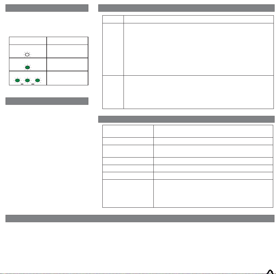
The module uses a green LED to indicate
when the circuit is on or off the hook or
the phone line is ringing. Refer to Table
3.1.
3 | LED descriptions
Use Remote Programming Software
(RPS) or an SDI2 keypad to program
the control panel to use the module for
communication.
For programming parameter
descriptions, options, and defaults refer
to RPS Help or the Program Entry Guide
for your control panel.
4 | Configuration
Flash pattern Function
OFF Steady Standby
ON Steady Line seize
Flash Ring detect
Table 3.1: Diagnostic LED flash patterns
Dimensions 2 in x 3.68 in x 0.60 in
(50 mm x 93.5 mm x 15.25 mm)
Voltage (operating) 12 VDC nominal
Current (maximum) Standby: 24 mA
Alarm: 24 mA
Operating temperature +32°F to +120°F (0°C to +49°C)
Relative humidity 5% to 93% at +90°F (+32°C )
Communication speed 2400 baud maximum
Compatibility B9512G/B9512G-E
B8512G/B8512G-E
B5512/B5512E
B4512/B4512E
B3512/B3512E
6 | Specifications
Region Certification
US UL 365 - Police Station Connected Burglar Alarm Units and Systems
UL 636 - Holdup Alarm Units and Systems
UL 864 - Control Units and Accessories for Fire Alarm Systems
(Commercial Fire)
UL 985 - Household Fire Warning System Units
UL 1023 - Household Burglar Alarm System Units
UL 1076 - Proprietary Burglar Alarm Units and Systems
UL 1610 - Central Station Burglar Alarm Units
FCC Part 15
FCC Part 68
FCC Registration Number: ESVAL00BB430
Ringer Eq: 0.0B
Canada CAN/ULC S303 - Local Burglar Alarm Units and Systems
CAN/ULC S304 - Signal Receiving Centre and Premise
CAN/ULC S545 - Residential Fire Warning System Control
ICES-003 - Information Technology Equipment (ITE)
ULC-ORD C1023 - Household Burglar Alarm System Units
ULC-ORD C1076 - Proprietary Burglar Alarm Units and System
5 | Certifications

© 2015 Bosch Security Systems, Inc. F.01U.265.454 | 05 | 2015.05
en Installation Guide
Plug-in Telephone Communicator
B430
Bosch Security Systems, Inc.
130 Perinton Parkway
Fairport, NY 14450
USA
www.boschsecurity.com
Bosch Sicherheitssysteme GmbH
Robert-Bosch-Ring 5
85630 Grasbrunn
Germany
Copyright
This document is the intellectual property of Bosch Security Systems, Inc. and is protected by copyright. All rights reserved.
Trademarks
All hardware and software product names used in this document are likely to be registered trademarks and must be
treated accordingly.
Bosch Security Systems, Inc. product manufacturing dates
Use the serial number located on the product label and refer to the Bosch Security Systems, Inc. website at
http://www.boschsecurity.com/datecodes/.
The module uses a green LED to indicate
when the circuit is on or off the hook or
the phone line is ringing. Refer to Table
3.1.
3 | LED descriptions
Use Remote Programming Software
(RPS) or an SDI2 keypad to program
the control panel to use the module for
communication.
For programming parameter
descriptions, options, and defaults refer
to RPS Help or the Program Entry Guide
for your control panel.
4 | Configuration
Flash pattern Function
OFF Steady Standby
ON Steady Line seize
Flash Ring detect
Table 3.1: Diagnostic LED flash patterns
Dimensions 2 in x 3.68 in x 0.60 in
(50 mm x 93.5 mm x 15.25 mm)
Voltage (operating) 12 VDC nominal
Current (maximum) Standby: 24 mA
Alarm: 24 mA
Operating temperature +32°F to +120°F (0°C to +49°C)
Relative humidity 5% to 93% at +90°F (+32°C )
Communication speed 2400 baud maximum
Compatibility B9512G/B9512G-E
B8512G/B8512G-E
B5512/B5512E
B4512/B4512E
B3512/B3512E
6 | Specifications
Region Certification
US UL 365 - Police Station Connected Burglar Alarm Units and Systems
UL 636 - Holdup Alarm Units and Systems
UL 864 - Control Units and Accessories for Fire Alarm Systems
(Commercial Fire)
UL 985 - Household Fire Warning System Units
UL 1023 - Household Burglar Alarm System Units
UL 1076 - Proprietary Burglar Alarm Units and Systems
UL 1610 - Central Station Burglar Alarm Units
FCC Part 15
FCC Part 68
FCC Registration Number: ESVAL00BB430
Ringer Eq: 0.0B
Canada CAN/ULC S303 - Local Burglar Alarm Units and Systems
CAN/ULC S304 - Signal Receiving Centre and Premise
CAN/ULC S545 - Residential Fire Warning System Control
ICES-003 - Information Technology Equipment (ITE)
ULC-ORD C1023 - Household Burglar Alarm System Units
ULC-ORD C1076 - Proprietary Burglar Alarm Units and System
5 | Certifications
Other manuals for B430
2
Table of contents
Other Bosch Telephone System manuals


