Seagate ST41201K User manual

<555>seagate
Elite
Disc
Drive
ST41201K
User's
Manual
(/Pl
Interface)

Contents
Preface...........................................................................
:~....................
iii
Electrostatic discharge protection ............................
..
....................... iii
Important safety information and precautions.................................... iv
Technical support services ............................................................... vi
Section
1.
General description ........................................
..
.................... 1
Section
2.
Installation ...................
..
.......
....
.
..
.
....
.
..
..
..
..............
..
...
...
...... 7
Section
3.
Operation.............................................................................
33
Section
4.
Parts data ..............
...
.......
..
.
..
....
......
..
.....
..
....
..
.........
...
.....
..
... 37
Section
5.
Mainienance ........................................................................
© 1992 Seagate Technology, Inc. All rights reserved
Publication Number: 83327320,
Rev.
B
Seagate®,SeagateTechnology®,andtheSeagatelogoareregisteredtrademarks
of
SeagateTechnology, Inc. Elite™·SeaFAX™,SeaFONE™,andSeaBOARD™
aretrademarksofSeagate Technology, !nc. Otherproduct namesare registered
trademarks
or
trademarks
of
their
ovJners.
No part of this publication may be reproduced in any form without wri'
permission from Seagate Technology, Inc.

ST
41201
K
User's
Manual iii
Preface
This manual contains information for users of the Seagate ST41201K Elite disc
drives (employing the IPI interface).
It
provides instructions to all personnel
who
operatethe drive and to customer engineers who install and check out
the
drive.
Additionalinformationisavailableinthereferencemanual(publication83327330).
Electrostatic discharge protection
Caution. Removal
of
circuitboards by personnel not performing depot repairwill
damage components and may void the warranty.
'\II drive electronic assemblies are sensitive to static electricity
due
to
the
ectrostatically sensitive devices used within the drive circuitry.
Although
somedevicessuch as metal-oxidesemiconductors are extremelysensitive, all
semiconductors, as well as some resistors and capacitors, may
be
damaged
or degraded by exposure to static electricity.
Electrostatic damage to electronic devices may be caused
by
the
direct
discharge
of
acharged conductor,
or
by exposuretothe static fields
surround-
ing charged objects. To avoid damaging drive electronic assemblies,
observe
the following precautions when servicing the drive:
• Ground yourself to the drive whenever the drive electronics are
or
will
be
exposed. Connectyourselfto ground with a wrist strap (refer to accessories in
section4forthepartnumber). Connection maybemadeto anygrounded metal
assembly. As ageneral rule, rememberthat you and the driveelectronics must
all be grounded to avoid potentially damaging static discharges.
• Turn off power before removing or installing the DC power cable.
• Do not remove any circuit boards from the drive.
• Never use an ohmmeter
on
any circuit boards.

iv
Important safety information and precautions
Caution.
Use
forced-air ventilation
when
bench-testing the drive
to
ensure
proper cooling
of
drive components.
Use proper safety and repair techniques for
safe,
reiiabie
operation
of
this
unit.
Service
should
be
done
only
by
qualified
persons.
We
recommend
theprocedures
in
thismanual
as
effective
ways
of
servicingthe
unit.
Some
proceduresrequirethe
useofspecialtools. Forpropermaintenance
and
safety,
you
must
use
thesetools
as
recommended.
The procedures
in
this
manual
contain
warnings
and
cautions that
must
be
carefully
read
and
followed
to
minimize
oreliminate
the
risk
of
personal
injury.
The
warnings point out conditions or practices
that
may
endanger
you
or
others.
..,.
cautions point out conditions or practices
that
may
damage
the
unit, possk ,
making
it
unsafe for
use.
You
must
also
understand
that
these
warnings
and
cautions
are
not
exhaustive.
We
cannot possibly
know,
evaluate,
and
advise
you
of
all
the
ways
in
which
maintenance might
be
performed orthe possible
risk
of
each
technique. Conse-
quently,
we
have
not
completed any
such
broad
evaluation. If
you
use
a
non-
approved procedure or
tool,
first
ensure
that
the
method
you
choose
will
not
risk
either your
safety
or unit performance.
Ahri1ays
observ'e
the
follovving
vvarnings
and
precautions:
• Perform
all
maintenance
by
following
the
procedures
in
this
manual.
• Follow
all
cautions
and
warnings
in
the procedures.
Use
sound
safety practices
when
operating or repairing
the
unit.
•
Use
caution
when
troubleshooting a unit
that
has
voltages
present.
Remove
power
from
the
unit
before servicing
it.
• Wear safety
shoes
when
removing
or
replacing
heavy
parts.
• Provide a
means
to isolatethedrive
from
the
main
power
in
case
of
fire orother
emergency.
• Ensure that the internal temperature
of
the
rack
or
cabinet
will
not
exceed
the
limitsdefined for the drive,
when
the drive
is
mounted
in
an
equipment rack
or
cabinet.
When
units
are
stacked
vertically,
pay
special
attention
to
the
top
where
temperatures
are
usually
highest.
Follovv
the
piecautions
listed
undei
"Electiostatic
dischaige
piotection"
above.
•
Do
not
remove
any
circuit
boards
from
the
drivechassis.
Return
the entiredrive
for depot repair if
any
circuit
board
is defective.
Removal
of
circuit boards '
personnel
not
performing depot repair
will
damage components
and
may
VL
the
warranty.

ST41201 K
User's
Manual
v
• Do not remove the head and disc assembly (HOA) from the drive chassis.
Return the entire drive for depot repair if the HOA is defective.
• Do not attemptto disassemble the HOA.
It
is not field repairable. If
the
sealed
HOA is opened by personnel not performing depot repair, this will damage
components and void the warranty.
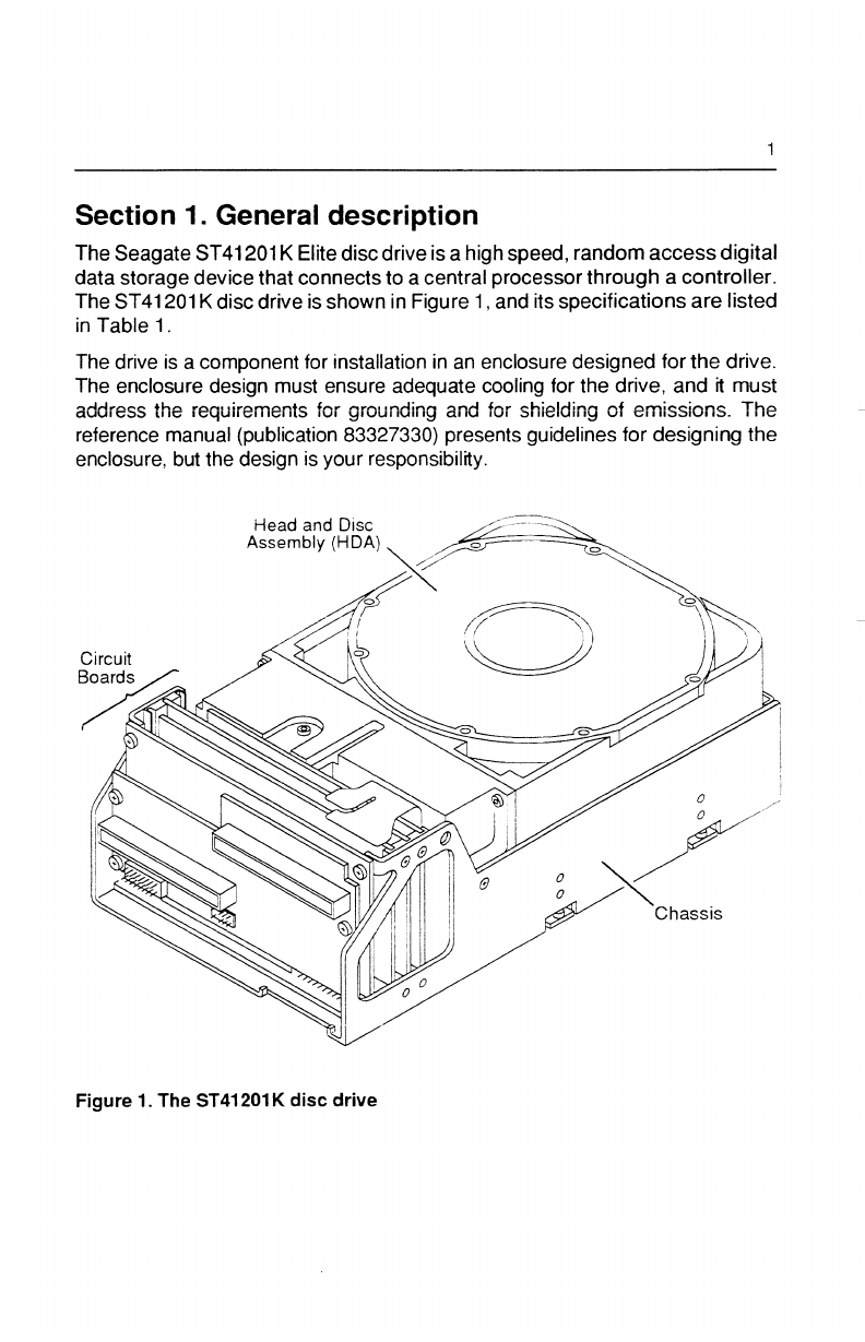
• As a component, this drive is designed to be installed
and
operated in
accordance wnh UL1950, IEC950, EN60950, CSAC22.2950. and VDE0806.
• Always de-energize the drive before removing
or
installing cables.
• Ensure that the power supply meets the specifications
in
this manual and is
designed to be used
in
accordance with
Ul1950,
IEC950, EN60950,
CSA
C22.2 950, and VDE0806.
..:ieagate takes all reasonable steps to ensure that its products are certifiable to
currently accepted standards. Typical applications of these disc drives include
customerpackaging and subsystemdesign Safety agenciesconditionally certify
component parts, such asthe
Eme
disc drive, basedon theirfinal acceptability in
the end-useproduct. Thesubsystemdesignersare responsible formeetingthese
conditions of acceptability
in
obtaining safety/regulatory agency compliance in
their end-use products and
in
certifying where required by iaw. A necessary part
ofmeeting safetyrequirements istheprovision forovercurrentprotectionon drive
SELV supply voltages.
This unn is a component assembly and as such is not meantto comply with FCC
orsimilar national requirements as a stand-alone unn. Engineering radiated and
conducted emissions test results are available through the Seagate Safety
Department to assist the subsystem designer.

vi
Technical support services
Seagate Technology
provides
technical
support
literature
and
diagnostic
util~ies
to authorized distributors.
Please
contact
your
dealer for technical support
and
installationtroubleshooting.
Product
technical
support
is
available
for
all
Seagate
products
by
calling
the
SeaFAX,
SeaFONE,
or
SeaBOARD
services.
These
are
toll calls
if
you
dial
from
outside
of
the
number's
local
dialing
area.
SeaFAX: (408) 438-2620
You
can
use a Touch-Tone telephone
to
access
Seagate's automated
FAX
delivery
system
and
select
technical
support
information by
return
FAX.
This
service
is
available twenty-four
hours
a
day,
seven
days a
week.
SeaFONE: (408) 438-8222
Theenhanced
phone
system
provides
recorded
technicalinformation
on
select1:._
Seagate products
while
you
are
on
hold.
Technical
support
specialists
are
available to answer questions
from
8:00
A.M. to
5:00
P.M.
PST,
Monday through
Friday. Recordings
are
accessibletwenty-four hours a
day,
seven
days a
week.
SeaBOARD:
TheSeagateTechnical Support
Bulletin
Board
System
(BBS)
is
available
twenty-
four hoursa
day,
seven
days a
week.
A
modem
is
required
to
access
this
service.
The communications software
must
be
set
for
eight
data
bits
no
parity
and
one
stop bit
(8N1
).
With
this
service
you
can
access:
• Specifications
and
jumper configurations for
all
Seagate products
• Reprints of Seagate documentation
• Adirectory
of
information
and
helpful
utilitiesthat
you
can
downloadto your
own
computer
Location Telephone Number Maximum Baud Rate
United States/Canada
(408)
438-8771
9600
England
44-62-847-8011
9600
Germany
49-89-140-9331
2400
Singapore
65-227-2217
9600
Australia
61-2-
756-2359
9600
Note. This
is
a
toll
call
if
you
dial
from
outside
of
the
number's
local
dialing
area.

Section 1. General description
The Seagate ST41201 K Elitediscdriveisa high speed, random
access
digital
data storage devicethat connects to a central processor through a controller.
The
ST
41201 K disc drive is shown in Figure 1, and its specifications
are
listed
in
Table 1.
The drive is a component for installation
in
an enclosure designed for
the
drive.
The enclosure design must ensure adequate cooling for the drive, and it must
address the requirements for grounding and for shielding of emissions. The
reference manual (publication 83327330) presents guidelines for designing the
enclosure, but the design is your responsibility.
Figure 1. The ST41201K
disc
drive

2
Table 1. Drive specifications
Characteristics Conditions Specifications
Size Dimensions (see "Space
requirements"
in
section
2)
Weight
4.1
kg
(9.0 lb)
(drive only)
Weight
(power supply only)
Interface IPl-2
Recording
Transfer rate
Total capacity
(unformatted)
Bytes pertrack
(unformatted)
Number of discs
Movable data heads
Servo heads
Physical heads
per surface
Cylinders per
headidisc assy
Modulation
Disc speed
at
5400
RPM
2.3
kg
(5.0 lb)
1,200,055,000 bytes
33,599
10
17
2101* (0-2100 logical)
2,?code
24.2 MHz (3.0 Mbytes/sec)
• Users normally reserve two cylinders fordiagnostic use (cylinder 2100 for defect
map and cylinder 2099 for diagnostics); however, both cylinders can be used for
customer data if desired.
continued

General description
continued from previouspage
Characteristics
Conditions
Specifications
Seek time
(time required to move heads
to
a different track address) Typical full 22.5 msec
max
Typical average
11
.5 msec max
Typical one-track 1.7 msec max
Latency
(time required to reach a
particular track address after
head positioning
is
complete) Average 5.55 msec
(disc rotation
at
5400 RPM)
Maximum 11.17 msec
(disc rotation
at
5373 RPM)
Start time**
60
sec max
Stop time
60
sec max
** Following the powersequence delay, once
DC
power
is
applied and start
conditions are present.
3
The drive contains all the circuits and mechanical devices necessary to record
data on and recover it from its discs. The drive requires DC voltage inputs from
an external power supply, which receives its AC input powerfrom
the
site main
power source. A powersupply and DC power cable are available accessories.
Thedriveconsists
of
a head and disc assembly(HDA) and several circuit boards
mounted on a common chassis. The circuit boards contain
the
electronics
required for drive operation. The HOA is a sealed unit containing
the
electrome-
chanical components used for data storage and retrieval.
These
components
include the discs, spindle, drive motor, actuator, and heads.
The ten discs provide the recording medium for the drive. These discs
are
mounted on a spindle, and the spindle is coupled directlyto the drive motor.
The
drive motor rotates the discs at 5400 RPM and also produces a circulation of air
within the sealed HOA.

4
All
functions
performed
by
the
drive
are
done
underdirection ofthecontroller.
As
shown
in
Figure
2,
the
controiier communicates
with
the drive
via
the
interface
whichconsists
of
a
number
of
1/0
lines
carrying
the
necessary
signalsto
and
from
the drive.
Refer
to
the reference
manual
for adescription
of
interface functions.
Some interface
lines,
including
those that
carry
commands
to
the
drive,
are
not
enabled
unless
the
drive
is
selected
by
the
controller.
Unit
selection
allows
the
controller,
which
can
be
connected
to
more
than
one
drive,
to initiate
and
direct
an
operation
on
a specific
drive.
IH
Data recorded
in
concentric tracks
Unit
Selection
Logic
Head
Selection
Logic Heads
Read/Write
t---~
Logic I
~
~
Seek
Logic
Track
Orientation
Logic
Error
Detection
Logic
Positioning
~
Devloe
If
< > Discs
Power Supply
Figure
2.
Drive functional
block
diagram

General description 5
All driveoperationsare related to data recovery and storage (normally referred to
asreading and writing). Theactual reading and writing is performed byheadsthat
are positioned overthe rotating discs' recording surfaces. There is
one
head for
each data surface. The heads are positioned
in
such a way that
data
is
written
in
concentric tracks around the disc surfaces (see Figure 2).
Before any read
or
write operation can be performed,
the
controller
must
instruct the drive to position the heads over the desired
cylinder
(called
seeking) and usethehead located overthe surface (head selection)
where
the
operation is to be performed.
The heads are mounted on the actuator, and the actuatormoves
the
heads
over
the rotating discs. There are 18
heads-a
servo head to sense actuator
,ositioning and 17 data heads used for datatransfersto and from
the
discs. The
actuator has avoice coil that moves
in
apermanent magneticfield in response to
signals from the servo positioning circuitry. The voice coil moves
the
heads in an
arc acrossthe rotating discs.
When the drive is not powered on, the heads rest on the disc surface in the
preassigned landing zone (beyond the data zone). The actuator automatically
iatches
in
thisposition, to protectthedrive
in
the eventthat
it
is moved
or
shipped.
When the drive is activated to bring the discs up to speed,
the
heads
fly on a
cushion of air close to the disc surface.
After arriving at the data track and selecting a head, the controller locates
the
portion of the track where the data is to be read
or
written. This is called track
orientation. Signals from the drive indicate the beginning
of
each track.
The
controller uses these signals to determinethe position ofthe head on
the
track.
When the head is above the desired track location, the controller
commands
the
driveto actuallyreadorwritethedata. During aread operation,
the
driveretrieves
data from the discs, processes
it,
and transmits it to thecontroller. Duringa write
operation, the drive receives data from the controller, processes it, and stores it
on the discs.
The drive can also recognize certain errors that may occur during its operation.
When
an
error is detected, status information is available through
the
controller.


7
Section
2.
Installation
The information contained
in
this section describes installation and initial
checkout of the drive.
Site requirements
The site requirements considered are environment, airflow, space, power,
grounding, and interface.
Environmental requirements
Table 2 lists
all
environmental requirements for the drive.
fable
2.
Environmental
requirements
Conditions
Operating environment
Temperature
Humidity
Barometric pressure
Non-operating environment
(unpacked)
Temperature
Humidity
Barometric pressure
Storage environment (packed)
Temperature
Humidity
Barometric pressure
Transit environment (packed)
Temperature
Humidity
Barometric pressure
Specifications
Range of 10°C to 45°C (50°F
to
113°F) with a
maximum change of 15°C (27°F)
per
hour
Range of 20% to 80% relative
A maximum wet bulb temperature of 26°C (79°F)
-305 m to 2,000 m (-1,000 ft to
6,560
ft)
104 kPa to 79 kPa (30 in Hg to
23
in Hg)
Range of 10°C to 45°C (50°F to 113°F) with a
maximum change of 15°C (27°F)
per
hour
Range of 20% to 80% relative
A maximum wet bulb temperature of 26°C (79°F)
-305 m to 3,000 m (-1,000 ft to
10,000
ft)
104 kPa to 69 kPa (30 in Hg to
20
in Hg)
Range of
-10°c
to 50°C (14°F to 122°F) with a
maximum change of 15°C (27°F)
per
hour
Range of
5%
to 95% relative
-305 m to 3,000 m (-1,000 ft to
10,000
ft)
104
kPa to 69 kPa (30 in Hg to
20
in Hg)
Range of -40°C to 60°C (-40°F
to
140°F) with a
maximum change of 20°C (36°F)
per
hour
Range of
5%
to 95% relative
-305 mto 12,192 m(-1,000 ft to
40,000
ft)
104 kPa to 19 kPa (30 in Hg to 6 in Hg)

8
Airflow
requirements
The enclosure design
must
ensure
adequate
cooling forthe drive.
Note
that the
fan
in
tile power supply cools only the power supply's internal
parts.
The drive's product specification (document 64403104) describes how to
evaluatethe airflow design. The evaiuation consists of ensuring that the case
temperatures of certain critical components remain within acceptable limits
during drive operation.
We
recommendorienting
the
driveordirectingtheairflow
in
a
way
that
createsthe
leastamount
of
airflow
resistance
while providing airflow
above
the
circu~
boards
andaroundthe
head
and
discassembly
(HDA).
Also,
choosetheshortestpossible
pathbetweentheair
inlet
and
exit.
This minimizesthedistancetraveled
by
airtt'
is heated
by
the drive
and
by other
nearby
heat
sources.
Figure 3 shows the design approach
with
one
or
more
fans
used
to
generate
airflow.
The
airflow patterns
can
be
created
by
thefans eitherpushing ordrawing
air.
It
is
possible
to
install
a pair
of
drives side-by-side
so
that the air circulation
created
by
one
or more fans ventilates
both
drives.
Figure4
shows
the design approach
when
the airflowpattern
is
from
fronttoback
orfrom
back
to
front.
Baffles
can
redirect aportionofthe airflowthroughthe space
between the circuit
boards.

Installation
ISingle Drive I
·······>·· ...................................... ········>
·················>················ ········>
................................................ ········>
.........................................................
--·
......
·>
Airflow between
circuit boards
- - • Airflow above and below
head and disc assembly
(HDA)
--·
--·
--·
Pair of Drives
9
.................................................................................................................
........... ................................... ................ ................................... ········>
...............................................................................................................
...........
....................................
................
....................................
....
···>
0
--·
-->--
--·
0---~--
--·
o
~
----->-----
Figure 3. Perpendicular airflow

10
IFront-to-Back Airflow I
__
..
__
I0
__
Go-·--~-
:
~1-~f'-J
·-1----·---
---->-
'---
__
....,....
---
t->-1-1~\~~
~
LI
->------
..
I
'--i:l·;~r
Ill
~
ro:
I
~
1r
l I
11)\
rn/
I
~1v1:
1~11:
I
-
-·--tr\""\:
--->----
-);?'-t->-
--tr.If.
tHtt-:-t----->---
l~~
I
llLltllJ;
I
········> Airflow between
circuit boards
- - + Airflow above and below
head and disc assembly (HDA)
FiQure 4. Lengthwise airflow
n_u1_\·~
.
.-··
..
.":·~·~:.:.:.:t.:.:_:_:_:_:.~.:.:_:_:_:.~.:ii,.::
Dd.111~
"•••••·······~·············>-······

Installation
11
Space requirements
The drive is designed to be mounted
in
one of the three orientations shown in
Figure5. Thedrivemaybe mountedon its base
or
on eitherside.
The
physical
dimensions
of
the driveand optional power supply are shown in Figure 6.
The
drive itself weighs
4.1
kg (9.0 lb).
Fordetailsaboutdesigning
an
enclosuretomatchthedrivemountingdimensions,
refer to the drive's product specification.
Figure 5.
Mounting
orientations

12
Figure
6.
Dimensions
of
the
drive

Installation
13
Power requirements
The voltage and current requirements for a single drive are shown in
Table
3
below. Consulttheproductspecification before selecting ordesigninga
power
supplyforthedrive. The product specification presents more detailed require-
ments including the types of overvoltage and overcurrent protection needed.
AC power requirements for the optional Seagate power supply
are
listed in
Table
4.
Conversion to the different line voltages is explained in the installation
procedures.
Table
3.
DC
power
requirements
for
the
drive
Current
Seeking Maximum
and Power
Voltage Idle
2.7A
2.0A
Reading Seeking
+5
v
+12V
3.1
A 2.7A
2.3A 2.6A
Watts
38
w
43
w
Maximum Current
Limits
Maximum operating current*
Average idle current
Maximum starting current*
Maximum seek current
45
w
+5
v
3.7A
2.7A
2.7A
2.7A
Continuous
Reading
3.7 A
2.0 A
43
w
+12V
2.9 A
2.0 A
5.4 A
3.7 A
*Instantaneous+
12
V current peaks will exceed these values by up to 0.8
A.
Table
4.
AC
power
requirements
for
the
power
supply
Nominal Values
Specifications 100-120 VAC
208-240VAC
Voltage range
85
to 132 V
175
to 264 V
Nominal line frequency 50/60
Hz
50/60
Hz
Frequency range 48.0 to 62.0 Hz 48.0 to 62.0 Hz
Phase requirements single phase single phase
Power consumed*
65W 63W
Line current*
0.90A
0.56A
Power factor*
0.61
0.54
*Measured
at
nominal values when discs are rotating and carriage is track-following.

14
Grounding requirements
A safety ground must
be
provided
by
the site AC powersystem. The green wire
(orgreen wirewithyellowstripe)
in
the
AC powercord provides
the
safetyground
connectionbetweenthepowersupplyandthesiteAC powersystem.
The
siteAC
power
system must provide the safety ground
to
earth ground connection.
All site AC power connection points, including convenience outlets for test
equipment,
must
be
maintained at the
same
safety
ground
potential.
Interface requirements
This
driveisatwo-portdevice, so it can be shared
by
two controllersifnecessary.
It
is
designed
to
be
connected in a daisychain 1/0 configuration
as
shown
·
Figure
7. Table5 showsthepin assignments and signal namesforthe 1/0cabi.
Detailed information about interface lines is given in
the
reference manual
(publication 83327330}.
The
two
1/0 connectors at
the
back
of
the
drive
accept
the
1/0
cables
that
connect
itto
thesystem.
J31
(port
A)
and
J32
(port B)
arethe
connectors
to
which
daisychain 1/0cables are attached. Eachdaisychaincable isa continuouscable
having one connector for each drive
it
connects to.
~
Port A
--~--
Pert B
---+--
Terminator
Terminator
lp.---C-cnt-rci!e-r
--.~
'----.-----'
Figure
7. Daisychain
configuration
Other manuals for ST41201K
1
Table of contents