WI
NDING
KN OB
SPECIAL
NOTE
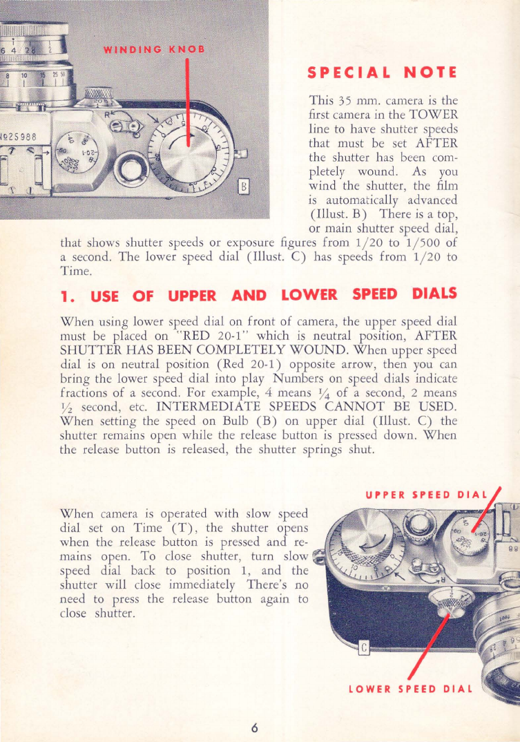
This
35
mm. camera
is
the
first camera in the
TOWER
line to have shutter speeds
that must
be
set AFTER
the shutter has been
com-
pletely wound. As you
wind the shutter, the film
is
automatically advanced
(Illust.
B)
There
is
a top,
or main shutter speed dial,
that shows shutter speeds or exposure figures from 1/
20
to 1/ 500
of
a second. The lower speed dial (Illust.
C)
has speeds from 1/
20
to
Time.
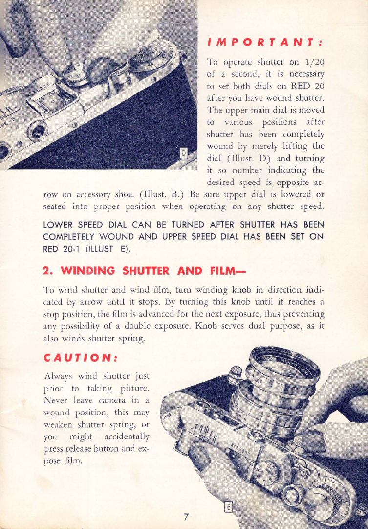
1.
USE
OF
UPPER
AND
LOW£R
SPEED
DIALS
When using lower speed dial on front
of
camera, the upper speed dial
must
be
placed on "RED 20-1" which
is
neutral position, AFTER
SHUTTER HAS BEEN COMPLETELY
WOUND.
When
upper speed
dial
is
on neutral position (Red 20-1) opposite arrow, then you c
an
bring the lower speed dial into play Numbers on speed dials indicate
fractions
of
a second. For example, 4 means
Y4
of a second, 2 means
Yz
second,
etc.
INTERMEDIATE
SPEEDS
CANNOT
BE USED.
When
setting the speed on Bulb
(B)
on upper dial (Illust. C) the
shutter remains open while the release button
is
pressed down.
When
the release button
is
released, the shutter springs shut.
When
camera
is
operated with slow speed
dial set on Time
(T)
, the shutter opens
when the release button
is
pressed and
re-
mains open. To close shutter, turn slow
speed dial back to position 1, and the
shutter will close immediately There's no
need to press the release button again
to
close shutter.
6