Secced SC-Video-10/100VP Manual

Ares 3 system
Operators Guide
Professional Fluid Head & Tripod
SC-Video-10/100VP
SC-ENG/CF 100M
Read this first before using and save it
www.secced.com

Copyright Beijing Secnovo Co., Ltd 2007
All right reserved throughtout the world. No part of this document may be stored in a retrieval system,
transmitted, copied or reproduced in any way including, but not limited to, photocopy, photograph,
magnetic or other record without the prior agreement and permission in writing of
Beijing Secnovo Co., Ltd
Secced is registered trademark of Beijing Secnovo Co., Ltd
Printed in People Republic of China by Secnovo, Beijing.
C
Ares 3
Fluid Head & Tripod
SC-Video-10/100VP
SC-ENG/CF 100M
Fluid Head Page 3
Tripod Page 15
Mid-level Spreader Page 26
Page 22Floor spreader
Safety – Read this first
Warning Symbols in this Operators Guide
Where there is a risk of personal injury, injury to others, or damage to the Ares 3
system or associated equipment, comments appear, highlighted by the word.
WARNING! And supported by the warning triangle symbol.
1
Technical Data
Further information
For further information or advice regarding this Ares 3 system, please contact
Beijing Secnovo Co., Ltd or your local distributor.
For full details on maintenance and spare parts, please refer to the Ares 3 system
Maintenance Manual and Illustrated Parts List. This is obtainable from
Beijing Secnovo Co., Ltd or your local distributor.
www.secced.com
Fluid Head
Tripod
Weight(complete with pan bar and bowl clamp) 3 kg / 6.6 lb
Payload range 5 to 10kg / 11 to 22lb
Counterbalance 0 to 4 step
Blance plate 60mm
Grades of drag
Horizontal 0 to 3 grades
Vertical 0 to 3 grades
Tilt range -75 to +90 under maximum payload capacity
Diameter of bowl 100mm
Weight 3.9kg / 8.6lb
Payload capacity 40kg / 88lb
Height 40-150cm

2
Introduction
The Ares 3 system include SC-Video-10/100VP fluid head, SC-ENG/CF 100M tripod,floor spreader
and padded bag.
The SC-Video-10 /100VP embodies 5 steps counterbalancing mechanism and the adjustable drag
aseemblies for pan and tilt motions.
The balance system is easily adjusted by a knob on the right-hand side of the head. The drag
system ensures smooth movement of the camera about pan and tilt axes and are fitting with
control knobs to adjust the drag setting.
Friction brakes on each axis allow the head to be locked at any position. The camera is attached
to the head by means of a Quicklock wedge fitted into camera plate of head.
The SC-ENG/CF 100M features the fast clamping mechanism for locking the leg. The rubber foot,
dolly and floor spreader are available as accessories. The 100mm bowl base is an ideal support
for 100mm fluid head of all brands.
3
Fluid Head
SC-Video 10/100VP
Contents
Operation ……………………………………………… Page 6
Installing the head on a tripod ……………………………………………… Page 6
Opening the pan bar ………………………………………………………… Page 7
Mounting the camera ……………………………………………………… Page 9
Balancing the head ………………………………………………………… Page 11
Pan and tilt brakes ………………………………………………………… Page 13
Pan and tilt drag ………………………………………………………… Page 13
Servicing ……………………………………………… Page 14
Routine maintenance ……………………………………………………… Page 14
Cleaning ………………………………………………………………… Page 14
4
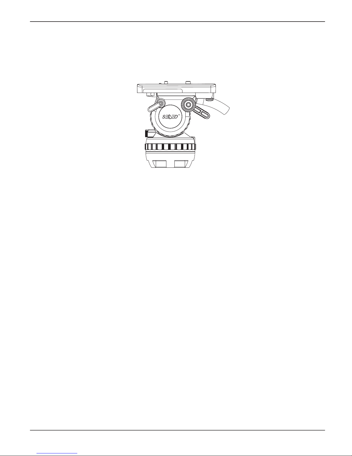
SC-Video 10/100VP (Left-Hand Side)
Fig 1
(1) Slide plate clamp
(2) Tilt drag adjustment knob
(3) Pan drag adjusment knob
(4) Bowl clamp
(5) Pan bar mounting
(6) Tilt brake knob
(7) Pan brake knob
(8) Head bowl
(1)
(6)
(5)
(3)
(4)
(2)
(7)
(8)

5
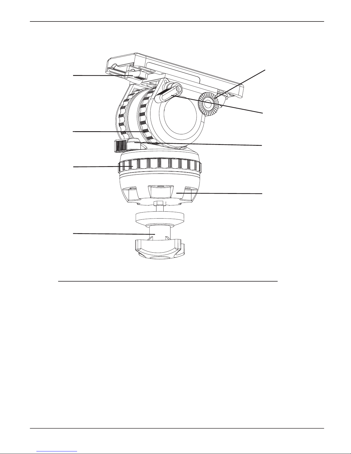
SC-Video 10/100VP (Right-Hand Side)
Fig 2
(9) Quick release knob
(10) Balance knob
(11) Level bubble
(12) Quicklock wedge
(13) Pan bar clamping sleeve
(14) Pan bar clamping lever
(9)
(10)
(11)
(12)
(13)
(14)

6
Operation
Installing the head on a tripod
The Ares 3 fluid head is supplied with an integral 100mm ball mount, designed for installation
on a compatible Secnovo tripod.
To install the head, remove the bowl clamp (4) from the head (turn bowl clamp anti-clockwise
as in Figure 3), position the head on the tripod and refit the bowl clamp from below. Level the
head with aid of level bubble (11) and apply the bowl clamp (turn bowl clamp clockwise as
in Figure 3).
Fig 3
Installing the head on a tripod
Ares 3 head (SC-Video 10/100VP)
Ares 3 tripod (SC-EN/CF 100M)
(4)
Loosen the bowl clamp (Anti-clockwise)
Tighten the bowl clamp (Clockwise)
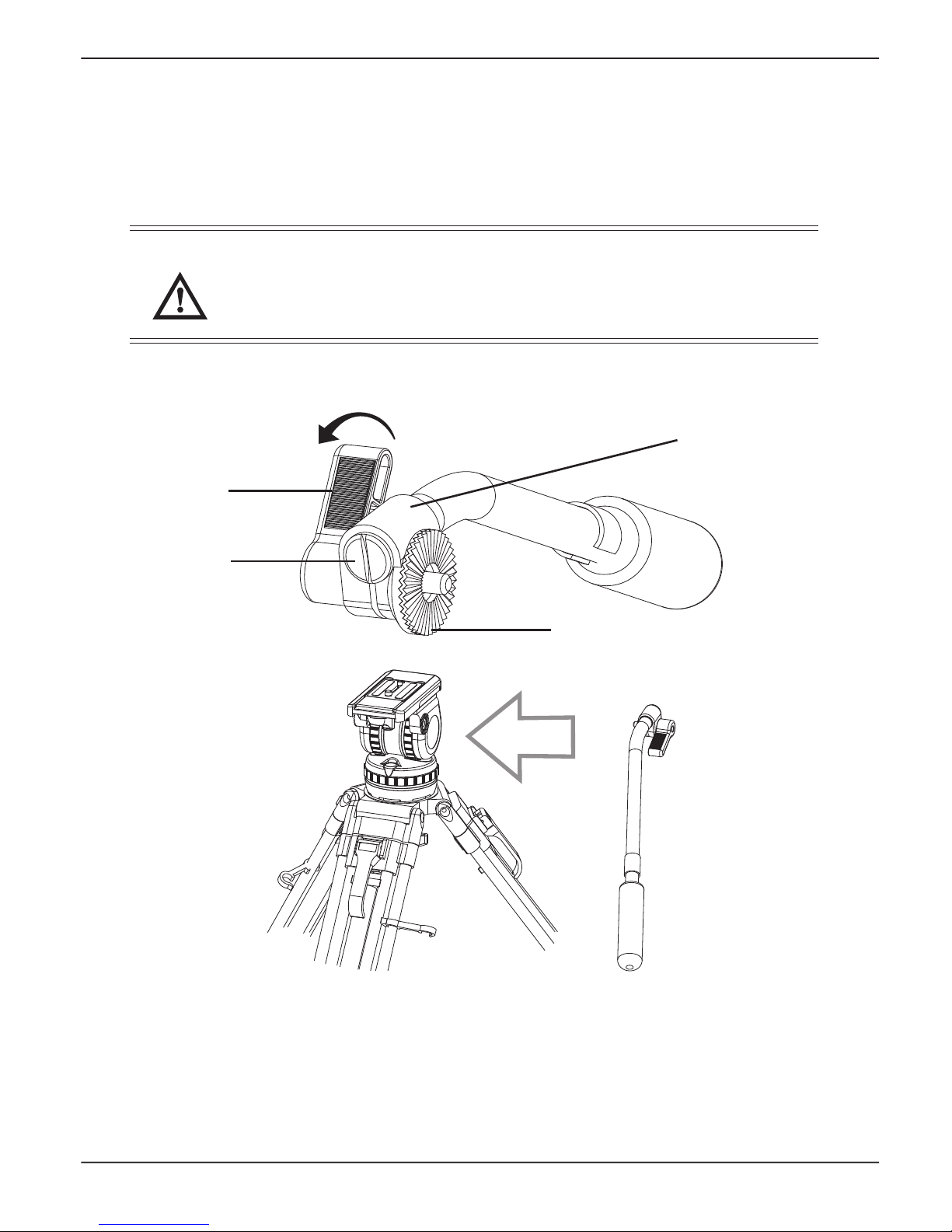
Opening the pan bar
Open the black clamping lever (14) of the pan bar and move the pan bar into the desired position.
Apply the clamping lever of the pan bar. During transportation the pan bar can be moved next to
the tripod legs.
WARNING! Open the clamping lever of the pan bar far enough. The teeth of the pan bar
clamp should not clatter while moving the pan bar. However, a plastic protector,
clamping washer (15) prevents against wear of metal toothed ring. Make sure that
the teeth interleave with each other when closing the clamping lever of the pan bar.
Fig 4
Installing the pan bar on a head
7
(16)
(15)
(14)
(13)
Tighten the clamping lever (Clockwise)

Fig 5
Use of the enclosed pan bar on the left side of the fluid head is also possible. For this, it is
advisable to relocate the clamp on the pan bar. The pan bar has to be removed from the head
and the black plastic cap (16) on its top should be opened and removed with a coin or screwdriver.
The toothed clamping sleeve (13) should be removed and relocated as in Figure 5. The plastic
screwed cap need to be tightened again.
(16)
(13)
Left-handed pan bar
8

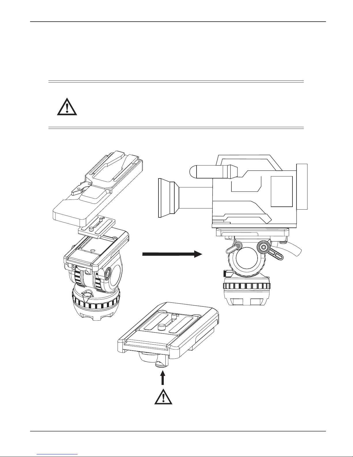
Tighten the tilt brake before mounting the camera
Free the Quicklock wedge (12) from slide plate (17) by pulling the locking button down (9.2)
and then operating the wedge-releasing lever (9.1) to another end.
Fit the wedge either to the camera or the camera adaptor with two screws provided. If using
the camera adaptor, just mount the camera on the camera adaptor after the wedge is attached
with the camera adaptor.
Mounting the camera
Fig 6
9
Pulling down (9.2)
Turning (9.2)
(9.1)
(9.2)
(12)
(17)
10
Insert the wedge into the camera plate until an audible click indicates that the Quicklock wedge
is locked in position.
WARNING! When mounting the camera/placing the wedge, make sure not to hold fingers
within the range of the locking lever (9.1) and camera plate receptacle, since the
lever may snap back.
When the camera is mounted, the bowl clamp must only be released if camera
and tripod are secured against falling away.
Fig 7
WARNING! No finger allowed here

Balancing the head
Balancing the head achieves two objectives. Firstly, when the head is correctly balanced the
operator will need a minimum amount of effort to move the head. Secondly, once balanced,
the head and its payload can be set to any tilt position and the head will maintain this position
with ‘hand off’.
Prior to balancing the head ensure that the pan bars and ancillary equipment have been fitted
in order to prevent upsetting the balance once it has been achieved.
WARNING! Be prepared to prevent the head falling away suddenly.
I. Release the tilt brake knob (6).
II. Turn the balance knob to position 0 and keep holding the camera.
III. Turn the tilt drag to position 0.
IV. Hold the camera in the horizontal position by securing the pan bar. Release
the slide plate clamp (1) and slide the camera backwards or forward until it
balances horizontally. Tighten the slide plate clamp.
V. Turn the balance knob to the number which best compensates for the weight of
the camera, i.e. for as little movement upward or downword in any position.
VI. Select the tilt drag level by turning the tilt drag adjustment knob (2). In the correctly chosen
position the camera should not perform any tilt movement.
Fig 8
I II
11
Release the tilt brake knob
Position 0
0
1
2

12
Fig 8 continued
III.
IV
V
VI
0
1
2
Position 0
1
2
3
4
0
1
2
3
Release slide plate clamp
Tighten slide plate clamp

Friction brakes (6,7) on each axis allow the head to be locked at any chosen position.
To apply the brake, turn the lever fully clockwise. To release the brake, turn the lever
counter-clockwise.
Pan and tilt brakes
WARNING! When the brakes are not in use, make sure the brakes is at the released status.
DO NOT use the brakes to supplement drag.
Both drag knobs (2,3) are provided with graduated scales.
By turning the vertical setting and the horizontal setting, selects the desired drag level.
Make sure that you always turn the setting to the next indexed position (arrow). Engage the
retainer pins by slowly panning or tilting the camera.
Pan and tilt drag
NOTE: Panning or tilting the camera with settings between the indexed positions can damage
the retainer pins and/or disks. Reduce drag to a minimum when the head is out of use
for long periods.
Release the tilt or
pan brakes
Tighten the tilt or pan brakes
Increase pan
or tilt drag
13
Fig 9

Servicing
14
Fig 10
Routine maintenance
During use, check the following
Check the condition of the clamping washer (15) and the pan bar clamping sleeve (13),
replace them if the teeth of the clamping washer and clamping sleeve are almost weared away.
Check the effectiveness of the slide plate, add some grease lubricant onto the slide plate if
slide plate do not move when tilting to +45° and -45° (as shown in Figure 10).
Check the effectiveness of the pan and tilt drag controls. Repair as necessary.
Check the effectiveness of the pan and tilt brake knob. Repair as necessary.
No further routine maintenance is required.
Cleaning
During indoor use the only cleaning required should be a regular wipe over with a lint-free cloth.
Dirt accumulated during storage may be removed using a semi-stiff brush. Particular attention
should be given to the leveling bowl and mounting face of the head.
Use out-of-doors under adverse condition will require special attention. Salt spray should be
washed off with fresh water at the earliest opportunity. Sand and dirt acts as an abrasive and
should be removed using a semi-stiff or vacuum cleaner.
NOTE: Use only detergent-based cleaners. DO NOT use solvent- or oil-based cleaners,
abrasives or wire brushers to remove accumulations of dirt, as these damage
the protective surfaces.
Tripod
Contents
Operation …………………………………………… Page 17
Servicing ……………………………………………… Page 19
Cleaning ………………………………………………………………… Page 19
Routine maintenance ……………………………………………………… Page 19
Adjusting the leg clamps …………………………………………………… Page 19
15
SC-ENG/CF 100M

16
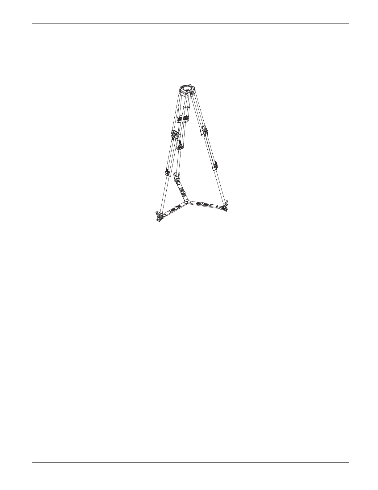
SC-ENG/CF 100M Tripod
Fig 11
(18) Tripod bowl
(19) Top clamp assembly
(20) Bottom clamp assembly
(21) Floor spreader
(22) Locking clip
(23) Mid-level spreader attachment assembly
(24) Clamping knob
(18)
(19)
(22)
(23)
(24)
(20)
(21)

Operation
Lift the complete tripod and head out of the case and keep the floor spreader (21) attached
to the tripod.
Release the three locking clips (22), open out the legs while holding the legs. Gentle foot or hand
pressure on the spreader will ensure that the legs are fully spread.
NOTE: Always use the spreader where possible as this increases rigidity of the tripod.
Being flexible, the spreader compensates for uneven ground. It can be removed
and a dolly fitted. At the fullest extension of the spreader and with all legs fully
retracted, the tripod can be used at its lowest operating height. Although the tripod
can be set up lower than this without the spreader, it is NOT recommended as
the tripod geometry becomes unstable.
(22)
Release the locking clips
Spread the legs
Fig 12
17

Adjust the operating height by undoing the leg clamps (19.1, 20.1) and pulling the tripod up to the
desired height. Adjust the spreader if necessary. Level the head with aid of the level bubble.
Apply the clamps (19.1, 20.1) to lock the tripod.
Pull up
(19.1)
Lift up to release
Press down to lock
(20.1)
Lift up to release
Press down to lock
18
Fig 13
This manual suits for next models
1
Table of contents
Other Secced Camera Accessories manuals


