DUCTING GUIDELINES, OUTLET CHART, RETURN AIR GRILLE SIZING & ZONING
33
GOOD DUCTING GUIDLINES
Correct ductwork installation is critical to ensure correct operation of the heating system, and
to prevent premature failure of the fan and/or heat exchanger. The following must be
considered:
SUPPLY AND RETURN AIR DUCTING
zDuctwork should be adequately sized to suit the heater and installation to prevent
excessive system back pressure.
zDuct run > 6m - increase the full length of the duct run and spigot diameter by 50mm.
zDuct run > 9m - increase the full length of the duct run and spigot diameter by 100mm.
zDuctwork should be adequately supported and free from air leaks.
zVolume dampers are recommended to enable proper balancing of the system.
zBends in ducting must be as smooth as possible to minimise restriction to air flow,
recommended MINIMUM bend radii are: - 150 to 300 mm duct 1.5 duct diameters
- 350 to 400 mm duct 2 duct diameters
zThe minimum RETURN AIR DUCT length should be 3m, and should include a bend to
help reduce noise transmission along the duct.
OUTLET REGISTERS
zAt least one outlet register must be provided in all areas to be heated.
zCare should be taken to prevent cold spots, due to excessive draught or insufficient
outlets.
zThe normal position of furniture in the home must be considered when locating registers.
zThe type of register should be selected to suit the application:
- Registers installed in the floor should discharge sideways.
- Registers installed in the ceiling should discharge predominantly vertically.
RETURN AIR GRILLE LOCATION
zAlways locate the return air grille in a suitably heated area, central hallways are usually
the most suitable.
zDo not locate in a bathroom or laundry as the moisture present in these rooms may settle
on the fan when not in use.
zThe return air grille should be located so that it is unobstructed by carpets, clothing,
furniture.
zAir should not be drawn through areas that are not heated.
zIt is recommended that the return air grille is located at a low level - system performance
may be reduced if a high level return air grille is used. N.B Not Recomended above 2.7m.
zIn a zoned system, the return air grille must be located in the "common" zone, ie, in a
zone that cannot be turned off.
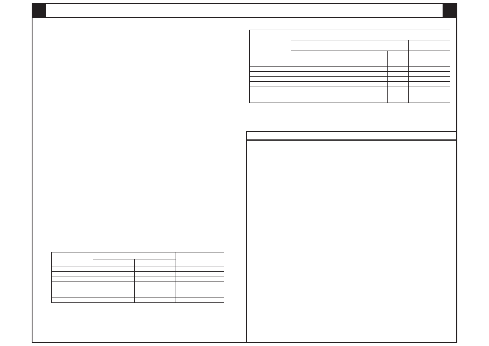
500 x 40015/16/20/23 750 x 400 300
No filter With filter
Minimum grille dimensions (mm) Duct connection
diameter (mm)
Model (kW)
TH3-TH4-TH5
750 x 40030/32 1000 x 400 350
900 x 40035 1200 x 400 400
600 x 40020X/23X 900 x 400 350
750 x 40025X 1000 x 400 350
900 x 40030X/32X 1200 x 400 400
RETURN AIR GRILLE SIZING
zEquivalent grille sizes may be used.
zFitting a filter is recommended.
zA filter may generate some air flow noise - the owner should be advised.
zThe owner should be advised to clean the filter every 2 weeks and replace annually.
1. Based on standard 100 x 300mm floor outlets and 150mm round ceiling outlets.
2. Minimum outlets open to achieve optimum turndown performance.
3. Recommended installed outlets based on maximum fan speed set to 10 - refer Technical & Training
Manual "System Installation Options" for outlet numbers with lower maximum fan speed settings.
4. 'X' in model refers to extra-air models - maximum outlets will be reduced when a cooling coil is installed.
415/16 1 5 2 5-8 5-8 6-11 6-11
5
20/23 2 6 3 6-11 6-11 8-14 8-14
5
20X/23X [4] 2 7 3 7-12 7-12 9-15 9-15
7
30/32 3 10 4 10-16 10-16 13-21 13-21
8
30X/32X [4] 3 11 4 11-18 11-18 14-23 14-23
NA
35 (TH4 only) 3 NA 4 NA 11-18 NA 14-23
TH3 TH4/TH5 TH3 TH4/TH5 TH3 TH4/TH5 TH3 TH4/TH5
Ceiling Underfloor Ceiling Underfloor
Minimum outlets open [2] Recommended installed outlets [3]
Model (kW)
6
25 (TH3/4 only) 2 8 3 8-13 8-13 10-17 10-17
5
25X (TH3/4 only [4])2 8 3 8-14 8-14 11-18 11-18
OUTLET CHART [1]
TH4 and TG5 model heaters can be installed and set-up to independently heat different areas
within the home, either from a single Spectrolink Comfort Control (SCC) or from up to four
independent SCC's. In each case zone dampers must be installed into selected duct runs to
allow the air flow to a zone/s to be turned on or off.
1 SCC Thermostat:
Each zone is controlled independently from a single SCC. The SCC must be located in a
"common zone", ie, a zone that cannot be turned off, and that includes the return air.
Multiple SCC thermostats:
Each zone is controlled independently from its own SCC - this allows zones to be set at
different temperatures, and to be controlled from within the zone. Each zone that has its own
SCC thermostat must include a zone damper.
ZONING - TH4 & TH5
HINTS FOR ZONED SYSTEMS
zTalk to the customer to get an understanding of their requirements.
zAllow for an outlet near the return air to prevent drafts and cold spots.
zFor 1-SCC systems ensure that the COMMON zone is always heated, even if it is only a
small air flow. The common zone must include a return air grille.
zExplain to the customer the function of the return air duct, and the need for a clear air
path to the return air grille - air cannot travel through closed doors.
zFor 1-SCC systems position the wall control in the COMMON zone.
zDO NOT in any way obstruct the flow of return air.
ZONE FAN SPEEDS
zZone fan speeds must be set to ensure an appropriate air flow for each zone. If the fan
speed is set too high for the number of outlets this may cause high air flow noise and will
not be covered under warranty.
KITS AND PARTS REQUIRED FOR ZONING
z24V zone kit P/No 077215 - to suit 24Vac zone dampers:
Kit includes - zone connection PCB, communication loom, 24Vac transformer.
z240V zone kit P/No 077208 - to suit 240Vac zone dampers:
Kit includes - zone connection PCB, communication loom, PCB connection wires.
zMultiple SCC's - one SCC is supplied with each 4 & 5 star installation accessories kit -
an additional SCC & loom is required for each additional zone
- SCC/loom kit P/No 076010.
zZone dampers and suitable wiring (not supplied by Seeley International).
25 600 x 400 900 x 400 350