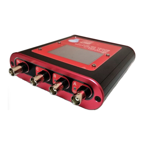
SEFRAM 4451 User manual

SEFRAM 4451
50 MHz PROGRAMMABLE
PULSE GENERATOR
OPERATING MANUAL

Operating Manual SEFRAM 4451
M4451 A00 2

Operating Manual SEFRAM 4451
M4451 A00 3
INDEX
Page
SAFETY SUMMARY
Section 1 General Information 5
1.1 Introduction 8
1.2 Description 8
1.3 Safety Remarks 8
1.4 Specifications 9
Section 2 Installation
2.1 Introduction 14
2.3 Initial Electrical Inspection 14
2.4 Instrument Mounting 14
2.5 Power Requirements 14
2.6 Grounding Requirements 15
2.7 Signal Connections 15
2.8 GPIB Connections 18
Section 3 Operating Instructions
3.1 Introduction 21
3.6 Menu Keys 23
3.10 Power-On Settings 30
3.12 Pulse Definitions 32
3.13 Parameter Limitations 33
Section 4 Programming
4.1 Overview 35
4.2 Device State 35
4.3 Interface Function Subsets 35
4.4 Device Address 36
4.5 Message Exchange Protocol 36
4.6 Instrument Identification 36
4.7 Instrument Reset 37
4.9 Command Syntax 37
4.10 Status Reporting 39
4.11 IEEE488.2 Common Commands 42
4.12 Instrument Control Commands 45
4.13 IEEE488.1 Interface Messages 60
4.14 SCPI Command Tree 61

Operating Manual SEFRAM 4451
M4451 A00 4
Section 5 Performance Check Procedure 66
5.1 Introduction 67
5.2 Test Equipment 67
5.3 Electrical Checkout 67
5.4 Performance Tests 68
Declaration of conformity 71

Operating Manual SEFRAM 4451
M4451 A00 5
Safety Summary
The following safety precautions apply to both operating and maintenance personnel and must
be observed during all phases of operation, service, and repair of this instrument. Before
applying power, follow the installation instructions and become familiar with the operating
instructions for this instrument.
Failure to comply with these precautions or with specific warnings elsewhere in this manual
violates safety standards of design, manufacture, and intended use of the instrument. SEFRAM
assumes no liability for a customer’s failure to comply with these requirements. This is a Safety
Class I instrument.
GROUND THE INSTRUMENT
To minimize shock hazard, the instrument chassis and cabinet must be connected to an
electrical ground. This instrument is grounded through the ground conductor of the supplied,
three-conductor ac power cable. The power cable must be plugged into an approved three-
conductor electrical outlet. Do not alter the ground connection. Without the protective ground
connection, all accessible conductive parts (including control knobs) can render an electric
shock. The power jack and mating plug of the power cable meet IEC safety standards.
DO NOT OPERATE IN AN EXPLOSIVE ATMOSPHERE
Do not operate the instrument in the presence of flammable gases or fumes. Operation of
any electrical instrument in such an environment constitutes a definite safety hazard.
KEEP AWAY FROM LIVE CIRCUITS
Instrument covers must not be removed by operating personnel. Component replacement and
internal adjustments must be made by qualified maintenance personnel. Disconnect the power
cord before removing the instrument covers and replacing components. Under certain
conditions, even with the power cable removed, dangerous voltages may exist. To avoid
injuries, always disconnect power and discharge circuits before touching them.
DO NOT SERVICE OR ADJUST ALONE
Do not attempt any internal service or adjustment unless another person, capable of rendering
first aid and resuscitation, is present.
DO NOT SUBSTITUTE PARTS OR MODIFY THE INSTRUMENT
Do not install substitute parts or perform any unauthorized modifications to this instrument.
Return the instrument to SEFRAM or any certified center for service and repair to ensure that
safety features are maintained.
WARNINGS AND CAUTIONS
WARNING and CAUTION statements, such as the following examples, denote a hazard and
appear throughout this manual. Follow all instructions contained in these statements.
A WARNING statement calls attention to an operating procedure, practice, or condition, which,
if not followed correctly, could result in injury or death to personnel.
A CAUTION statement calls attention to an operating procedure, practice, or condition, which,
if not followed correctly, could result in damage to or destruction of part or all of the product.
WARNING:
Do not alter the ground connection. Without the protective ground
connection, all accessible conductive parts (including control knobs) can
render an electric shock. The power jack and mating plug of the power cable
meet IEC safety standards.

Operating Manual SEFRAM 4451
M4451 A00 6
WARNING:
To avoid electrical shock hazard, disconnect power cord before removing
covers. Refer servicing to qualified personnel.
CAUTION:
Before connecting the line cord to the AC mains, check the rear panel AC line
voltage indicator. Applying a line voltage other than the indicated voltage
can destroy the AC line fuses. For continued fire protection, replace fuses
only with those of the specified voltage and current ratings.
CAUTION:
This product uses components that can be damaged by electrostatic
discharge (ESD). To avoid damage, be sure to follow proper procedures for
handling, storing and transporting parts and subassemblies that contain
ESD-sensitive components.

Operating Manual SEFRAM 4451
M4451 A00 7

Section 1
General Information
1.1 Introduction
This manual contains information required to operate, program, check and maintain the SEFRAM 4451 - 50
MHz PROGRAMMABLE PULSE GENERATOR.
1.2 Description
The SEFRAM 4451 is a high performance programmable pulse generator. The instrument generates pulses
with a repetition rate to 50MHz, width from 10ns, variable delay, variable transition times and amplitude.
The pulses can be output in continuous, triggered, gated or burst mode with an internal or external trigger
signal.
The SEFRAM 4451 can be remotely operated via the RS-232 or the IEEE488 interface bus and is SCPI
compatible.
1.3 Safety Remarks
The SEFRAM 4451 is a SAFETY CLASS 1 instrument. Before operation, review the SAFETY SUMMARY
at the front of this manual.

Operating Manual SEFRAM 4451
M4451 A00 9
1.4 SPECIFICATIONS
The following specifications describe the instrument performance after a 20 minute warm-up period into a 50 ohms
load. All timing characteristics are measured at 50% of amplitude with fastest edges.
PULSE FUNCTIONS
Single - One pulse at each selected period up to 50MHz repetition
rate.
Double - One pair of pulses at each period up to 25MHz repetition rate.
Both pulses have the same selected width; the position of the second pulse
set by the delay control.
OPERATING MODES
Continuous - Output continuous at programmed period rate.
Triggered - Output quiescent until triggered by an internal, external, GPIB or manual
trigger, then generates one cycle at programmed period rate.
Gated - Same as triggered mode except pulses are output for the duration of the gated
signal. The last cycle started is completed.
Burst - Same as triggered mode for programmed number of cycles from 2 to 999,999
as set by the N-BURST function.
External Width - Trigger duration and rate sets pulse width and repetition.
TIMING CHARACTERISTICS
PERIOD
Range - 20 ns to 10 s (50MHz to 0.1Hz repetition rate).
Resolution - Up to 6 digits, limited to 100 ps.
Accuracy - ±0.01 %
Jitter - < 0.01% of setting +20ps on Period, Width and Delay.
WIDTH

Operating Manual SEFRAM 4451
M4451 A00 10
Range - 10ns to (Period - 10ns off time).
Resolution - Up to 6 digits, limited to 100 ps.
Accuracy - ±(0.5% of setting +500 ps)
Double Pulse: - ±(0.5% of setting +3 ns) for the second pulse.
DELAY
Range - 0ns to (Period – Width - 10ns off time).
Resolution - Up to 6 digits, limited to 100 ps.
Accuracy - ±(0.5% of setting +500 ps)
DUTY CYCLE
Range -1 to 99%.
Resolution -3 digits (0.1%).
Accuracy: -Limited by width and pulse accuracy.
OUTPUT CHARACTERISTICS
AMPLITUDE
High Level Range - -9.90V to +10V into 50 ohms load (-19.80V to +20V into open circuit).
Low Level Range - -10V to +9.90V into 50 ohms load (-20V to +19.80V into open circuit).
Amplitude Range - 0.1V to 10V p-p into 50 ohms load (20V p-p max into open circuit).
Resolution - 3 digits limited to 10mV.
Accuracy - ±1% of setting ±10 mV into 50 ohms.
Aberrations - <5% + 20mV into 50 ohms load, for pulse levels between ±5V.
Output Resistance - 50 ohms
Offset Accuracy: - ±1% ±25 mV.
TRANSITION TIMES
Range - <6ns to 10ms variable. Leading and trailing edges settable separately and
limited to 20:1 ratio between settings into one of the following ranges: 5ns-

Operating Manual SEFRAM 4451
M4451 A00 11
100ns; 50ns-1.0us; 500ns-10us; 5.0us-100us; 50us-1.0ms; 500us-10ms, 5 ms –
100 ms.
Resolution - 3 digits limited to 10 ps.
Accuracy - ±(5% of setting +2ns)
Linearity - <5% deviation from a straight line between 10% and 90% points,
for transitions > 50 ns.
INTERNAL TRIGGER
Range - 100ns to 100s.
Resolution - 4 digits limited to 100ns.
Accuracy - ±0.01%
INPUT AND OUTPUT
TRIGGER INPUT
Sensitivity - 200 mVp-p minimum.
Minimum Width - 10ns.
Maximum Rate - 50MHz.
Input Impedance - 10 KMΩ
Input Protection - +15V DC plus peak AC.
Range - Selectable from -10V to +10V.
Resolution - 3 digits limited to 10mV.
Slope Selection - Positive or Negative.
SYNC OUTPUT
A TTL level pulse at the programmed period. Output impedance is 50 ohms, protected against short circuit
and up to ±15V accidental input. The high level is >2V into 50 ohms and with 3.5ns typical transition
times.

Operating Manual SEFRAM 4451
M4451 A00 12
GPIB PROGRAMMING
Internal - IEEE-488.2 and SCPI compatible.
Address - 0-30 front panel selected.
Subsets - SH1, AH1, T6, L4, SR1, RL1, PP0, DC1,DT1, C0, E2.
GENERAL
Memory -Non volatile, stores up to 99 complete panel settings. Last user setup also
retained at power down.
Power Requirements - 100-240V, ±10%, 48-66 Hz, 50VA maximum.
Dimensions - Height 8.8cm, Width 21.3 cm, Length 30 cm
Weight - Aprox 3kg Net.
EMC - According to EN55011 class B for radiated and conducted emissions.
Electrical Discharge Immunity - According to EN55082
Safety Specifications - According to EN61010
Operating Temperature - 0°C to +50°C.
Storage Temperature - -20°C to +60°C.
Humidity - 90% RH at 0°C to 30°C,
CE Labeled
NOTES
Specifications are verified according to the Performance Check Procedure in this manual.
Specifications not qualified in this manual are either explanatory notes or general performance
characteristics only.

Operating Manual SEFRAM 4451
M4451 A00 13

Operating Manual SEFRAM 4451
M4451 A00 14
Section 2
Installation
2.1 Introduction
This section contains installation information, power requirements, initial inspection and signal connections
for the SEFRAM 4451.
2.2 Initial Mechanical Inspection
Upon receipt, inspect the instrument for any damage that might have occurred in transit and verify the
contents of the shipment (accessories and installed options).
2.3 Initial Electrical Inspection
The SEFRAM 4451 is calibrated and ready for use when received. The Electrical Performance Check
Procedure is detailed in Section 5.
2.4 Instrument Mounting
The SEFRAM 4451- 50 MHz PROGRAMMABLE PULSE GENERATOR is intended for bench use. The
instrument includes a front feet tilt mechanism for optimum panel viewing angle. The instrument does not
require special cooling when operated within conventional temperature limits.
A 5 cm minimum clearance must be provided at the rear of the unit for proper convection cooling. The unit
can be installed in a closed rack or test station if proper airflow is assured.
2.5 Power Requirements
The SEFRAM 4451 can be operated from any source of 100-240V +/-10% AC, at a frequency from 48Hz to
66Hz. The maximum power consumption is 50 VA.

Operating Manual SEFRAM 4451
M4451 A00 15
2.6 Grounding Requirements
To minimize shock hazard, the instrument chassis and cabinet must be connected to an electrical ground. This
instrument is grounded through the ground conductor of the supplied, three-conductor ac power cable. The
power cable must be plugged into an approved three-conductor electrical outlet.
WARNING:
Do not alter the ground connection. Without the protective ground connection, all
accessible conductive parts (including control knobs) can render an electric
shock. The power jack and mating plug of the power cable meet IEC safety
standards.
2.7 Signal Connections
The BNC connectors are:
OUTPUT - Up to 10V peak-to-peak into 50 ohm impedance (20V p-p into open circuit). The instrument
is protected from short circuit to ground.
TRIG IN - 10 KΩimpedance, selectable positive or negative slope, variable level from -10V to +10V.
Input protected to ±15V.
SYNC OUT - A positive pulse signal in phase with the main output. TTL levels with a 50 ohm source
impedance and with 3.5ns typical transition times.
2.7.1 Maintaining Pulse Fidelity
Due to the extremely fast pulse rise times obtained from the instrument, special consideration must be given
to preservation of pulse fidelity. Even at low repetition rates, high frequency components are present in the
output waveform. Use high quality coaxial cables, attenuators and terminations.
RG 58 type coaxial cable and typical BNC connectors exhibit impedance tolerances which may cause visible
reflections. For maximum fidelity, use short, high quality, 50 ohm coaxial cables.
When signal comparison measurements or time difference determinations are made, the two signals from the
test device should travel through coaxial cables with identical loss and time delay characteristics.
When making connections that are not in a 50 ohm environment, keep all lead lengths short, 1/4 inch or less.

Operating Manual SEFRAM 4451
M4451 A00 16
2.7.2 Impedance Matching
A mismatch, or different impedance in a transmission line, generates a reflection back along the line to the
source. The amplitude and polarity of the reflection are determined by the load impedance in relation to the
characteristic impedance of the cable. If the load impedance is higher than the characteristic impedance of
the line, the reflection will be of the same polarity as the applied signal. If it is lower, the reflection will be of
opposite polarity. These reflections add or subtract from the amplitude of the incident pulse causing
distortion and irregular pulse shapes.
Impedance-matching network that provides minimum attenuation
A simple resistive minimum attenuation impedance matching network that can be used to match the
instrument output into relatively low impedance is shown in the above figure. To match impedance with the
illustrated network, the following conditions must exist:
and
Therefore:
R1 R2 = Z1 Z2, and R1 Z1 = R2 (Z2-Z1)
or
and
()
R
Z
R
R
Z
R
Z
122
1221
+
++
=
RZZZ1221=−()
RZ Z
ZZ
21 2
21
=
−
RRZR
ZR
1112
12
++
+

Operating Manual SEFRAM 4451
M4451 A00 17
For example: to match a 50Ωsystem to a 125Ωsystem, Z1 equals 50Ωand Z2 equals 125Ω
Therefore:
Ω
and
Ω
Although the illustrated network provides minimum attenuation, for a purely resistive impedance-matching
device, the attenuation as seen from one end does not equal that seen from the other end. A signal (E1)
applied from the lower impedance source, encounters a voltage attenuation (A1) which is greater than 1 and
less than 2, as follows:
A signal (E2) applied from the higher impedance source (Z2) encounters a greater voltage attenuation (A2),
which is greater than 1 and less than 2 (Z2/Z1):
In the example of matching 50Ωto 125Ω,
and
The illustrated network can be modified to provide different attenuation ratios by adding another resistor
(less than R1) between Z1 and the junction of R1 and R2.
When constructing such a device, the environment surrounding the components should also be designed to
provide smooth transition between the impedances. Acceptable performance can be obtained with discrete
components using short lead lengths; however, a full coaxial environment is preferred.
The characteristic impedance of a coaxial device is determined by the ratio between the outside diameter of
the inner conductor to the inside diameter of the outer conductor expressed as:
2.7.3 Rise time Measurements in Linear Systems
Consider the rise time and fall time of associated equipment when measuring the rise time or fall time of a
linear device. If the rise time of the device under test is at least ten times slower than the combined rise times
of the instrument, the monitoring oscilloscope, and associated cables, the error introduced will not exceed
1%, and usually may be ignored. If the rise time or fall time of the test device is less than ten times slower
R1 125 125 50 96 8=−=().
R250 125
125 50 64 6=
−
=.
AE
ER
Z
11
2
1
21==+
AE
ER
RR
Z
22
1
1
2
1
11==++
A196 8
125 1177=+=
..
A296 8
64 6
96 8
50 1443=++=
.
.
..
ZD
d
0138 10=
ε
log

Operating Manual SEFRAM 4451
M4451 A00 18
than the combined rise times of the testing system, determine the actual rise time of the device under test by
using the following formula:
Rt equals the overall rise time or fall time of the entire measurement system and R1, R2, R3, etc. are the rise
times or fall times of the individual components in the system.
2.8 GPIB Connections
The rear panel GPIB connector is a AMPHENOL 57-10240 or equivalent, and connects to a standard IEEE-
488 bus cable connector. The GPIB line screens are not isolated from chassis and signal ground.
The instrument is shipped with the address set to decimal 10. The address can be changed from the front
panel by using the "SPCL" menu, refer to "SPECIAL FUNCTIONS".
GPIB connector
2.9 RS-232 Connection
The rear panel RS-232 connector is a standard DB-9 male connector configured as a
DCE:
Rt Rt Rt Rt=+++( ) ( ) ( ) ......122232

Operating Manual SEFRAM 4451
M4451 A00 19
DB-9 pin Name Note Computer DB25
pin Direction
1
2
3
4
5
6
7
8
9
N/C
RXD
TXD
N/C
GND
N/C
RTS
CRS
N/C
-
Receive Data
Transmit Data
-
Signal ground
-
Request to Send
Clear to send
-
8
3
2
-
7
6
4
5
-
In
In
Out
Out
-
In
Out
In
-
2.10 RS-232 Configuration
Before connecting the RS-232 interface, the instrument must be properly configured.
Select UTILITY menu and then F4 - RS232 for setting of the desired baud date.
The instrument use 8 data bits, 1 stop bit, no parity and baud rate from 1200 to 115K
(1200, 2400, 4800, 9600, 19200, 38400, 57600 and 115000).

Operating Manual SEFRAM 4451
M4451 A00 20
Table of contents
