SPECIFICATIONS
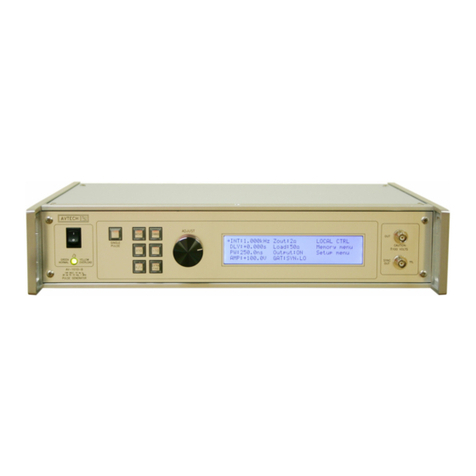
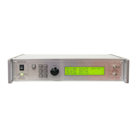
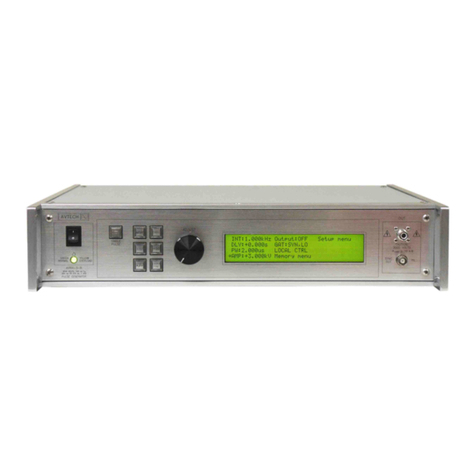
Model: AVR-G1-B1
A plitude: 10 to 250 Volts
Basic wavefor : Nor al pulse
Pulse width (FWHM): 100 ns to 1 s2
Load i pedance: ≥ 10 kΩ
Output i pedance6: 50 Ω
Rise, fall ti es (20%-80%)7: ≤ 20 ns
PRF: 1 Hz - 10 kHz
Maxi u duty cycle: 80 %
Polarity3: Positive or negative or both (specify)
GPIB and RS-232 control1: Standard on -B units.
LabView Drivers: Check http://www.avtechpulse.co /labview for availability and downloads
Ethernet port, for re ote
control using VXI-11.3, ssh,
telnet, web:
Included. Reco ended as a odern alternative to GPIB / RS-232.
See http://www.avtechpulse.co /options/vxi for details.
Settings resolution: The resolution of the ti ing para eters (pulse width, delay, period) varies, but is always better than
0.15% of (|set value| + 20 ns). The a plitude resolution is < 0.1% of the axi u a plitude.
Settings accuracy: Typically ± 3% (plus ±1V or ± 2 ns) after 10 inute war up. For high-accuracy applications
requiring traceable calibration, verify the output para eters with a calibrated oscilloscope8.
Burst ode: Optional4. Generates 1-500 pulses per trigger event. See http://www.avtechpulse.co /options/br.
Propagation delay: ≤ 100 ns (Ext trig in to pulse out)
Jitter: ± 100 ps ± 0.03% of sync delay (Ext trig in to pulse out)
DC offset: Option available5
Trigger odes: Internal trigger, external trigger (TTL level pulse, > 10 ns, 1 kΩ input i pedance), front-panel
“Single Pulse” pushbutton, or single pulse trigger via co puter co and. In the external trigger
ode, the pulse width ay be set by the instru ent, or it ay be set to track the input pulse width.
Variable delay: Sync to ain out: 0 to 1.0 seconds, for all trigger odes (including external trigger).
Sync output: > +3 Volts, > 50 ns, will drive 50 Oh loads
Gate input: Synchronous or asynchronous, active high or low, switchable. Suppresses triggering when active.
Connectors: Out, Trig, Sync, Gate: BNC
Power require ents: 100 - 240 Volts, 50 - 60 Hz
Di ensions (H x W x D): 100 x 430 x 375 (3.9” x 17” x 14.8”)
Chassis aterial: Alu inu fra e and handles, gray vinyl on alu inu cover plates
Rack- ount kit: Optional. Add -R5 to the odel nu ber.
Te perature range: +5°C to +40°C
1) -B suffix indicates IEEE-488.2 GPIB and RS-232 control of a plitude, pulse width or duty cycle (as appropriate), pulse repetition frequency, and
delay (See http://www.avtechpulse.co /gpib).
2) When triggered externally, the pulse width can be set by the pulse instru ent controls, or it ay be set to track the input trigger pulse width.
3) Indicate desired polarity by suffixing odel nu ber with -P or -N (i.e. positive or negative) or -PN for dual polarity option.
4) Add the suffix -BR to the odel nu ber to specify the burst ode option. See http://www.avtechpulse.co /options/br for details about this option. Not
available on the AVR-G5-B odel.
5) To generate a 0 to ±50V offset internally, add the suffix -OT to the odel nu ber. When generating a pulse with positive a plitude, the offset plus
a plitude ust re ain between 0 and +250V, and when generating a pulse with negative a plitude, the offset plus a plitude ust re ain between
0 and -250V.
6) This is the resistance in series with the output, internally. The 50 Oh series resistance provides trans ission line back- atching to absorb
reflections fro the load. This is not the sa e as the load i pedance. The AVR-G series can not drive 50 Oh loads.
7) For a non-capacitive load. The 50 Oh output i pedance will cause rise and fall ti e degradation if the load has capacitance, governed by the RC
ti e constant.
8) These instru ents are provided with a basic calibration checksheet, showing a selection of easured output para eters. These easure ents are
perfor ed with equip ent that is calibrated on a regular basis by a third-party ISO/IEC 17025:2005 accredited calibration laboratory. However,
Avtech itself does not clai any accreditation. For applications requiring traceable perfor ance, use a calibrated easure ent syste rather than
relying on the accuracy of the pulse generator settings.

