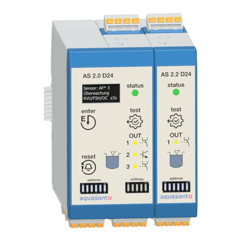
Selectron XT543-N User manual

t2t1t2
NO
Contact
Supply
t1 = On time, t2 = Off time
Cyclic (Off time first)
Start contact
t1t2t1
NO
Contact
Supply
t1 = On time, t2 = Off time
Cyclic (On time first)
Start contact
OPERATING INSTRUCTIONS
XT543-N / 243 / 343
SP CIF IOE ICAT NS
IP YD
SL
A
gi , ght 0. .
3 di t hei 5"
S POIN SET T
ngl poi
Si e set nt.
D LA EE Y MOD S
On del Int al C li it
ay, erv , yc c on f rs &
C cl c f rs (C gurabl b k ).
yi off i tonfi e y eys
U LY V L E
SPP OTAG
90 V /D @ 6 z.
to 270 AC C 50 or 0H
IME RA GES
TN
9.99, 999 sec, n:sec,
99.9, 9:59 mi
99.9, in, 9: n, 9, 999 .
999 m 59 hr:mi 99. hr
onfi e y eys
(C gurabl bk).
T M ET I
IE S T NG
By key pad.
CRC
ACUAY
±0.5% or 50ms hi r s greater.
ec.w cheve i
T
AT
NU
S R IPT
Pul e rogram le)
Gate / s(P mab
ES IPT
R E
TNU
ront reset
1) F panel
o On del I tal onl
(f r ay / n erv y).
em e res .
2) R ot et
3) O er i
n pow nterruption.
ES T T M
R E I E
s t ec.
Les han 100 ms
CNTIN I T
OU G D REC ION
ow
Dn.
DN C T ONLE I DI A I
elR ay status.
O
UPTTU
C2 /O.
REL A IN
AY R T G
@ VAC 24V C
5A 230 / D .
MOU G
NTIN
Pmounti
anel ng.
FIGU AI L K
CON R T ON OC
vi erm nala rear t i s.
OU I G
H S N
B A S .
MP R U
TE E ATRE
O .O
ng: . tage: 55 C
Operati 0 to 50 C S or -5 to
PRODUCT CODE
OVERALL DIMENSIONS (All dimensions in mm)
G
Panel Cutout
F
C
E
D
B
A
TERMINAL CONNECTIONS
XT243
MODELS BEZEL SIZE(mm)
48 x 48
72 x 72
96 x 96
XT 343
XT 243
XT 543-N
A B CD E F G
XT543-N
48 48 100 45 746 46
96 96 70 90 10
92 92
XT343
72 72 115 68 10 69 69
XT243
ELMOD S
DIM
TERMINAL
DESCRIPTION
L (Live)
N (Neutral)
COM of relay 1
NO of relay 1
START input
RESET input
COM of relay 2
NO of relay 2
COM (Gnd)
NC of relay 1
NC of relay 2
Short to enter
configuration
XT543-N XT343XT243
TERMINALS FOR
6
7
1
2
12 - 10
9 - 10
4
3
5
8 - 10
10
11
15
16
8
7
1
3
11
10
12
5 - 6
2
9
18
17
11
10
1
3
14
13
15
7 - 8
2
12
PROGRAMMING SCHEME
CONFIGURATION SCHEME :
1) At power OFF, short terminals for configuration*.
2) Turn power ON.
3) Program configuration setting as per instructions below.
1. TO SELECT RANGE Default Setting : 9.99sec
KEY PRESS DISPLAY DESCRIPTION
PRESS +
PRESS +
PRESS +
PRESS +
PRESS +
PRESS +
PRESS +
PRESS +
DELAY MODE
RANGE 9.99sec
99.9sec
999sec
9:59 min:sec
(MSD dp blinks when
the timing is in progress.)
99.9min
999min
9:59 hr:min
(MSD dp blinks when
the timing is in progress.)
99.9hr
999hr
ON DELAY
INTERVAL DELAY
CYCLIC (ON FIRST)
CYCLIC (OFF FIRST)
ENABLED (YES)
DISABLED (NO)
2. PRESS KEY TO SELECT DELAY MODE
Default Setting : On Delay
3. PRESS KEY TO ENABLE / DISABLE FRONT
PANEL RESET OPTION Default Setting : Enabled.
Note: Valid only for On delay / Interval mode.
NOTE : LSD dp blinks during programming.
*For XT543-N short terminals 8 & 10
for XT243 short terminals 5 & 6
for XT343 short terminals 7 & 8
to enter into the configuration mode.
PRESS +
PRESS +
PRESS +
KEY PRESS DISPLAY DESCRIPTION
KEY PRESS DISPLAY DESCRIPTION
PRESS +
RELAY1 RELAY2
COM RST
15
16
N (-)
L (+)
13
14
NO1 NO2
COM1 COM2NC1 NC2
12
11
10
9
87
146
5
3
2
START
Short for config
XT343
1
COM GND CONFIG
689
5
4
3
2
START RST
N L
NO1 NO2COM1 COM2NC1 NC2
15 16 17 18
14
13
12
1110
RELAY1 RELAY2
7
Short for config
OPERATING MODES
t1 + t2 = t = set delay time
NO
Contact
t1
Supply
Start contact
Interval - Gate start
t2
th
NO
Contact
t t
Supply
Start contact
t = set delay time
On delay - Pulse start
Supply
Start
Reset
On delay
NO Contact
t = set delay time
Continuous start and reset - On Delay
t t
Supply
Pulse start and reset - On delay
Start
Reset
On Delay
NO Contact
t = set delay time
t t t
FRONT PANEL
RESET
Document name: Operating / 0606 / XT543-N/243/343 / ver3 OP-107-V03 Page 1 of 2
XT543-N
NO
Contact
t t
Supply
Start contact
t = set delay time
Interval - Pulse start
NO
Contact
Gate contact
Supply
On delay - Gate start
t1t2
th
t = delay time = t1 + t2, th = hold time
HUMIDITY
95%RH.
WEIGHT
XT543-N: 160gm, XT243: 285gm, XT343: 300gm
NEW

USER GUIDE
Typical applications of Pulse start & Gate start input:
1. ON Delay with Pulse start input:
i. Terminal connections shall be as per fig. 1
ii. Timing starts on momentary closure of Start
switch.
iii. If Start switch is kept closed continuously, the
timing will start at every power ON or reset.
XT543-N in ON Delay mode and Pulse start input:
Fig.1 Terminal Connections
N
L
C NO
T
LOAD
R C
T
Snubber
MOV
NO ACTION
NO ACTION
NO ACTION
NO ACTION
NO ACTION
RESET ALL
5. PRESS KEY TO RESET ALL PARAMETERS
TO DEFAULT VALUE
AFTER CONFIGURATION SETTING :
1) Turn power OFF.
2) Remove link between the terminals.
3) Turn power ON.
Note: Reset all function is used only to set all parameter
values back to default.
KEY PRESS DISPLAY DESCRIPTION
PRESS +
PRESS +
PRESS +
PRESS +
PRESS +
FOR ON DELAY / INTERVAL MODE :
to program set time.
For Cyclic mode :
ON time - to program on time
OFF time - To enter programming of off time
for 3sec. When in Off
time programming, the LSD dp blinks
Then to set off time.
To Exit programming for 3sec or
auto program out after 60sec if no key is pressed.
TO PROGRAM SET TIME :
Press + /
press + /
Press + /
press +
press +
TO RESET :
For On delay / Interval mode : for
0.6sec to reset.
For Cyclic mode : Front reset not valid.
Reset only through pulse given
From rear terminals.
Press +
(Specifications subject to change as development is a
continuous process).
selectron Process Controls Pvt.Ltd.,
E-121, Ansa Ind. Estate, Saki Vihar Rd, Andheri (E)
Mumbai - 400 072. India,
Document name: Operating / 0606 / XT543-N/243/343 / ver3 OP-107-V03 Page 2 of 2
2. ON Delay with Gate start Input:
i. Terminal connections shall be as per fig. 2.
ii.Timing starts at power ON.
iii. When the start switch is closed, the timing is
held and it proceeds only after the start switch
is released.
XT543-N in ON Delay mode and Gate start input:
Fig.2 Terminal Connections
LOAD CONNECTIONS
GATE START
PULSE START
4. PRESS KEY TO SELECT START INPUT
Default Setting : Pulse Start.
KEY PRESS DISPLAY DESCRIPTION
PRESS +
Pulse start: In Pulse start mode, the timing starts
on momentary closure of the Start switch.
Gate start: In Gate start mode, when the Start
switch is closed, the timing stops and proceeds
only after the start switch is released.
Function: On delay - Pulse start
NO
Contact
t t
Supply
Start contact
t = set delay time
Function: On delay - Gate start
t=delay time = t +t , t = hold time
12h
NO
Contact
t2
t1th
Gate contact
Supply
1) Snubber Part No.: APRC - 01.
2) MOV Part No.: AP-MOV - 03.
START INPUT
RESET ALL
PRESS
NO ACTION
Note: For inductive loads, use of snubber and MOV,
as shown above, is recommended.
This manual suits for next models
2
Popular Switch manuals by other brands
Dynaudio
Dynaudio Xeo owner's manual
Grundig
Grundig GSS.conect SDSP 506 Assembly instruction
NETGEAR
NETGEAR M6100 Series Reference manual
TRENDnet
TRENDnet TI-UPG62 Quick installation guide
Ruijie
Ruijie RG-CS83-24GT4XS-PD Hardware installation and reference guide

Dualsky
Dualsky S.HUB Mini 4CH Series instruction manual
