GB-2
Type label
DL
CE
2
13
D-49018 Osnabrück, Germany
Max. inlet pressure p
max.
= withstand pressure, mains
voltage, ambient temperature, enclosure: see type
label.
Installation
CAUTION
Please observe the following to ensure that the DL
is not damaged during installation and operation:
– Dropping the device can cause permanent dam-
age. In this event, replace the entire device and
associated modules before use.
– Check max. ambient temperature – see
page5 (Technical data).
– When using silicone tubes, only use silicone
tubes which have been sufficiently cured.
– Vapours containing silicone must not be allowed
to get into the housing.
– Condensation must not be allowed to get into
the housing. At subzero temperatures, malfunc-
tions/failures due to icing can occur.
– The service life will be shorter if subject to ozone
concentrations exceeding 200μg/m3. When
installing outdoors, place the DL in a roofed
area and protect from direct sunlight (even IP65
version).
– Avoid subjecting the DL to strong or violent
vibrations.
– In case of highly fluctuating pressures, install
a restrictor orifice, see page 4 (Restrictor
orifice for DL..A).
▷Ensure that there is sufficient installation space.
▷Ensure unobstructed view of the hand wheel.
▷Installation position as required, preferably with
vertical diaphragm. Then the switching point pS
corresponds to the scale value SK set on the
hand wheel. In other installation positions, the
switching pointp
S
will change and no longer
correspond to the scale valueSK set on the hand
wheel. Check the switching point.
pS= SK
p
S
= SK + 0.18 mbar
p
S
= SK - 0.18 mbar
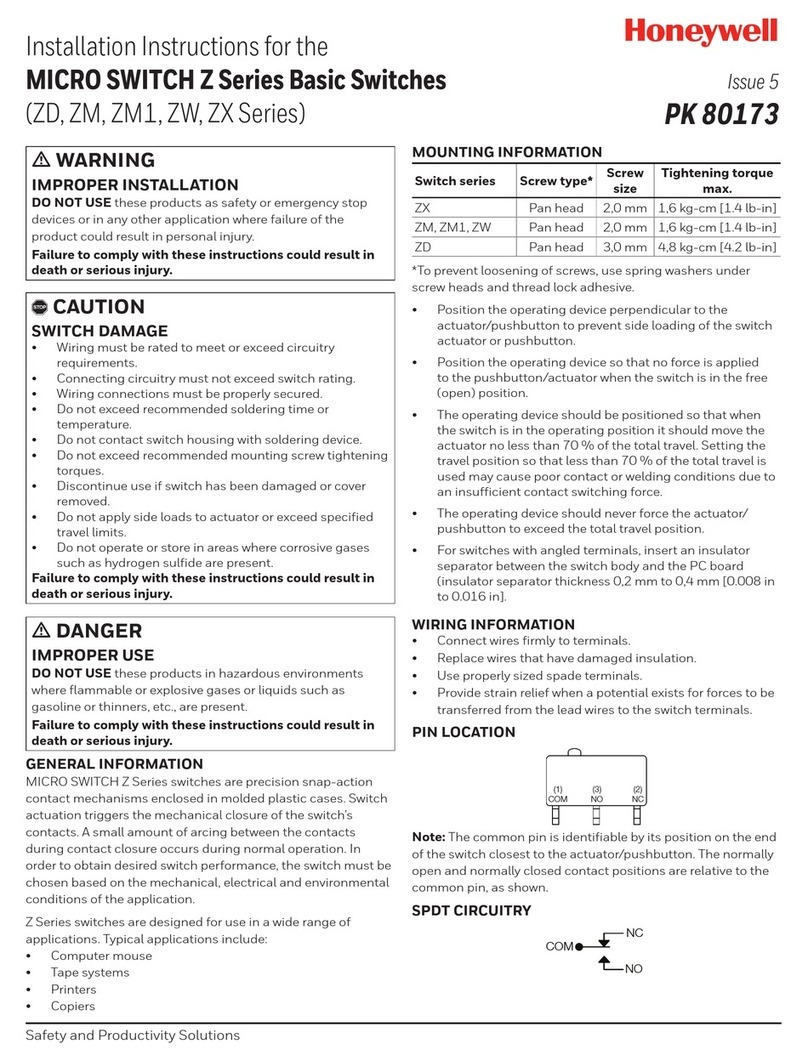
Connection facilities
▷
For 1 mm thick mounting plates, use self-tapping
screws for plastic:
DL..AH, DL..AN: Ø3.5x8mm or Ø4x8mm.
DL..KH, DL..KN: Ø3.5 x16 mm.
1 Fit the DL.
64 (2.5") 45 (1.8")
54,5 (2.1")
ø 2,7 x 16
(ø 0.11" x 0.6)
Rp ¼
DL..AH,
DL..AN
DL..KH,
DL..KN
ø 2,7 x 8
(ø 0.11" x 0.3")
ø 3,5 x 8
(ø 0.14" x 0.3")
49,5 (1.9")
44,5 (1.7")
M16 x 1,5
28,5 (1.1")
M16 x 1,5
28,5 (1.1")
ø 6,1 (ø 0.24")
2 Connect the pressure line.
▷
DL..A: upon delivery, port 2 is closed off by a
rubber cap.
DL..A
1 = Rp 1/4 (+)
2 = ø 4,75 x 1 mm (+)
3 = ø 4,75 x 1 mm (-)
(4 = Rp 1/8 (-))
2 = ø 4,75 x 1 mm (+)
3 = ø 4,75 x 1 mm (-)
(4 = Rp 1/8 (-))
DL 5–150A
1
2
3(4)
Test
▷Positive pressure, port 1 or 2
▷
Negative pressure, port 3; after unscrewing
port3 also port4
DL..K
1 = Rp 1/4 (+)
2 = ø 4,75 x 1 mm (+)
3 = ø 4,75 x 1 mm (-)
(4 = Rp 1/8 (-))
2 = ø 4,75 x 1 mm (+)
3 = ø 4,75 x 1 mm (-)
(4 = Rp 1/8 (-))
3(4)
2
▷Positive pressure, port 2
▷
Negative pressure, port 3; after unscrewing
port3 also port4
Positive pressure measurement
▷1 or 2 = positive pressure port(+).
▷If port2 is used, close off port1.
▷
3 or 4 = remains open to ventilate the upper
diaphragm chamber.

