Selectronic SP PRO Quick start guide

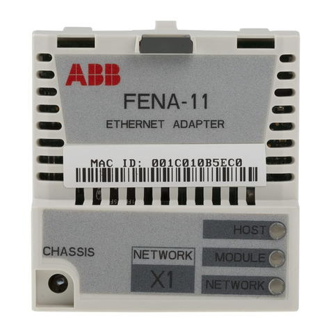
SP PRO Ethernet Adaptor Lead for LAN connection
Installation Notes
IN0031 Revision 01 (005079) –1 of 3
POWER PERFORMANCE PASSION
SP PRO Ethernet Adaptor Lead for LAN connection
Introduction
Connecting a SP PRO series II inverter to a local area network (LAN) requires an optional adaptor lead
and a simple configuration of SP LINK. Once connected the SP PRO can be accessed via
SP PLINK from any PC computer connected to the same LAN.
The adaptor lead is also suitable for connection to the SP PRO series I with the addition of a “Powered
Console DB9M-RJ45 lead” (Stock code 004349).
Attention
When using the Ethernet Adaptor lead connection both the USB and the COM1 connections are not
available. If a USB connection is required at the SP PRO inverter then first unplug the Ethernet adaptor
from the DB9 connector in the SP PRO, plug in the USB lead and connect to computer. When the USB
connection is concluded simply unplug the USB lead and reconnect the Ethernet lead. The SP PRO will
again be available on the LAN.
Overview
The diagram shows the configuration of the Ethernet adaptor lead.
Ethernet adaptor
lead plugged into
SP PRO
PC connected to the
LAN
Connect to LAN via Hub,
wireless router or wired
rounter using network cable

SP PRO Ethernet Adaptor Lead for LAN connection
Installation Notes
IN0031 Revision 01 (005079) –2 of 3
System Requirements
To successfully install the Ethernet Adaptor lead the following system requirements need to be met.
The computer operating system must be Windows XP, Vista, Windows 7 or Windows 8. (PLEASE
NOTE that Windows 8 RT is NOT suitable).
You must have administrator rights for the computer to install SP LINK software.
Your Local Area Network must have an active DHCP server (which is the case for most networks).
The DHCP server automatically assigns the SP PRO its IP address.
Suitable for a SP PRO Series II (revision 20 or greater).
Can be used with a Series I SP PRO with the addition of a “Powered Console DB9M-RJ45 lead”
(Stock code 004349).
Installation
1. Check that the Communication Port 1 Baud rate is 57600. This is the default setting and should be
correct if it was not changed during installation of the SP PRO.
If you are not sure of the Baud rate setting then
Connect a computer with SP LINK installed to the SP PRO inverter using the cables supplied
with the SP PRO and following the instructions in the SP LINK manual (found in the “help”
menu of SP LINK).
Go to the “Configuration Setting” tab and click on “Get SP PRO’s configuration” button.
Click on the “System” tab and check the “Port 1 Baud rate”.

SP PRO Ethernet Adaptor Lead for LAN connection
Installation Notes
IN0031 Revision 01 (005079) –3 of 3
POWER PERFORMANCE PASSION
Unplug the USB lead from the SP PRO series II inverter then plug the Ethernet adaptor
lead into the DB9 connecter at the base of inverter. Screw in the thumb screw on each side of the DB9
plug. This will prevent the Ethernet adaptor lead from falling out.
Using the supplied network cable connect the other end of the Ethernet adaptor plug into your local
network. If the supplied cable is not long enough then any standard network cable may be used.
CONNECTING COMPUTER TO SP PRO
1. Install SP LINK software found on the USB stick provided. (if not already installed). SP LINK must
be version 7.4 or greater.
2. Check that the computer is connected to the LAN
3. Run SP LINK and create a site file following the instructions in the SP LINK manual (found in the
“help” menu of SP LINK).
4. Click on “Connection Settings” under the “Site Information” tab and set Connection Type to
Network.
5. Enter 10001 in the “Port”settings then click “Scan Local Network” button to find the SP PRO
inverter’s IP address. This will appear in the Detected devices box.
6. Double click on the found IP address and this will appear in the “Hostname or IP address” setting.
7. Click the “Connect” button to connect to the SP PRO inverter.
Useful Hints
1. If more than one IP address is detected then note all the IP addresses. Disconnect the Ethernet
Adaptor Lead from the network and perform another “Scan Local Network”. The IP address that
does not appear is that of the SP PRO.
2. If the SP PRO has been disconnected from the network for a period of time then its IP address
may have changed and connection cannot be made. If this occurs then use “Scan Local Network”
to find the new IP address.
3. If you wish to make the SP PRO connection available anywhere on the internet then download
Technical note TN0028 from the web site and follow the instructions. Please note that this
document is only given as a guide and as all network configurations are different Selectronic is
unable to provide any further support.
For further information –http://www.selectronic.com.au or contact the Selectronic Sales Team.
+61 3 9727 6600
www.selectronic.com.au
Retaining screw
Connect this end to
the SP PRO
Connect this end
to network cable
Other manuals for SP PRO
9
Table of contents
