Selkirk ULTRA-TEMP UT Instructions for use

1
SELKIRKCANADA
375 Green Road,
Stoney Creek, ON L8E 4A5
1-888-SELKIRK (735-5475)
Fax: 1-866-835-9624
www.selkirkcorp.ca
(5” to 14” dia.)
FACTORY-BUILT
INSULATED CHIMNEY
Installer: It is of the utmost importance that these UT instructions are
left with the homeowner.
Homeowner: Keep these instructions and maintenance guide in a safe place
forfuturereference.
INSTALLATION INSTRUCTIONS
&
MAINTENANCEGUIDE
(CANADAONLY)
Tested to Standard
CAN/ULC-S604
&
ULC/ORD-C959
PLEASE READ ALL INSTRUCTIONS
BEFORE BEGINNING YOUR
INSTALLATION.
FAILURE TO INSTALL THIS SYSTEM IN
ACCORDANCE WITH THESE
INSTRUCTIONS WILL VOID THE
CONDITIONS OF CERTIFICATION AND
THE MANUFACTURER'S WARRANTY.
A MAJOR CAUSE OF VENT
RELATED FIRES IS FAILURE
TO MAINTAIN REQUIRED
CLEARANCES (AIR SPACES)
TO COMBUSTIBLE
MATERIALS.
IT IS OF THE UTMOST
IMPORTANCE THAT THIS
CHIMNEY SYSTEM BE
INSTALLED ONLY IN
ACCORDANCE WITH THESE
INSTRUCTIONS.
LISTED

2
3
4
4
4
5
5
5
5, 6
6, 7
7
8
8
9, 10, 11
11
11, 12
12
12, 13
13, 14, 15
15
16
16
16
17
18
18
19
CERTIFICATIONLABELS...........................................................................................................................
.
FUELSANDAPPLIANCES...........................................................................................................................
RULESFORSAFETYDURINGINSTALLATION.........................................................................................
GENERALINSTALLATIONRULES..............................................................................................................
TOOLS..........................................................................................................................................................
CHIMNEYSIZING..........................................................................................................................................
FRAMINGDETAILS......................................................................................................................................
CEILINGSUPPORT...................................................................................................................................
ADJUSTABLELENGTH..............................................................................................................................
ATTICINSULATIONSHIELD.....................................................................................................................
FIRESTOPJOISTSHIELD.........................................................................................................................
ELBOWINSTALLATION.............................................................................................................................
ADJUSTABLEWALLSUPPORT...............................................................................................................
WALLBAND................................................................................................................................................
CATHEDRALCEILINGSUPPORT............................................................................................................
ROOFSUPPORT.......................................................................................................................................
ROOFFLASHING.......................................................................................................................................
UNIVERSALROOFBRACEKIT................................................................................................................
ROUNDTOPANDSPARKARRESTER..................................................................................................
STOVEPIPEADAPTER............................................................................................................................
ANCHORPLATE........................................................................................................................................
CHIMNEYOPERATIONANDMAINTENANCE...........................................................................................
OFFSETCHART........................................................................................................................................
CHIMNEYCHARTABOVEROOF............................................................................................................
REPLACEMENTPARTSLIST..................................................................................................................
PRODUCTANDINSTALLATIONINFORMATION....................................................................................
TABLEOFCONTENTS

3
CERTIFICATIONLABELS

4
Thechimneyshould belocatedwithinthebuildingsoas to avoidcuttingor
altering load bearing members such as joists, rafters, studs, etc. If you
require to cut or alter an existing load bearing member, special reframing
methodsarerequiredwhichoften include doubling of adjacent members.
If such a case arises, contact your local Building Code Official regarding
localregulationsandproperinstallationmethods.
Model UT chimney requires 2” (50mm) clearance to
combustible material or as established by support
assembly.
Attachflue pipepartssecurely toeachother, andto theapplianceusing
three sheet metal screws per joint.
• Be sure that ladders are in good condition and always rest on a level
firm surface.
• Be very careful around electrical wiring and be sure it is secured at
least 2 inches away from any part of the chimney. If wiring must be
relocated,hirea professional electrician.
Do not place any type of insulating materials or run any
electrical wiring within the required clearance air space
surrounding the chimney.
FUELS& APPLIANCES:
Model UT chimney has been designed as gravity venting only if the
appliance operates with neutral or negative draft at its outlet. Any
positive pressure in the chimney should use a Selkirk Model PS or
IPS system. Model UT has been designed for connection to liquid or
gas fired residential type appliances and building heating appliances,
in which normally producing flue gas temperatures of 540° C (1000° F)
or less.
All diameters (5”, 6”, 7”, 8”, 10”, 12” and 14”) comply fully with the
requirement of CAN/ULC-S604. Model UT 10” through 14” comply
also to the requirements of ULC/ORD-C959 the 540° and 760° In-
dustrial Chimney Standard.
May also be used with specific factory-built fireplaces listed to UL 127
and CAN/ULC-S610 when specified in the fireplace manufacturer’s
installation instructions.
Before commencing the installation ensure that you obtain any nec-
essary building permits, and that your installation will conform with all
federal and municipal building codes requirements affecting the fuel-
burning appliance and its chimney. This chimney is intended for use
in accordance with:
-National andProvincial Building Code ofCanada,
-CAN/CSAB-149.1-00InstallationCode for Gas Equipment,
-CAN/CSAB-139.00InstallationCode for Oil Burning Equipment;
-Applianceandventingmanufacturers’sInstallationInstructions.
Sectionsof the UTchimney whichpassthrough accessible areas ofthe
building such as closets, storage areas, occupied spaces or anyplace
wherethesurfaceofthechimneycouldbecontactedbypersons or com-
bustible materials must be enclosed in a chase to avoid personal
contact and damage to the chimney.
The chase may be fabricated using standard building materials. Dry-
wall mounted on 2” x 4” studs is typically used in this situation. Except
for installation in single and two family dwellings, factory-built chim-
neys shall be enclosed with approved walls having a fire resistance
rating equal or greater than that of the floor, wall or roof assemblies
through which they pass. and must have a fire resistance rating equal
to or greater than the floors or ceilings through which they pass. The
minimum airspace clearance between the outer wall of the chimney
and the enclosure shall be at least 2 inches.
•Besure that electricallypoweredtools are properlygrounded.
If you are knowledgeable in carpentry and mechanically inclined, you
can take on the task of installing your new venting system. It is impor-
tant that all pertaining installation instructions and local codes are
followed carefully. If you have any doubt concerning your ability or
knowledge of the appliance being connected to your chimney sys-
tem, arrange for a professional installation. Certified technicians
having installed systems many times before and have the knowledge
and experience to perform your installation in a professional and
timely manner.
YOURCHIMNEYHASBEENTESTED,ANDLISTED USINGALL
OFTHESUPPORTS,SHIELDS,ETC.,DESCRIBEDHEREIN.
DELETIONORMODIFICATIONORANYOFTHEREQUIRED
PARTSORMATERIALSMAYSERIOUSLYIMPAIR THESAFETY
OFYOURINSTALLATION,ANDVOIDTHECERTIFICATIONAND
ORWARRANTYOFTHISCHIMNEY
WEARSAFETYGLOVESWHENHANDLING
SHEETMETALPARTSWITH SHARPEDGES
The chimney pipe and fittings must be assembled with locking bands
or stainless sheet metal screws, maximum length of 1/2” (12.70mm)
on all interior joints. Locking bands must be used on all exterior
joints.
RULESFOR SAFETYDURINGINSTALLATION: The ideal location for your chimney is within the building envelope.
In cold climates, the use of external chimneys may result in opera-
tional problems such as poor draft, excessive condensation of com-
bustion products and rapid accumulation of creosote. Under these
circumstances, the installation of the chimney within the building is
strongly recommended.
If the chimney must be installed on an exterior wall it is recommended
thatthe chimney beenclosedbelow the roofline to protect thechimney
fromcoldoutdoortemperatures,thismayhelpreducecondensation, creo-
sote formation and enhance draft. Provide an access door by the Tee
Cap for chimney inspection and cleaning. The exterior enclosure
may be insulated, maintaining the required 2” (50mm) air space clear-
ance to any part of the chimney. Consult local building codes for cold
climate applications.
GENERALINSTALLATION RULES:
Support all offsets with an offset support and adequate strapping.
The minimum clearance to Model UT meansAIR SPACE ONLY. The 2
inch (50mm) clearance to pipe, and the spaces around supports must
not be filled with any type of insulation.
An Attic Insulation Shield must be installed where the chimney passes
into an attic space. It is designed to keep insulation materials or
debris from coming into contact with the chimney. It must accomodate
the amount of insulation as required by the National Building Code.
Where height restrictions will not permit the use of the Attic Insulation
Shield, it is permissible to construct an enclosure with a 2” air space
clearance to the outer pipe all the way to the underside of the roof
deck. In this application you would install a Firestop Joist Shield on
the ceiling side.
At the level where the chimney penetrates the air/vapour barrier, spe-
cial attention is required. Seal the vapour barrier to the Firstop Spacer
or Ceiling Support assembly or Wall Thimble using an appropriate
caulking compound as per the requirement of local authorities.
Do not mix and match with other manufacturer’s products. Use only
UT listed components.
5
121/4”
12 1/4”
12”
13 1/4”
N/A
13”
111/4”
121/4”
11”
16 1/4”
N/A
16”
N/A
N/A
18”
14 1/4”
N/A
14”
N/A
N/A
20”
5” 6” 7” 8” 10” 12” 14”
TOOLS:
YourUTchimneysystemisdesignedforinstallationusing standardbuild-
ing materials and procedures. The following tools/equipment may be
requiredaswellas some others dependingon the locationand structure
inwhich thechimneyis tobeinstalled:
-Safety gloves
-Safetygoggles
-Hammerand nails
-Tinsnips
-Tapemeasure
-Scewdrivers and pliers
-Plumblineand level
-Square
-Keyholesay or powerjig saw
-Caulkinggunandcaulking
CHIMNEYSIZING:
In order to achieve safe, optimum performance of the appliance, ser-
vice life of the chimney, the chimney should be sized correctly for the
connected appliance. In general, the chimney flue should be the
same size as the appliance flue outlet. Installations should be done
in accordance with the applicable installation codes (eg. CSA-B149
for natural gas and propane appliances, and CSA-B139 for fuel oil
appliances)and appliance manufacturer instructions. Plan the in-
stallation of your appliance and chimney in such a way that both
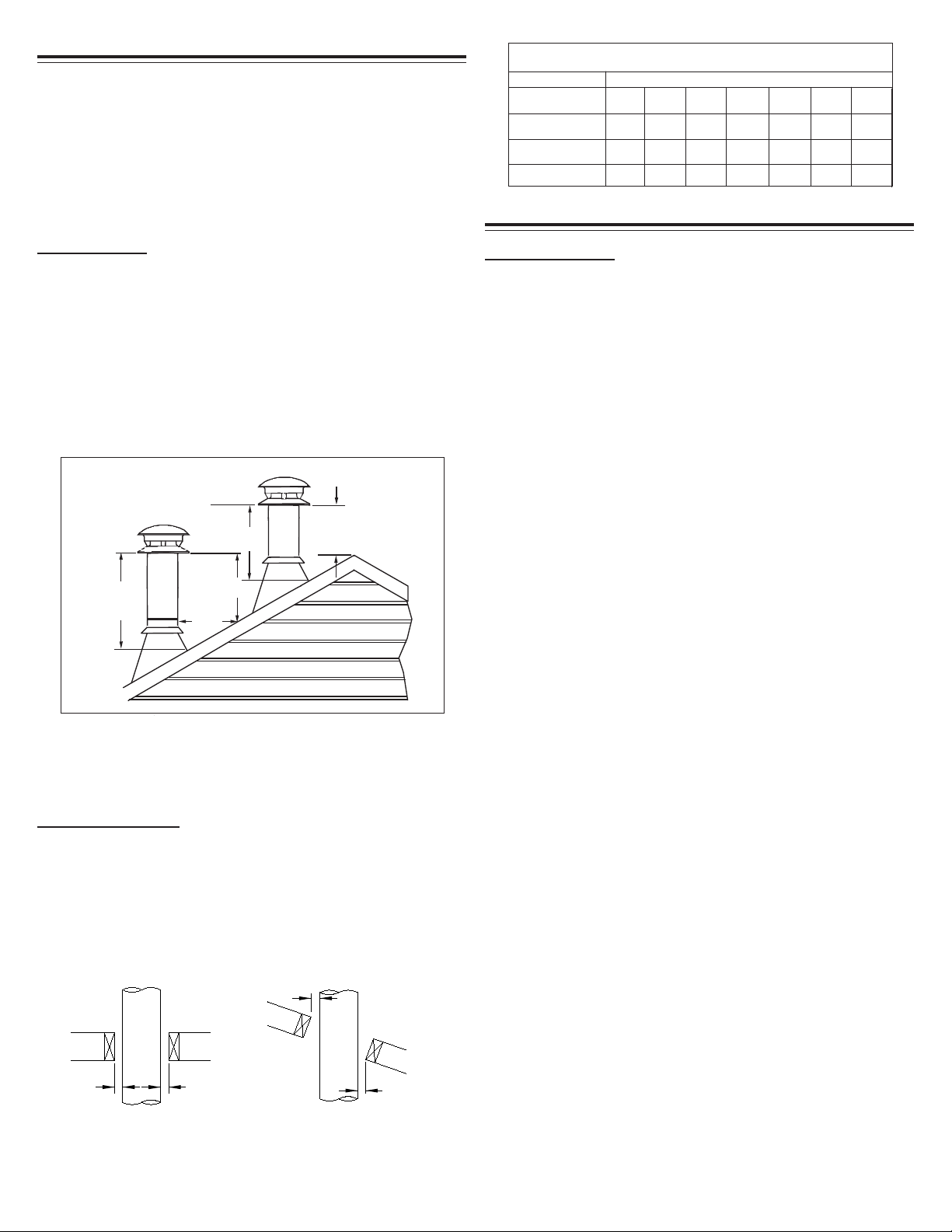
Authority require that the chimney extend not less than 3ft (900 mm )
abovethehighestpointwhereitpassesthrough the roof of a building and
not less than 2ft (600 mm)higherthananyportionof a building within 10ft
(3m) horizontally. SeeFigure1andChart2 in the back ofthese instruc-
tions.
FRAMINGDETAILS:
Plan your installation carefully. If possible, position the appliance so
that the flue outlet is centered between joists, rafters or studs. Drop a
plumb line to the center of the flue outlet and mark this center point on
the ceiling. Lay out and frame all openings ensuring the specified 2”
clearance to combustibles is maintained. All openings should be
square, plumb and in perfect alignment with each other (see Figure
2). For angled roofs, ensure that the framing dimensions are mea-
sured on the horizontal plane (see Figure 3).
3 ft.
(900mm)
min.
2 ft.
(600mm)
10 ft.
(3m)
2ft.
(600mm)
3 ft. (900mm)
min.
FIGURE1
your chimney and flue pipe runs are as short and straight as pos-
sible. By having too long and/or multiple bend installations you can
reduce system draft which can affect the operation, and/or perfor-
mance of your appliance and/or chimney system.
2"
(50mm)
Min
2"
(50mm)
Min
2" (50mm)
Min
2"
(50mm)
Min
INSTALLATIONPROCEDURES:
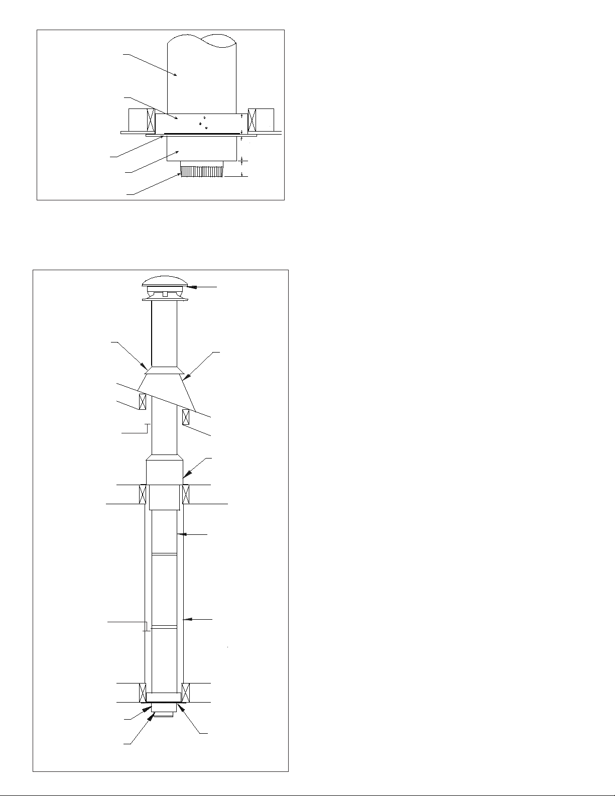
CEILING SUPPORT
TocompleteaproperCeilingSupportinstallation,the following parts may
be required. Ceiling Support available only for 5” to 10” diameters.
- Ceiling Support: For joist supported chimney system.
- Attic Insulation Shield: Where a chimney enters an open attic space.
- Firestop Joist Shield: Installed where the chimney passes from one
living space to another living space or as specified in the listed factory-
builtfireplace installation instructions.
Figure3
TypicalRoofJoist
Framing
Figure2
Typical Joist Framing
FRAMING DIMENSIONS FOR MODEL UT
TO MAINTAIN 2 INCH AIR SPACE CLEARANCE
Chimney Inside
Diameter:
All other framing*
Table 1
CathedralSupport
MODEL UT
Ceiling Support*
The following instructions will assist you in the installation of your
chimney with a Ceiling Support. This support will hold up to 15.25m
(50’) of chimney sections, all of which must be installed above the
support.
1.Frame alevelsquareopening (allfoursides). Insidedimensionsshould
conformtoTable 1.
2. With the Lower Bucket removed, place the upper bucket assembly
into the framed opening from below.
3. Ensure that the support plate is level and flush and drive one nail, 1-1/2”
commonor spiral, partway into eachofthe four (4)nailing areas ofthesup-
port. You may substitute nails with #8x1-1/2” wood screws.
4.Finishnailingthroughallprepunchedholes and fasten the finishing (sup-
port)plate to theceiling(seeFigure4).
5.ReplacetheBucketSectionfromabove. ConnectthepropersizedStove
Pipe Adapter to the first chimney section. Lower this chimney section
down into the bucket section, with the male end pointing upwards as
indicated by the arrow on the chimney label.
6.Additionalchimneylengths above thesupportare simply stacked on,
twistlockedwith a 1/8clockwise turnand securedwith alocking bandat
eachchimneyjoint. Alockingbandissuppliedwitheverychimneylength
and must be used on all chimney joints, interior or exterior. Stainless
steel sheet metal screws (maximum length of 12.70mm (1/2”) may be
substituted on interior joints.
7.Finish the chimneyto itsrequiredheight.
8. If an offset is installed in the system, an Offset Support must be in-
stalled as shown in Figure 13.
9. If the chimney extends 5 feet (1.5 m ) or more above the roof, addi-
tionallateral support isrequired,such as theUniversal RoofBrace Kit.
- Roof Flashing: Required when the chimney penetrates a roof.
- 15° , 30° or 45° Elbow Kits (2 per box with locking bands and elbow
support). NOTE: 45° Elbow kits is available in 5” to 8” only.
The Ceiling Support is for installation below a finished or unfinished
ceilings. The Support fire stop plate fits up against a ceiling, or a joist
opening framed level on all four sides.
- Suitable lengths of chimney: Available in 6”, 12”, 18”, 24” and 36”
lengths. A 48” length is available in 6”, 7” and 8” only.
- Round Top
- Stove Pipe Adapter
*All framing dimensions may be 1/2” larger, but not less than the dimensions mentioned above.
6
1-1/2”
4-1/8”
3”
FIGURE5
CeilingSupport
Bucket Section
Floor, Ceiling Joist
(Framed all 4 sides)
LIVINGSPACE
*FollowApplianceinstructions for properclearance.Ifclearance isnotgiven,use 460mm (18”)min.
*Stove Pipe Adapter
Framed
Enclosure
2” (50mm)
clearance from
chimney to
combustible wall
Chimney Lengths
50mm(2”) minimumair
space clearance to
combustible material
ATTICSPACE
Attic Insulation
Shield
50mm(2”) minimumair
space cleance to
combustible material
RoundTop
CeilingJoist
(Framed all 4 sides)
StormCollar Roof Flashing
Warning: The chimney lengths and its fittings must be assembled
with metal-to-metal joints as furnished. Do not use tape or any
sealing compound (such as tar, mastic, putty or silicone) at the outer
joints. Sealers in the joints may cause the insulation to accumulate
moisture and may cause corrosion or freezing failures.
Chimney Length
Lower Bucket
Upper Bucket
Figure 4
Support Plate
Stove Pipe Adapter
ADJUSTABLELENGTH(AL)
An Adjustable Length (AL) is installed between other components to
establish an exact finished length, where a standard length can not
be utilized. The AL has an over all length of 12” and has an installed
length that adjusts from 2” to 9-1/2”.
The Adjustable Length is available only in diameters of 5” to 8”.
The Adjustable Length must be installed above a fixed length - they
cannot be installed immediately above a support, tee or elbow.
The Adjustable Length slides over the male end of an adjoining
straight length. However, to allow engagement it is necessary to
remove some of the insulation from the inlet end of the Adjustable
Length.
To install:
1. Determine (measure) the finished (installed) length of chimney
needed (DIM “A”) and add 2.25” to the measurement (See Fig. 6).
Note: To facilitate installation, it is recommended that theAdjustable
Length be attached and secured to the lower adjoining segment
before it is installed in the system.
8. Seal the overlap seam and screws with silicone sealant (See Fig. 8b).
7. Re-orient the assembly to the upright position (Male Coupler Up)
and apply pressure to compress the adjoining segments together
until the overlapped edge of the Adjustable Length extends down to
the reference line marked on the standard length. Secure by installing
3 #8 x 1/2” stainless steel sheet metal screws through the pilot
holes in theAdjustable Length and into the outer wall of the adjoining
segment (See Fig. 8b).
6. While still positioned with the coupler end down, insert the standard
straight length into the Adjustable Length (See Fig. 8a).
5. Remove insulation from the inlet (female) end of the Adjustable
Length until the insulation is level with the line marked on the outside
of the pipe (See Fig. 7).
4. Measure the distance (Dim “B”) from that line to the edge of the
Adjustable Length and add 1”. This is the “overlap” distance. On the
adjoining standard length, measure up from the male coupler, the
“overlap” distance and mark a reference line. Make sure the location
of the reference line is measured from the standard length’s male
(coupler) end (See Fig 7).
3. From the male end, measure up the distance Dim “A” + 2.25” and
mark a line on the Adjustable Length (See Fig. 7).
2. Remove the Adjustable Length from the packaging carton and set
it with the male end (coupler end) of the Adjustable Length down to
prevent insulation from spilling out (See Fig. 7).
10. Refer to main installation instructions to continue installing the
remaining system parts.
9. Once the female end of the Adjustable Length is secured to the
adjoining segment, the assembly may be installed in the system.
NOTE: If the Adjustable Length (AL) is installed in a system where it
will be subjected to the weight of more than 4’ of chimney (either
above or below), supplementary support such as an Interior
Resupport (IR) is required.

7
A
B
C
D
E
“A” DIM.
“B” DIM.
“C” DIM.
“D” DIM.
“E” DIM.
7 -1/4”
11”
11-13/16”
13”
20”
8 -1/4”
12”
11-13/16”
14”
20”
9 -1/4”
13”
11-13/16”
15”
20”
10 -1/4”
14”
11-13/16”
16”
20”
12 -1/4”
16”
11-13/16”
18”
20”
14 -1/4”
18”
11-13/16”
20”
20”
5”
11 x 11
6”
12 x 12
7”
13 x 13
8”
14 x 14
10”
16 x 16
12”
18 x 18
16 -1/4”
20”
11-13/16”
22”
20”
14”
20 x 20
DIM “A”
(Non Standard Length)
Remove Insulation
Down to This Line
DIM “A”
+ 2.25”
Fig. 6 Fig. 7
Fig. 8a
InstallSheet Metal
Screws Through
Pilot Holes and
Into Outer Wall of
Standard Length
DIM “A” +
2.25”
Insert Standard Length While Ori-
ented as Shown to Avoid Insula-
tionSpillage
Adjustable
Length
Standard
Length
Adjustable
Length
Fig. 8b
SealOverlap Seam
and Screws With
Silicone Sealant
Standard
Length
Adjustable LengthAttached
to Standard Length
Adjustable
Length
Reference
Line
Overlap
Standard
Length
Mark an Overlap Refer-
ence Line on the Standard
Length. (The Overlap Dis-
tance is Dim “B” Plus 1”)
Standard
Length
Ensure Adjust-
ableLength Edge
isEven With Ref-
erence Line
Standard
Length
DIM“B”
MaleEnd
- It stabilizes the chimney in the framed opening and defines and
maintains the required AIR SPACE clearance to combustibles.
- It prevents heat losses from the dwelling by blocking vertical air
circulation in the space around the chimney.
- It helps provide stability for chimney extending above the roof.
FIRESTOPPING:
Firestopping is required at every joist level. Wherever a chimney
passes through a ceiling or floor, through a wall, or into an enclosure,
it must be firestopped. No firestopping is required in conjunction
with a Ceiling Support installed as shown in Figure 5, the Ceiling
Support provides the firestopping. Firestopping performs the follow-
ing essential functions for both the dwelling and the chimney.
- Together with a fully framed opening (all four sides), controls vertical
and horizontal spread of any fire external to the chimney.
ATTICINSULATIONSHIELD
The function of the Attic Insulation Shield (or a complete enclosure) is
to keep insulation from coming into contact with the chimney. The
height of the Attic Insulation Shield is to meet the insulation level
requirement of the National Building Code. Where height restrictions
will not permit the use of the Attic Insulation Shield, it is permissible to
construct an enclosure with the required air space clearance to the
outer pipe all the way to the underside of the roof deck. In this appli-
cation you would install a Firestop/Joist Shield on the ceiling side.
UT
Chimney
Pipe
Integrated
StormCollar
Attic Insulation
Shield (AIS)
Telescoping
Joist Shield
FIGURE9
- At the level where the chimney penetrates the air/vapour barrier, spe-
cial attention is required. Seal the vapour barrier to the SupportAssem-
bly orAttic Insulation Shield or Wall Thimble or Firestop using an appro-
priate caulking compound as per the requirement of local authorities.
FRAMING DIMENSION CHART
FOR ATTIC INSULATION SHIELD
DIA. OF
CHIMNEY
FRAMED
OPENING
Table 2
For proper installation, the attic opening should be fully framed at 2
inches clearance to the chimney pipe with framing material of the same
dimension as the ceiling joists as per Table 2 and Figure 10. The tabs
on the base plate of the AIS are inserted in the framed opening around
the chimney.
TheAttic Insulation Shield allows for a depth of insulation of 10 inches
plus the depth of the ceiling joists. If insulation is blown in and ad-
heres to the chimney pipe, it should be brushed off to eliminate any
possible contact of this material with the chimney surface.
Nail the AIS base to the framing dimensions with at least 2 nails per
side using 2d (1”) spiral nails or 1” x #8 wood screws. Extend the
telescoping shield down through the framing. See Figures 9 and 10.
FIGURE10
8
X X X X X X X
X X X X X X X
X X X
5” 6” 7” 8” 10” 12” 14”
and install the supplied locking band.
Installtheremaining offset elbow toreturn thechimney backto theverti-
calposition. Againsecureinplacewiththesuppliedlockingband. *Locking
bands and/or stainless steel sheet metal screws can be utilised with a
maximumlengthof12.70mm (1/2”) only onall chimney jointsforming an
offset.
Duringinstallation provide supplementarysupport for theoffsetsection
toavoid undue stressonconnected elbows.
Install an Elbow Support on the vertical length just above the highest
elbow. Securely clamp the supportbandtothechimneylengthjust above
the locking band at the joint. Attach the support straps to the support
bandassembly and nailthem totheframing using 1-1/2”nails or#8x 1-
1/2” wood screws (2 per straps) as per Figure 13.
Never install an elbow in a joist area. Chimney sections must pass
vertically through framed joist areas.
ELBOWINSTALLATION
Elbow Kits (2 elbows, 1 offset support and 4 locking bands).
FIGURE13
Attic Insulation Shield
StormCollar
Elbow Locking Bands
Intermediate/Elbow
Support Straps
Locking Bands Elbow
CeilingSupport
Roof Flashing
If the offset length is more than 1.2m (4’), an intermediate support
must be employed at 1.2m (4’) intervals. Maximum offset length
4.8 m (16’), the intermediate support must be used in conjunction
with an offset support.
Round Top
One pair only of (two) 15 or 30 or 45 degree elbows may be used to
provide an offset in order to avoid cutting of joists and to clear other
obstructions (see Table 3). The vertical run of chimney above an
offset must be supported with an elbow support. Each elbow support
will support 10m (30’) of chimney. If the offset length is more than
1.2m (4’), an intermediate support (plumbing straps not supplied)
must be installed at 1.2m (4’) intervals in conjunction with an offset
support. Maximum offset length is 4.8m (16’). See the Offset Chart for
assistance in selecting your offset. NOTE: Large diameters (10” to
14”) may combine elbow kits for a greater angle up to 45°.
15° Elbow Kit
30° Elbow Kit
45° Elbow Kit
MODEL UT
Framed Enclosure 2”
(50mm) clearance from
chimney to combustible
wall
Elbow Support Band
Roof Joist
(Framed all 4 sides)
Chimney Section
Lower
Bucket
StovePipe
Adapter
Floor, Ceiling Joist
(Framed all 4 sides)
Table 3
The female end of the elbows are not lanced in order to ensure
proper alignment of the chimney system can be maintained.
FIRESTOP JOIST SHIELD
A Firestop Joist Shield is for use in vertical enclosures where the
chimney passes through a floor / ceiling opening, from one living
space to another living space. It is installed from either above or
below the joist. Nail the Firestop Joist Shield using 1-1/2” common or
spiral nails, into the framed opening outlined in Table 1.
Firestop/Joist Shield (JS)
UsedWith UT Chimney
Enclosure
(Drywall, Plywood, etc.)
Ceiling
MinimumClearance
2” Air Space from
Combustibles
Fire Stop/Joist Shield (JS)
Used With UT Chimney
Pipe
Floor
Enclosure
(Drywall, Plywood, etc.)
MinimumClearance
2” Air Space from
Combustibles
Fire Stop/Joist Shield (JS)
Used With UT Chimney Pipe
FIG. 12
UT
Chimney
Pipe
FIG. 11
Enclose the chimney below the Fire Stop Joist Shield to prevent any
accidental contact with the chimney. To prevent blown-in attic insula-
tion from falling against the chimney, either use an Attic Insulation
Shield (AIS) or a full enclosure in the attic. See Section onAttic Insula-
tion Shield.
Install and position the insulated elbow on the vertical chimney length
in the required direction. Fasten the elbow to the chimney length with
the supplied locking band.
Place the required offset chimney length(s) (see Offset Chart for ap-
propriate length(s)) on the elbow. Turn it clockwise to lock it in place
9
A
B
9-1/4”
9-1/4”
10-1/4”
11-1/4”
13-1/4”
15-1/4”
17-1/4”
5”
6”
7”
8”
10”
12”
14”
11”
12”
13”
14”
16”
18”
20”
DIMB
DIMA
L
ADJUSTABLE WALLSUPPORT
As previously mentioned, the ideal location for your chimney system
is within the building envelope. An Adjustable Wall Support is re-
quired when the above mentioned location is not possible.
Theadjustable Wall Support willallowfor an adjustment of2”to 6” from
a combustible vertical wall (see Figures 14a and 16). Pem-studs are
factory installed on both side brackets and the support plate for fast
and easy assembly.
The maximum chimney height above the Wall Support wherther sup-
ported along an interior or exterior wall is indicated in Table 5 and
illustrated in Figure 16.
NOTE: If installing a 10” or larger chimney the Wall Support is a non-
adjustable version which comes with support braces and provides a 2”
clearance when properly installed. Maximum support height is 50 Feet
for 5” through 8” and 40 feet for 10” through 14” (see Figs. 14a & b).
LagScrewsInto
Structure
WallThimble
Shield
WallThimble
FacePlate
Bracket
Pem-Studs
andNuts
CappedCleanout
andRetainer Clips
SupportPlate
WallSupportKit
LockingBand(LB)
InsulatedTee
ModelUT
Chimney
Section
Min.Thru Wall3”
12”to14”
diametersrequires
4-1/2”min
Min.Clearance
To Combustible
CombustibleWall
WallBand(WB)Every
8FeetIf Not Enclosed
UseLockingBands
(LB)on AllJoints
FullEnclosure
Recommended.
BothIndoorsand
Outdoors
SupportPad
FIG. 14a - Wall
Support for 5”
to 8” Chimneys
FIG. 14b - Wall
Support for 10”
to 14” Chimneys
Support
Brace
Support
Plate
If supported along an interior wall in a non-attic area the chimney
must be fully enclosed with a minimum of 2” air space clearance. In
the attic area the chimney an Attic Insulation Shield is to be installed.
Theheight of theAttic InsulationShieldmust accommodate the amount
of insulation height as required by the National Building Code. If it is
not practical to use theAttic Insulation Shield (due to height restrction),
it is permissible to construct an enclosure with a 2” air space clear-
ance to the outer pipe all the way to the underside of the roof deck.
Install a Firestop Spacer on the ceiling side.
If supported along an exterior or interior wall, Wall Bands must be
installed every 8’ to insure chimney stability and maintenance of 2” air
space clearance. In any chimney installation, two points of stabiliza-
tion are necessary hence at least one Wall Band must be installed. It
is desirable to fully enclose an exterior chimney with minimum of 2”
air space clearance to reduce creosote buildup and to promote draft.
The framing dimensions for the Wall Support are ilustrated in Fig. 15
and Table 4.
The following steps will assist you in the installation of the Adjustable
Wall Support. Figure 16 shows a typical Wall Support installation
through a combustible wall.
-Through-The-Wall Length: Attaches to tee branch.
-InsulatedTee w/Plug
-InsulatedWallThimble:Required to passthrough acombustiblewall.
-Wall Band: Requiredtoprovidelateral support tothe chimney.
-RoundTop:To prevent rainand/ordebris from entering inthechimney.
-Stove Pipe Adapter: To connect from the chimney to appliance’s flue
pipe.
-Roof Flashing: Required when the chimney penetrates a roof or a roof
overhang.
The maximum chimney height above an Adjustable Wall Support is
indicated in Table 5 and illustrated in Figure 16, all of which must be
above the support.
“H”
Max.
Chimney
Height
“D”
Distance
from Wall to
Chimney
Support
Plate
Framed
Opening
Vertical
Wall
Studs
FIG. 16 - See Table 5 for Maximum
Chimney Heights based upon
Chimney Diameter and Distance
from Wall
StudsFor
Support
FIG. 15 - Framing for Wall Support
SIZE TABLE4
To complete a proper Wall Support installation, the following parts
may be required:
-Adjustable Wall Support: Intended for a through-the-wall installation
where the chimney has a horizontal connection.
-Suitable Lengths of chimney: Installed above the support.
2. For a non-combustible wall (concrete block or poured foundation),
cut a hole 5mm (3/16”) greater in diameter than the outside diameter
of the chimney.
1. Determine the centre line of the horizontal connection (Chimney
Length through the wall) and frame an opening to the dimensions
specified for the Wall Thimble in a combustible wall (see Table 4
Section Aand Figure 15).
3. After framing in your opening to the dimensions specified in the
Framing Dimensions in Table 1, install the outer half (with the unfin-
ished square plate) of the Insulated Wall Thimble in the outside wall
opening. Secure in place using appropriate fasteners through the
pre-punched holes.
4. Installthe inner half(with blackplate)of the Insulated wallThimblein
the inside wall opening, ensuring that the shield slides into the shield of
the outer half. Once in place and flush against the wall, fasten with ap-
propriatefastenersthrough the pre-punched holes.
5. Assemble the side Brackets (point of triangle facing down) to the
SupportPlate(flange up) by insertingthe threaded studsinto theoblong
slots. Install the supplied nuts on the threaded studs. (see Figures
17 & 18).

10
2
2.5
3
3.5
4
4.5
5
5.5
6
74
73
71
69
66
62
58
52
45
63
62
60
59
56
53
50
45
39
56
55
53
51
49
46
43
38
34
49
48
47
46
44
42
39
35
30
Insulated Wall Thimble
Telescoping adjustment
from 6” to 11”
Insulation
Blanket
Interior Inner
Half of
InsulatedWall
Thimble
Exterior Outer
Half of
InsulatedWall
Thimble
Figure 19
FIG. 20 -SECURINGOFINSULATED TEE CAP
Support
Plate
Insulated Tee Cap Screw to
Secure Tee Cap
Bracket
Tee Cap
Bracket
WARNING: The Insulated Tee Cap must be installed
and secured in place. Failure to install retaining clips
could cause fire, injury or death.
Nutsert
Insulated
Chimney
Section
9. Place the insulated Tee on the support plate ensuring that the
male coupler of the Tee is facing up and the flange on the top of the
plate slides into the female coupler. Insert and secure the Tee Cap
with the attached retainer clips (see Figure 20). In earthquake zones,
secure the Tee to the flange on the support plate by installing 2 stain-
less steel sheet metal screws as per figure 20.
10. For extension of the Tee, slide an appropriate insulated Chimney
Lengththroughthe WallThimble and attachit to the horizontalbranch of
theInsulatedTee with thesupplied lockingband. Make sure thenut and
bolt are facing down to prevent any water from collecting in the locking
band. The insulated length must protrude at least 76mm (3”) through
the wall into the room as per Figure 14a.
Stud and Nut
located to front
of Support
Bracket
Support
Brackets
Threaded Stud
and Nut
located at
rear of
Support Plate
Pre-
Punched
Holes of
Support
Bracket
Slot for Tee
Cap Bracket
Flange Up
FIG.18 - FRONTVIEW OFWALLSUPPORTASSEMBLY
Support
Plate
6. Ensurethat theWallSupport is level,and secure tothe wall through
the pre-punched holes located on the sides of each of the wall support
bracketsusing(8)#14x1-1/2”hexheadlagscrewsor #10 x 1-1/2” wood
screws. You can drill 5/32” pilot holes for the lag screws.
7. Once in its final position and all clearances have been met, tighten
each of the nuts on the threaded studs.
8. Attach the two (2) retainer clips to the bottom of the support plate
and fasten with the supplied nuts and bolts using the two (2) holes on
top of the support plate (see Figure 20).
11. Use a non-hardening high-temperature sealant (500oF) to seal
around the horizontal length where it enters the wall thimble or the
concrete wall.
12. Chimney lengths above the Insulated Tee are simply stacked on
and locked with a 1/8 clockwise turn. Locking bands must be used
on all joints.
13. For lateral stability of the chimney above the support, a Wall Band
mustbeused every 8feet, andat leastone Wall Bandmust beinstalled.
Interiorchimneysmustuse the Firestop JoistShield (JS) inplace ofWall
Bandsifextending through floor /ceiling penetrations.
Distancefrom
Wall to
Chimney 5” ID
Chimney 6” ID
Chimney 7” ID
Chimney 8” ID
Chimney
H(feet)
Max. Height H(feet)
Max. Height H(feet)
Max. Height H (feet)
Max. Height
D (inches)
Wall/Chimney
Table 5 - Wall Support Chimney Height Chart
Support Side
Brackets
Support Plate
Threaded Stud
Support Bracket
Threaded Stud
Nut
Support
Plate
Nuts
Nut
Support Bracket
Threaded Stud
Support
Plate
Threaded
Stud
FIG. 17 - UNDERSIDE VIEW OF
THREADED STUDS AND NUTS
11
76mm
(3”) min.
WALLBAND
The Wall Band is used along an outside wall at 8 ft intervals for lateral
stability. Secure the Wall Band bracket to the wall using two 6d or 2”
spiralnails. For concrete wallsusesuitable masonry fasteners.Thenut
andbolt supplied will fastenthe bandaroundthechimney.
NOTE: Inverting the brackets (brackets mounted above the support
plate) can be accomplished by inserting extra bolts through the oblong
slots of the support side brackets and the support plate as per Figures
21 and 22. Secure with nuts. In this position, the range of adjustability
is limited to 5” from the wall.
Nuts
Slot on
Support
Bracket
Support Brackets
Pre-Punched
Holes of Support
Bracket
Support Plate
w/ Flange Up
Slot for Tee Cap
Bracket
Slot on
Support
Plate
Bolts
FIG. 22- SLOTAREAS
WITH BOLTSAND NUTS
ASSEMBLYOF SUPPORT
BRACKET AND
SUPPORTPLATE
FIG. 21-FRONTVIEWOF
WALLSUPPORT
ASSEMBLYWITH
BRACKETSMOUNTED
ABOVETHE SUPPORT
PLATE
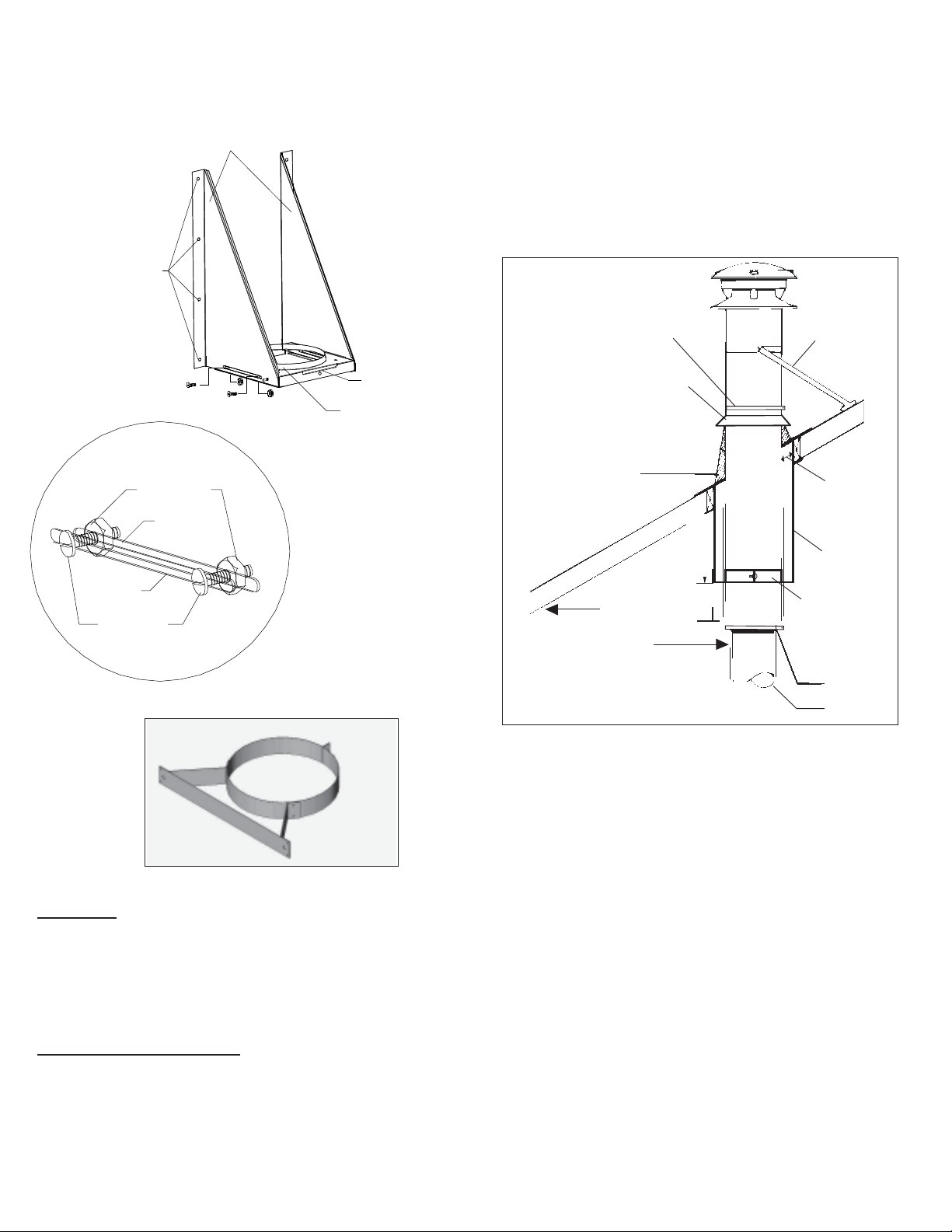
Wall Band Figure 23 - After framing in your opening to the dimensions specified above and
in Table 1, slide the Cathedral Support Box into the joist/rafter open-
ing. Once the box is at the desired location, ensure the box is level
and plumb. Nail the box to the framing using four 2” spiral nails or
equivalent per side. The excess material sticking above the roof can
either be trimmed off before attaching the box to the framing or, after it
is installed the corners can be cut and the excess material folded
down onto the roof deck.
- Install the Support Band on a chimney length at the desiredposition
by tightening the support band with the bolt and nut. Secure the band
to the chimney outer casing by screwing four stainless steel sheet
metal screws through the support band and into the outer casing.
- Lower the chimney length down through the opening in the bottom
of the support box, so that the Support Band makes contact with the
bottom of the Support Box (see Figure 24).
-Cathedral Ceiling Support /w 4 painted ceiling trim angles
-RoofFlashing w/ StormCollar
CATHEDRALCEILINGSUPPORT
A Cathedral Ceiling Support is available for 5” and 6” diameters chim-
ney only. For other diameters, a roof support can be used to suspend
the chimney below the roof. To complete a proper Cathedral Ceiling
Support installation, the folllowing parts may be required:
NOTE: The male coupler of the chimney length must be pointing
upwards as per the arrow on the chimney label.
- The bottom chimney length should protrude into the living space so that
proper clearances are maintained at the adapter (see Figure 24).
- The Cathedral Ceiling Support Box is manufactured to an overall
outer dimension of 12” x 12” (305mm x 305mm). Therefore, the sug-
gested framing to fit the box is 12-1/4” x 12-1/4” (311 x 311mm).
The following instructions will assist you in the installation of your
chimney with a Cathedral Ceiling Support. This support will hold up
to 30’ of chimney, of which 15’ can be suspended below the box.
Chimney joints made below the support must be secured with lock-
ing bands.
-Suitable lengths of chimney
-Stove PipeAdapter
-TrimCollar
-RoundTop
Flashing Minimum
50mm 2”
air space
clearance
Roof
Brace Kit
StormCollar
Locking
Band
Stove
Pipe
Adapter
Follow
Appliance
Instructions
for proper
connector
clearance
Support
Band
Cathedral
Ceiling
Support
FluePipe
RoundTop
Figure 24

12
158
7
6
4
32 910
1
26
453 78910
11
11
3”
ROOFFLASHING:
Ensure that you have the proper roof flashing by checking your roof
pitch using a level and two rulers (see Figure 27) or by using a roof
pitch card.
12”
Ruler Level
Roof
Figure 28
Figure 27
Shingles
Nails
Flashing
7.Attach the Roof Brackets to the chimney plates. Centre the assem-
bly in the roof opening, ensuring that a 2” clearance to combustible is
maintained.
8.Adjust Roof Brackets to the roof pitch and tighten nuts.Attach to the
roof with six (6) large wood screws per bracket
with the inner-most screws going into the rafters or headers (See
Figure 25 & 26).
9. Additional chimney lengths above the support are simply stacked
on and locked with a 1/8 clockwise turn.
10. Locking Bands must be used on all exterior joints.
11. Finish the chimney to its required height. If the chimney extends
1.5 m (5') or more above the roof, a Universal Roof Brace Kit is
required (see Figure 36).
Apply a bead of
silicone caulking
along the seam
where the plate
meets the cone.
Apply a bead of
silicone caulking
along the back
seam of the
cone
ROOFSUPPORT
The following instructions will assist you in the installation of your
chimney with a Roof Support. This support will hold up to 9.0 m (30')
of chimney of which 6.0 m (20') may be suspended beneath it.
1. Frame a rectangular roof opening to provide a 50mm (2") minimum
clearance from combustible materials (See Figure (25).
2.Bend both chimneyplates at thevertical slots tofitthe outside curva-
ture of the chimney length (Figure 25).
Install additional chimney sections and lock together by turning clock-
wiseuntil the twosections lock togethertightly. Locking bands mustbe
usedatalljoints. Continueinthis manner until the required height above
theroof is achieved.
Chimney sections installed below the Cathedral Support are locked
together from below by turning counter-clockwise until tightly locked
together with each joint being secured by locking bands which are
provided. Do not offset the chimney below the Cathedral Support.
Figure 25
Figure 26
Flashing
StormCollar
Roof Support
50mm (2”) min.
clearance
InsulatedChimney
Length
FramedOpening
ChimneyPlate
Carriage Bolt
50mm (2”) min.
clearance
Chimneylength
Bend to fit curve of
chimney
Roof Bracket
Large wood screws
provided
Smallsheet metal
screws (provided)
5. Using the bent chimney plate as a template, drill 3/32" holes in the
outer casing of the chimney (do not penetrate more than 12 mm (1/2'’)
into the chimney). Attach the plate with the small sheet metal screws
provided.
6. Install the second plate in a similar manner on the opposite side of
the chimney length.
3. Determine the chimney plate position on the chimney casing (See
Figure 26).
4. Install two (2) carriage bolts per chimney plate in the square holes.
Once you have marked and located the area where the chimney will
come through the roof, center, position and prepare the roof area by
removing shingles, shingle nails and cutting the roofing material.
Frame a RECTANGULAR opening to suit the pitch of the roof and
ensure that a 2” (50mm) clearance is maintained to combustibles on
all four (4) sides. This is done before extending the chimney above
the roof. Do not nail the flashing to the roof at this time as ajustments
may be required.
Roof Pitch is 3/12
13
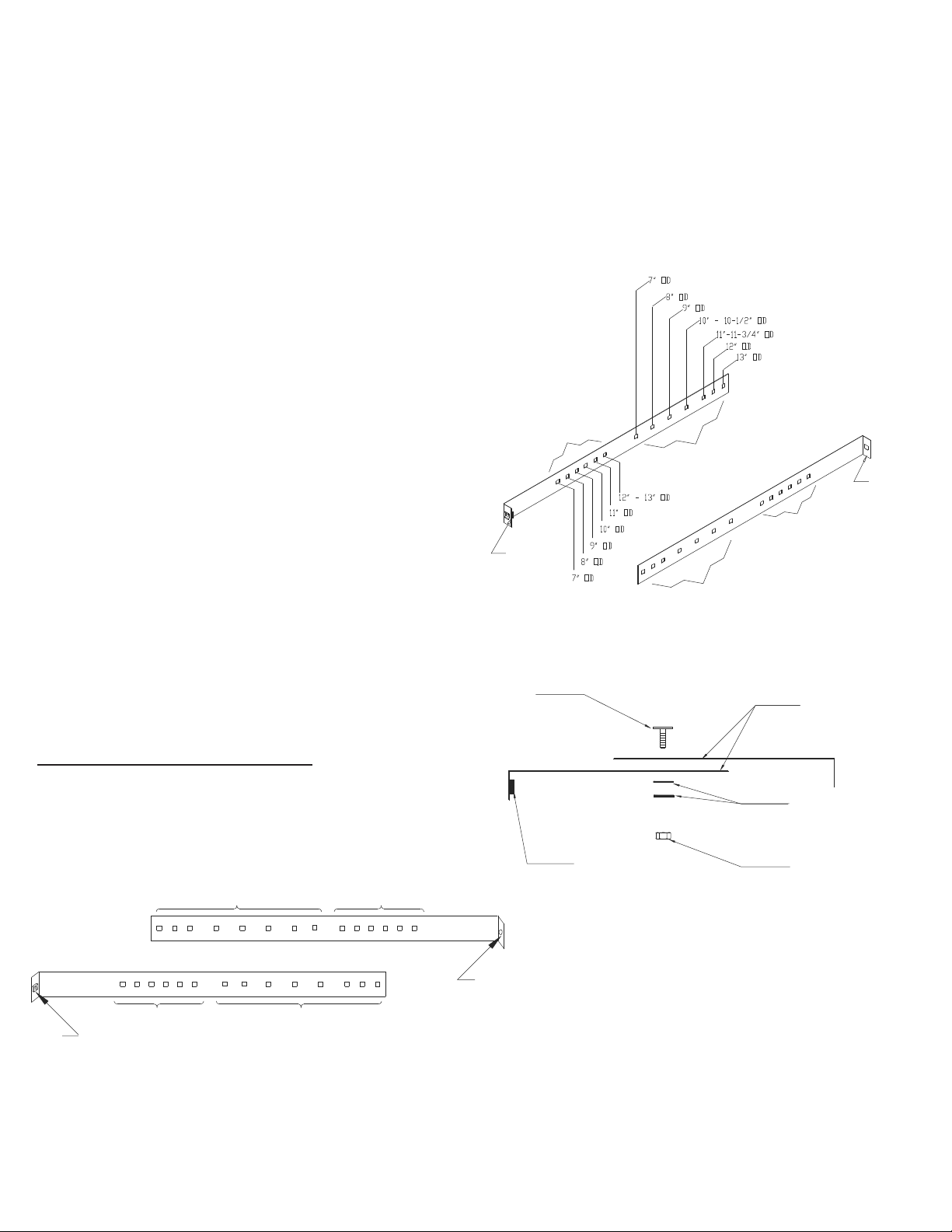
HEAVYDUTYUNIVERSALROOFBRACEKIT
The Chimney, Flashing and Storm Collar may be painted with a heat
resistant rust proofing paint when enclosing of the chimney is not
possible or if exposed to wind driven ocean spray. Salty humid air
causes metal to corrode faster than air with normal humidity. This will
extend its life and improve the appearance and could be matched with
the roof shingles. To improve adhesion to the chimney, degrease,
clean and prime before painting. Follow the paint manufacturer’s in-
structions.
Continueaddingchimneylengthsuntiltheproperheightisachieved(see
Figure1and Chart 2). Install aRoundTop. TheRoundToppreventsentry
ofmoisturewhichmightleadtoprematuredeteriorationofthechimney.
A Rubber Boot Flashing Kit is available as an option for passing
through a corrugated or metal roof. See separate instructions pack-
aged with the Rubber Boot Flashing Kit. On metal or steep roofs, it is
recommended that an ice deflector or “cricket” fabricated from heavy-
guage galvanized steel be installed. The wedge-shaped deflector is
installed 2” from the chimney on the upper slope. Its function is to
split ice and snow as they slide down the roof, preventing damage to
the chimney.
Slide the top edge (nearest the roof peak) of the flashing under the
roofing shingles. At least half of the flashing (top and sides) should
be UNDER the shingles and the lower end OVER the shingles to
provide a watershed. Trimming off the shingles may be neccessary
around the cone of the flashing for a better fit. On existing roof appli-
cation, lower a chimney length into the flashing opening and twist
lock in place and secure with a Locking Band. Ensure that the chim-
ney is level and plumb before nailing the flashing to the roof.
Nailthe flashing totheroof deck (alsounderthe shingles) alongtheup-
per edge and down each sides with 12 nails with neoprene washers or
covertheheadswithasuitablenonhardeningwaterproof caulking. Seal
the shingles to the plate in the same manner. As a precaution, apply a
bead of caulking along all seams of the flashing as per Figure 28.
Applyanon-hardeninghightemperaturesilicone caulking just above the
top of the flashing cone where it meets the chimney casing. Slide the
Storm Collar through theapplied caulkingand place intoitsfinal position
toensure a waterproofjoint. Applyadditional caulking abovethe Storm
Collarasrequired.
The HDURBK will provide lateral support to the chimney above the roof
line. TheHDURBK isrequiredwhenthechimneyextends 5feet(1600mm)
or more above the roof penetration. The kit contains Telescoping Legs,
Support Band, Roof Angle Brackets and hardware package.
Holes used to assemble Support
Band
Holes used to attach
Telescoping Legs to
Support Band
Support Band Holes Identifier
Holes used to assemble Support
Band
Holes used to attach
Telescoping Legs to
Support Band
Cage
Nut
Tab for
2” Bolt
Figure 29
The HDURBK accommodates most models of chimneys with outer
diameters ranging from 7" through 13". For larger diameter a suitable
Bracing System would need to be constructed (guy wires).
NOTE: Different holes combination can be selected as required.
ToInstall:
A. Measure the outside (OD) diameter of your chimney.
B. From the row of holes (see Figures 29 and 30), select the hole in
each half that corresponds to the outside diameter identified with
the chimney being installed. Place the two halves together. Insert
an elevator bolt through the chosen holes (Ex - for a 10” OD
chimney, place the elevator bolt through the holes identified for 10”
OD). The elevator bolt should be oriented as shown in Figure 31.
Secure the center bolt with washers and 1/4” flanged nut (see
Figure 31). NOTE: On smaller diameter chimneys the excess
band material can be cut off.
Cage Nut
Assembly of
Universal
Support Band (2
Halves)
Tab For
2” Bolt
Holes for Telescoping Legs
to Support Band
Holes for Support Band
Holes for Support Band
Holes for Telescoping Legs
to Support Band
Figure 30
Topview assembly of Support
Band - Elevator Bolt, Washers
and Nut
Hex Nut
Flat Washers
Support Band
Halves
Elevator
Bolt
Cage Nut
Figure 31
C. Form the band into a circle (see Figure 32) and loosely connect
tabs using the supplied 2” bolt into the cage nut located on one
of the two formed tabs.
D. Select the hole in each half that corresponds to the OD of the
chimney. Insert an elevator bolt in each of the holes (1 per side).

14
Elevator
Bolt
Angled end of Leg
Wing Nut
Elevator
Bolt
Angled end of Leg
Wing Nut
Assembly of
Telescoping Legs to
Support Band
Flat Washers Flat Washers
Lock Washer Lock Washer
Smaller Diameter Leg
Roof Shingles
Rafter or
framing
structure
Securing
Angle Bracket
2” Lag Screw
K. The two telescoping legs should form an angle of about 60° to
give support to the chimney in all directions. The angle of the
telescoping legs should be approximately 45° from vertical when
fastened to the roof (see Figures 34 & 36).
NOTE: Do periodic inspections of all fasteners including the securing
screws as high winds can cause the chimney system above the roof
to vibrate and in time loosen some of the fasteners.
Figure 34
Figure 35
Universal Support
Band formed into a circle
2” Bolt
Cage Nut
One of 2 halves
of Support Band
One of 2 halves
of Support Band
Elevator
Bolt
Flat Washer
Figure 32
E. Position the Support Band approximately two thirds of the way up
the chimney height (see Figure 36). The preferred location is
next to a joint, immediately above or below a Locking Band.
Secure Support Band by tightening the 2” bolt. NOTE: Only one
chimney joint should be above a Roof Brace Kit. An additional
Roof Brace Kit may be required for taller systems.
G. Place a flat washer on the elevator bolts and attach the top portion
of each of the telescoping legs to the 2 elevator bolts on the Support
Band with washers and nut (see Figure 34). Leg can be bent at an
angle using the claw of a hammer.
H. Attach the other end of each telescoping leg assembly to anAngle
Bracket using one (1) 1/4-20 X 1” bolt and nut (see Figure 35).
Preparation of Telescoping Legs:
F. Assemble the telescoping tubes by inserting the smaller diameter
into larger one. Thread the securing nut to the securing bolt then
thread this assembly into nutsert. Tighten firmly against the
smaller tube which will lock them together (see Figure 33). Repeat
for the other telescoping leg assembly.
Smaller Diameter
Telescoping Leg
Larger Diameter
Telescoping Leg
Securing Bolt
Nutsert
Assembly of Telescoping
Legs with securing
screwand nut Securing Nut
Figure 33
I. Determine the location of the two Angle Brackets on the roof
structure. Ensure the fasteners are into rafters or framing and
not just roof sheathing. Secure the Angle Brackets to the roof
structure using two (2) 1/4 X 2” lag screws per brackets (see
Figure 35). Apply a thin layer of caulking under the angle bracket
(before securing in place) as well as over the lag screw heads.
J. Make sure the chimney is level and plumb. Check all required
dimensions and angles, adjust if necessary. For added security,
we recommend that you secure the inside and outside tubes
together using # 8” x 1/2” stainless steel self tapping screw to
permanently lock them in place.

15
RoundTop
Upper Leg
Lower Leg
Angle
Bracket
2” Lag
screws
10’
MAX
2/3rd
of HT.
Securing Screw
Placement of
Universal Roof Brace Kit
B
C
A
TYPE HT ROUND TOP - 5” to 8” only (10”, 12” and 14” have a
different design)
AttachtheType HTRoundTop tothe chimney by sliding it over the chim-
ney length. ensure that the three (3) vertical tabs are located on the
outside of the chimney length and that the RoundTop sits flush on the
top surface of the length. Wrap the band snug to the bottom of the 3
tabs and secure in place with the supplied nut and bolt.
Chimney
Dia.
5”
6”
7”
8”
FIGURE37
A
7”
8”
9”
10”
B
10”
12”
14”
16”
C
5”
5-1/2”
6-1/4”
7”
Figure 36
Some Selkirk Tops (CT) have a nominal inch diameter expanding
utility attachment adaptable to Selkirk Selkirk Chimney and other prod-
ucts of like internal diameter. To attach securely:
1. Loosen screw on top of collar and squeeze bottom to allow collar to
enter pipe.
2. Press down evenly on lower skirt until it contacts upper end of pipe.
3. Tighten screw on collar to expand lower end and clamp to inside of
pipe. Keep tightening screw until collar is expanded and fully tight.
SPARKARRESTER (Part No. SA)
For 6” to 8” diameters a pre-formed Spark Arrester is available. See
separate instructions packaged with the Spark Arrester.
Spark
Arrester
To Install:
1. Place the pre-formed SparkArrester directly over the dome and skirt
of Round Top (Figure 2).
2. Ensure that the flanged end of the SparkArrester is on top of dome
and the bottom folded edge overlaps the skirt.
Ifclogged:
If the Spark Arrester becomes clogged with creosote, it should be
cleaned or replaced. Remove Round Top by removing cinch band.
Lightly tap away (from the outside of the Spark Arrester) any creosote
residue. If necessary use a soft bristle brush for assistance. If Spark
Arrester is to be removed from the Round Top, release the bottom
edge of the SparkArrester from the skirt edge and raise SparkArrester
from Round Top.
Round Top
Cinch Band
UT
Chimney
Length
FIGURE39
FIGURE38

16
With a new chimney installation, the chimney should be inspected at
least once every 2 weeks during the heating season to determine if a
creosote or soot buildup has occured. When familiar with the appliance
and chimney characteristics, the chimney should be inspected at least
once every 2 months during the heating season.
Ifcreosote or soot hasaccumulated, itshouldberemoved to reduce the
risk of a chimney fire. Depending on the rate of buildup, as you learn
whatis going onin thechimney, you canadjustyour cleaning schedule.
If you have any doubts about your ability to clean the
chimney,orifthedepositsareveryheavyandhardtoremove,callacertified
chimneysweep. Donot try toburn themoff.
Ifchemicalcleanerisusedto assist in cleaning your chimney,makesure
it is a product which is non corrosive to the chimney liner. The optimal
methodfor cleaning a chimneyisbya mechanical brushingof thechim-
neyinconjunctionwithacompleteevaluationof the system by a certified
chimneysweep. TheNationalFireCodeof Canada states: “Every chim-
neyflueandfluepipeshallbeinspected and cleaned annually or as often
as maybe necessary, to keep the chimney and flue pipe free from dan-
gerousaccumulations of combustibledeposits”.
CHIMNEYFIRESANDWHATTODOABOUT THEM:
Your Selkirk chimney is not intended or designed for use as a combus-
tionorfirechamber. Ifthefireinyour appliance has gotten out ofcontrol,
or if you suspect a chimney fire for any reason, follow these steps:
1. Immediatelyclose all dampers and/orairentrance to your appliance.
2. Alertyourfamily to thepossible danger.
3. Inspectyourapplianceandchimneyfor possible fires, if in doubt,alert
yourFireDepartment.
4. Do not use salt or water on the fire. Salt is corrosive and water will
causeadangerous steam explosion. Youmaybe able to controlthe fire
byusingashes, sand orbaking soda,since bakingsoda isan ingredient
usedfor dry chemicalfireextinguishers.
5. Donot continue touseyour appliance untilitand your chimneyhave
beenthoroughlyinspected by acertified servicetechnician.
6. After a chimney fire, when it is safe to do so, check internal locations
such as the attic and under the roof and keep watching for two or three
hours. Theremaybe delayed smoldering andsubsequent ignitioneven
if the fire inside the chimney has been controlled.
The Anchor Plate may be used for adapting the UT chimney to a
“Listed” Factory-Built Fireplace certified for use with Model UT.
NOTE: It is of the utmost importance that theAnchor Plate be installed
in accordance with the manufacturers installation instructions sup-
plied with the “listed” Factory-Built Fireplace.
MODELUTANCHOR PLATE
CHIMNEYOPERATIONANDMAINTENANCE:
The need for chimney maintenance depends on the kind of appliance
and how it is operated. Gas and oil-burning appliances need very little,
butwood-burningappliances may need agreat dealof chimneymainte-
nance.
IMPORTANT
Burningwood produces creosote, soot,and flyashwhichtend to collect
inchimney flue and on terminationpartscausingreduced flow ofgases
through the chimney. Check top weekly for excessive accumulation of
thesenormalcombustion productsand clean as necessary. Ifthe spark
arresterbecomes cloggedwithcreosote,itshould becleanedorreplaced.
4. Always secure all single wall flue pipe joints with a minimum of 3
screws.
5. Obtain proper attachment parts for the appliance end and for the
entryto the chimney.
6. Locate or support the flue pipe to avoid contact of damage.
7. Caps or plugs for single wall tees should be secured against fall-
ingout and designedsothey can’t leak creosoteorrain.
The connection of a single wall base tee or single wall flue pipe or
double wall flue pipe to the insulated chimney must be secured with
the screws supplied in the Support carton. The use of a stove pipe
adapter is recommended with the first length, this will provide a posi-
tive connection between the insulated chimney and the appliance
connector. The Stove Pipe Adapter is inserted into the female end of
the first insulated chimney length and extends beyond the ceiling
support approximately 32mm (1-1/4”). For a Cathedral Support and
Wall Support application, the stove pipe adapter is inserted into the
female end of the exposed chimney length and extend into the room
and held in place with the finishing collar secured with 4 screws
which is used to attach the stove pipe adapter to the finishing collar.
Installinter-connecting fluepipe followingtheappliance manufacturer’s
instructions,andappropriatebuildingcode requirements keeping in mind
that the flue pipe run should be as short and straight as possible. All
joints should be secured in place with three (3) sheet metal screws.
Besidesfollowingtheapplianceinstructions for flue pipe, other rulesthat
shouldbetaken into account:
To comply with the National Building Code of Canada the single wall
base tee can be installed with a 229mm (9”) minimum airspace
clearance between connnecting single wall material and combus-
tible products provided that the flue gas temperature does not exceed
400° C (750° F) (most oil fired appliances). Otherwise, the minimum
air space clearance must be 450mm (18”). Refer to the appliance
installation instructions for the proper chimney requirements.
STOVEPIPEADAPTER:
Connectonlytolowheat(liquidfuelorgasfired)applianceswithcontinu-
ous flue gas temperatures below 540° C (1000° F). When installing a
factory-builtfireplacerefer to the fireplace installationinstructions forthe
properchimneyrequirements.
1. Never enclose single wall flue pipe, even at 18 inches clearance.
2.Neverrunit through ceilingsorfloors, or windows.
3. Don’tuse singlewall flue pipe outdoors.
PAINTINGOFTHEEXTERIORCHIMNEY
If the chimney cannot be enclosed it is highly recommended to paint
all exterior chimney, including the roof flashing and storm collar with a
heat resistant rust proofing paint when the chimney is exposed out-
doors to wind driven ocean spray. Salty humid air causes metal to
corrode faster than air with normal humidity. This will extend its life
and improve the appearance. To improve adhesion, degrease, clean,
prime before painting. Follow the paint manufacturer’s instructions.

17
AA
BBAB
AB
AABBAB
AB
AABBAB
AB
15/16
2-1/4
3-3/4
5-1/4
6-7/8
8-1/8
10
12-3/4
14-3/8
17-1/4
13-1/8
8-1/4
12-7/8
18-5/8
24-1/2
30-1/4
34-7/8
41-7/8
52-1/4
58-7/8
68-3/8
53-3/8
340
444
576
708
840
953
1104
1341
1472
1605
1841
3-1/2
5-15/16
8-15/16
11-15/16
379
517
532
669
745
821
958
15/16
2-1/4
3-3/4
5-1/4
6-7/8
8-1/8
10
12-3/4
14-3/8
17-1/4
13-1/8
9-1/8
13
19-3/8
25-5/16
31-1/8
35-3/4
42-5/8
53-1/16
58-7/8
69-1/4
54-1/4
90
150
228
303
379
517
532
669
745
821
958
394
499
630
762
894
1131
1158
1395
1527
1659
1895
15/16
2-1/4
3-3/4
5-1/4
6-7/8
8-1/8
10
12-3/4
14-3/8
13-1/2
13-1/8
8-13/16
13-7/16
19-1/4
25
30-1/2
35-7/16
42-3/8
52-7/8
58-5/8
69
54
15/16
2-1/4
3-3/4
5-1/4
6-7/8
8-1/8
10
12-3/4
14-3/8
13-1/2
13-1/8
8-5/8
13-3/16
19
24-7/8
30-3/8
35-3/16
42-1/8
52-1/2
58-3/8
68-3/4
53-3/4
105
164
241
317
395
530
545
681
758
835
972
407
511
643
775
907
1144
1171
1407
1539
1672
1908
407
524
656
788
920
1156
1184
1420
1552
1684
1921
120
205
313
421
529
722
744
937
1045
1153
955
304
389
497
605
713
906
928
1121
1229
1337
1144
120
205
313
421
529
722
744
937
1045
1153
955
305
390
498
606
713
906
929
1122
1230
1337
1144
140
225
333
441
548
742
764
958
1065
1173
980
356
441
549
657
765
958
980
1173
1281
1388
1196
140
225
333
441
548
742
764
958
1065
1173
980
384
469
577
685
793
986
1008
1201
1309
1417
1224
105
164
241
317
395
530
545
681
758
835
972
OFFSETCHARTCHIMNEYINSTALLATION(5” to8”only)
It may be necessary to offset the chimney in order to clear a joist or an obstacle. The three (3) charts below will assist you in selecting the proper combination
of elbow angle and chimney length(s) that will provide the necessary degree of offset within an available height.
1. Select the column with the proper chimney
diameter of your system.
2. Determinethedistance ofthe offset requiredby
dropping a plumb line for an accurate measure-
ment. Theoffset ismeasured atthe chimneycen-
tre line as per the "A" Offset measurement in the
diagrambelow.
3. On the chart, find the predetermined distance
(underthe "A"column) required for the 15oelbow.
Forgreater offset,use the30oor 45ooffset charts.
4. After finding the offset, look at the “B” (height)
measurement in the chart to find the specified
height. The appropiate"chimneylengths"required
in between elbows is found in the left hand side
column on the chart.
NOTE:
• UltraTemp chimney can be offsetted us-
ing 15o, 30oor 45oelbows. Combining offsets for a
greaterangleisnot permitted.
• One pair of (two) 15o, 30oor 45oelbows
may be used per interior installation.
• Never install an elbow in a joist area.
Chimney sections must pass vertically through
framedjoist areas.
• Each elbow support will support 30 feet
ofchimney.
•Anintermediate supportmust be used at
4feetintervals inconjunctionwith anelbowsupport.
•Themaximum length ofchimney allowed
betweenelbows is 16 feet.
All measurements in inches.
Construction tolerances + one inch.
Offset
“A”
"B"
Height
45o OFFSET CHART
30o OFFSET CHART
15o OFFSET CHART
none
6"
12"
18"
24"
12" & 18"
36"
12" & 36"
18" & 36"
12"&18"&36"
48"
none
6"
12"
18"
24"
12" & 24"
36"
12" & 36"
18" & 36"
24" & 36"
12"&24"&36"
none
6"
12"
18"
24"
12" & 24"
36"
12" & 36"
18" & 36"
24" & 36"
48"
Chimney
Lengths 7"Diameter
6"Diameter 8" Diameter
5"Diameter
Chimney
Lengths 7"Diameter
6"Diameter 8" Diameter
5"Diameter
Chimney
Lengths 7"Diameter
6"Diameter 8" Diameter
5"Diameter

18
44
42
40
38
36
*36
*36
*36
*36
*36
54
51
48
45
42
39
36
*36
*36
*36
64
60
56
52
48
44
40
36
*36
*36
74
69
64
59
54
49
44
39
*36
*36
84
78
72
66
60
54
48
42
36
*36
94
87
80
73
66
59
52
45
38
*36
104
96
88
80
72
64
56
48
40
*36
114
105
96
87
78
69
60
51
42
*36
124
114
104
94
84
74
64
54
44
*36
134
123
112
101
90
79
68
57
46
*36
144
132
120
108
96
84
72
60
48
36
*36
*36
*36
*36
*36
*36
*36
*36
*36
*36
1/12 2/12 3/12 4/12 5/12 6/12 7/12 8/12 9/12 10/12 11/12 12/12
*UT-36 / *U-36
*UT-24 / *U-24
*UT-18 / *U-18
*UT-12 / *U-12
*UT-06 / *U-6
*T-ITP / *S-IT
*T-EL15KIT / *U-EL15 Kit
*TEL30KIT / *U-EL30 Kit
*T-CSB / N/A
*T-AWS/ *S-AWS
*T-CCSK / N/A
URSP / *S-RSP
*T-LB / *S-LB
*T-AD / *S-CPA
DESCRIPTION
DESCRIPTION
*T-IWT / *S-IWT
*T-WB /*S-WB
URBK / N/A
*T-AP / *S-AP
*T-AIS /*S-AIS
*T-JS / *S-JS
*T-FS / *S-FS
*T-RT / *S-CT
*T-FF / *S-TF
*T-FA / *S-AF6
*T-FAA / *S-AF12
*T-SC / *S-SC
©2019 UltraTemp (Canada) All Rights Reserved 510000 08/19/2019
Requirement # 1 : The code requires that the chimney must extend at least 3 feet (900mm) above the highest point of the roof that it penetrates.
Requirement # 2 : It must also be 2 feet (609mm) above any roof, wall or other obstruction within a horizontal distance of 10 feet (3m).
The following Chart is to assist you in determining the minimum chimney height you will require above the roof. You may need to add to
this height as nearby buildings, trees and other parts of the house roof could interfere with airflow over and around the top of the
chimney and affect its performance. If you think a nearby obstacle could affect draft, you might want to install one or more additional
lengths.
CHART2 - CHIMNEY HEIGHT ABOVE THE ROOF
DISTANCE
FROM PEAK
10 Ft
9 Ft
8 Ft
7 Ft
6 Ft
5 Ft
4 Ft
3 Ft
2 Ft
1 Ft
CHIMNEY HEIGHT ABOVE ROOF (INCHES)
PITCH OF ROOF
* Defaulted to 36" to meet requirement #1. Both requirements (#1 and #2) must be met.
• If the chimney extends more than 5 feet or more above the roof, a Universal Roof Brace Kit is required.
•Alllengthsabovetheroofmusthavelockingbandsatalljoints. ThiswilleliminatetheriskofsectionsbecomingundonebelowtherooflinewhentheRoundTop
isremovedwhen inspections andcleaningofthe system isbeingdone.
All measurements are in inches with the exception of "distance from the peak" being in feet.
REPLACEMENT PARTS LIST
ULTRATEMP
PARTNO.
5” - 8” / 10” - 14”
36" Chimney Length
24" Chimney Length
18" Chimney Length
12" Chimney Length
6" Chimney Length
Tee with Insulated Plug
15o Elbow Kit
30o Elbow Kit
Ceiling Support
Adjustable Wall Support
Cathedral Ceiling Support Kit
Roof Support
LockingBand
Stove Pipe Adapter
InsulatedWallThimble
WallBand
Universal Roof Brace Kit
Anchor Plate
Attic Insulation Shield
Firestop Joist Shield
Firestop Spacer
Type HT Round Top
Flat Roof Flashing
1/12 - 7/12 Roof Flashing
8/12 - 12/12 Roof Flashing
StormCollar
* Specifies chimney diameters (5” to 14”).
ULTRATEMP
PARTNO.
5” - 8” / 10” - 14”

19
INSTALLATION INFORMATION
Leave with homeowner. Homeowner: Keep in a safe place for future reference.
PRODUCT INFO
CHIMNEYMODEL:Ultra-Temp
FLUESIZE________
TOTALHEIGHT_________
INSIDEINSTALLATION OUTSIDEINSTALLATION
CONNECTED TO (type of appliance):
BOILER
FURNACE
LISTED FACTORY-BUILT FIREPLACE
OTHER (specify) ____________________
LOCATION OFAPPLIANCE:
BASEMENT
MAIN FLOOR
OTHER (specify)___________________
INSTALLATION DATE:__________________________________________________
DEALER INFO
DEALERNAME:_______________________________________________________
Address:_____________________________________________________________
City:________________________________________________________________
Province:_____________________________________________________________
TECHNICIAN INFO
TECHNICIANNAME:___________________________________________________
Address:____________________________________________________________
City:_______________________________________________________________
Province:____________________________________________________________
This manual suits for next models
1
Table of contents
Other Selkirk Fan manuals


Popular Fan manuals by other brands

HAMPTON BAY
HAMPTON BAY Dawson 581 645 instruction manual

Ebmpapst
Ebmpapst R1G085-AB05-01 operating instructions

Ebmpapst
Ebmpapst A3G500-AM56-23 operating instructions

Silvercrest
Silvercrest STV 45 A1 operating instructions

Ebmpapst
Ebmpapst VBH0355CTRLS operating instructions

Ebmpapst
Ebmpapst R3G190-AB23-02 operating instructions


Bigassfans
Bigassfans Haiku FR127A-A2 installation guide

Ebmpapst
Ebmpapst S2E300-AP02-50 operating instructions

Tripp Lite
Tripp Lite SmartRack SRFAN1U owner's manual

Ebmpapst
Ebmpapst R2E220-RA38-13 operating instructions

Ebmpapst
Ebmpapst D3G225-CC14-71 operating instructions

Ebmpapst
Ebmpapst D2E097-BI56-50 operating instructions