Sensicast OEM200 User manual

OEM200 MODULE
VERSION 1.0
Hardware Manual

www.sensicast.com
HARDWARE MANUAL
OEM200 Module
VERSION 1.0
Sensicast Systems, Inc.
220-3 Reservoir Street
Needham, MA 02494
Phone 781.453.2555

www.sensicast.com
Part # 2390 – OEM200 Module Hardware Manual
Copyright ©2005 Sensicast Systems, Inc. All rights reserved.
Sensicast®and SensiNet™ are trademarks of Sensicast Systems, Inc. in the United States and/or other countries. All other
trademarks are property of their respective owners.
In the interest of product improvement, information and specifications herein are subject to change without notice.

2
FCC Statement
The A2400 equipment complies with Part 15 of the FCC Rules. Operation is subject to the following two
conditions:
(1) This device may not cause harmful interference; and
(2) This device must accept any interference received, including interference that may cause undesired
operation.
FCC Caution: Any changes or modifications not expressly approved by Sensicast could void the user’s
authority to operate this equipment.
FCC RF Radiation Exposure Statement: The module complies with FCC's RF exposure requirements and
the module must not be co-located or operated in conjunction with any other antenna or transmitter.
FCC Labeling
The module is labeled with its own FCC ID number (RNB-OEM200). If this number is not visible when the
module is installed inside another device, then the outside of the device into which the module is installed must
also display a label with the following wording: “Contains FCC ID:RNB-OEM200”
FCC 20cm RF Exposure To comply with FCC’s RF exposure limits for general population / uncontrolled
exposure, the antenna(s) used for this transmitter must be installed to provide a separation distance of at least
20 cm from all persons and must not be co-located or operating in conjunction with any other antenna or
transmitter.
3
Introduction
This design guide is intended to provide a good understanding of the functionality of the OEM200 module.
The intended audience is the engineer responsible for integrating the OEM200 into a product.
Description and Specifications
The OEM200 is a component of the Sensicast A2400 Wireless Sensor Network Platform – a completely self-
configuring, self-healing, power managed sensor network.
Powered by SensiNet (Sensicast proprietary mesh networking software), the OEM200 is the most reliable mesh
networking radio module on the market today. With its external radio amplification stage, it has a range of
over 1000 feet (outdoors) and 230 feet (indoors, non-line of site). Furthermore, SensiNet uses frequency
diverse radio algorithms to ensue reliable, clear channel communication even in the most harsh radio
environments.
In addition, off-the-shelf A2400 infrastructure hardware and SensiMesh®Gateway software for constructing
and maintaining your mesh network is available from Sensicast.
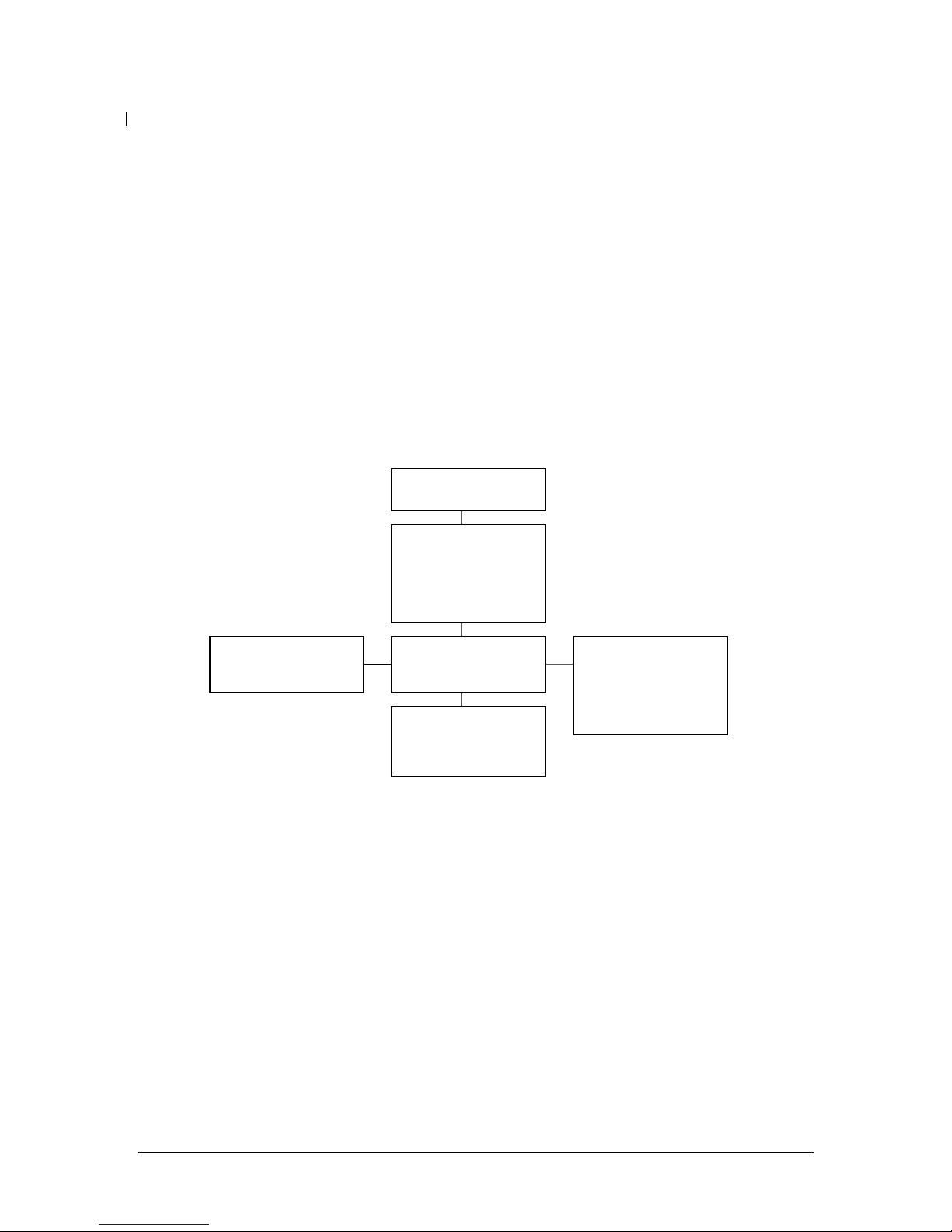
Block diagram
Antenna
There is a PCB “Inverted F” antenna on the device. For best performance, care should be taken to keep metal
components away from this section of the PCB. The PCB will also support an external antenna connector at
J2. However, please note that this product is only FCC certified with the existing embedded antenna. If a user
application requires an external antenna, re-submission with the specific external antenna is required for FCC
approval. For more details, please contact Sensicast.
Radio Transceiver
The radio is under control of the OEM200’s microcontroller and is contained inside the metal shield.
Microcontroller
The SensiNet software, including the sensor API, runs on this microcontroller. It includes onboard flash
memory, RAM, and analog and digital I/O and a 32kHz real time clock.
LEDs
There are three LEDS: red, yellow and green that are firmware controlled.
Antenna
Radio Transceive
r
Microcontrolle
r
Connecto
r
Optional temperature and
humidity sensor
LEDs

4
Optional temperature and humidity sensor
The OEM200 can be preloaded with a temperature and humidity sensor at U7. Please contact Sensicast for
temperature and humidity specifications.
Connectors
The primary interconnection is J1, the 41 position board-to-board, header (Hirose p/n DF9A-41P-1V(20);
mates with: Hirose p/n DF9A-41S-1V(20)) on the bottom of the assembly. (Please note that this header is
common between the OEM200 and OEM100).
Optionally, power can be brought to the board through J3, a two position, right angle wire to board, header
(JST p/n S2B-PH-K-S, mate: JST p/n PHR-2). Here is a schematic drawing of J1 and a list of signal
descriptions for both connectors:
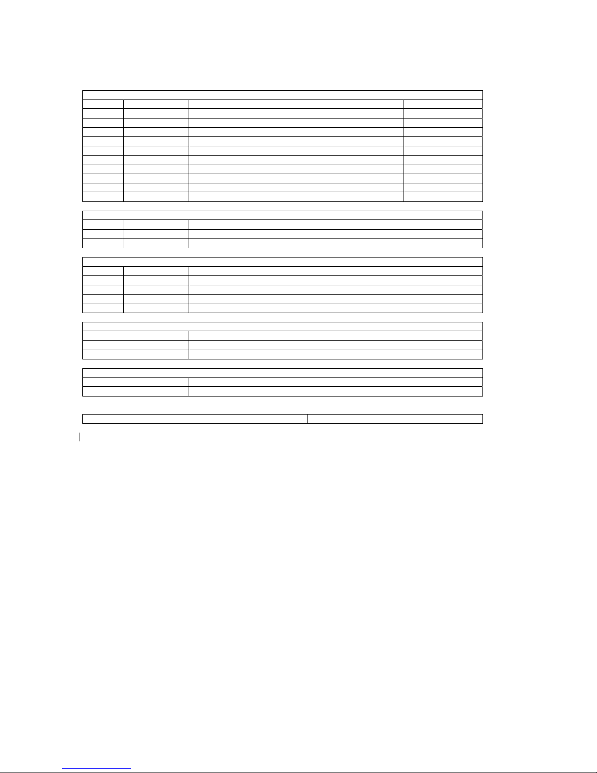
J1 Pin OEM200 Signal OEM200 Description
1 GND Ground
2 GND Ground
3 VCC Power
4 VCC Power
J1 CB – J3
(on OEM200)

5
5 GND Ground
6 PD2/RXD1/INT2
[DIG2/EXTINT2] General I/O / External interrupt
7 PC0/SPARE1 General I/O ; end node (OEM200) only
8
PE6/T3/INT6
[DIG1/RTCLK/EXTINT1] Radio Amp Indicator (Tx) – Output
9 PC1/SPARE0 General I/O ; end node (OEM200) only
10
PE5/OC3C/INT5
[DIG0/EXTINT0]
General I/O / External interrupt
11 PF1/ADC1 Analog In
12 PD1/SDA/INT1 I2C_DATA
13 PF0/ADC0 Analog In
14 PD6/T1 General I/O / Counter In
15 GND Ground
16 PE2/SCK0/AIN0 RTS
17 RESET# Atmel reset Input
18 PE3/OC3A/AIN1 CTS/16 bit PWM out
19 PF4/ADC4/TCK Module programming
20 PD0/SCL/INT0 I2C_SCK I/O
21 PF5/ADC5/TMS Module programming
22 PC2/SPARE2 General I/O ; end node (OEM200) only
23 PF7/ADC7/TDI Module programming
24 PF7_ATTEN [PIC_ICSPMCLR#] through a 10K resistor /
Carrier Board Reset Output
25 PF6/ADC6/TDO Module programming
26 PF6_ATTEN [PIC_ICSPPGM] through a 10K resistor
27 PD7/T2_ATTEN no connect (input through 10K resistor)
28 PE1/TXDO/PD0 UART TX
29 PF5_ATTEN [PIC_ICSPCLK] through a 10K resistor
30 PE0/RXD0/PDI UART RX
31 PD4/ICP1[BOOST_ENABLE] Boost Enable Request Output
32 PF4_ATTEN [PIC_ICSPDAT] through a 10K resistor
33 PD0/SCL/INT0 no connect (bit bang-able SPI)
34 PB4/OC0 Status line/ RS485 Enable
35 PD1/SDA/INT1 no connect (bit bang-able SPI)
36 PE2/SCK0/AIN0 no connect (bit bang-able SPI)
37 PE3/OC3A/AIN1 no connect (bit bang-able SPI)
38 VSUPPLY Power
39 VSUPPLY Power
40 GND Ground
41 GND Ground
J3 Pin OEM200 Signal Type OEM200 Description
1 VSUPPLY Power Power
2 GND Ground Ground

6
Functional descriptions
Power: The module is powered by a DC power source from 2.0V to 3.3V. The absolute maximum voltage that
should be applied is 3.6V. VCC and VSUPPLY are connected through a 0Ωresistor on the module. The
power plane is attached directly to VCC. J1 can carry 100mA per pin; J3 can carry 500mA per pin.
Ground: These are attached to the ground plane of the module. J1 can carry 100mA per pin; J3 can carry
500mA per pin.
General I/O: These are bidirectional, CMOS level, digital signals running between VCC and GND.
General I/O / external interrupt: These are bidirectional, CMOS level, digital signals running between VCC
and GND. They can also be configured as external, hardware interrupts.
General I/O / external interrupt / counter in: This is a bidirectional, CMOS level, digital signal running
between VCC and GND. It can be configured as external, hardware interrupt or as an input to a counter.
Analog In: These are analog inputs.
Initialization: These pins are digital inputs and outputs used during the initialization of the module.
Two-wire interface: Both SDA and SCK have 10kΩpull-ups to VCC. The module acts as the master on the
bus.
UART: Two-wire (RX/TX) or four-wire (RX/TX/CTS/RTS) logic level interface. Runs at 9600 baud, 8 data
bits, no parity, 1 stop bit.
Reset: An active low signal (RESET#) to reset the microcontroller. Used during debug and test of the module.
JTAG Programming: These provide a four wire interface into JTAG controller on the module’s
microcontroller. These are used during debug and test of the module.

7
Mechanical interface
(all dimensions in inches unless otherwise noted)
Top side module height: max 0.255”
Bottom side module height: max 0.149”
The OEM200 is a printed circuit board (PCB) assembly with two connectors (J1 and J3) and three mounting
holes. The primary interconnection is J1, the 41 position board to board, connector on the bottom of the
assembly. When loaded into its mating connector on a carrier board, the bottom of the OEM100’s PCB will
be 4.3mm (0.169 inches) from the top of that carrier board. The mounting holes are designed to accommodate
4mm tall, board to board, plastic, stacking posts also on the bottom side (e.g. Richco p/n MDLSP1-04M-01).
Alternatively, #2, nylon fasteners may be used.

8
Recommended Carrier PCB Layout
The OEM200 occupies 1.60” by 1.58” and is designed to plug into a PCB mounted, 41 position, Hirose DF9
receptacle (Hirose p/n DF9A-41S-1V(20)). Please refer to Hirose’s documentation for more information
about this connector. There are three mounting holes designed to accommodate 4mm plastic stacking posts
(Richco p/n MDLSP1-04M-01). Please note that Carrier Boards should often be designed to accommodate
multiple OEM radio boards from Sensicast. Sensicast will strive to maintain a common inter-connect across
various OEM radio boards and carrier boards, but the size of the OEM radio boards and thus the third
mounting hole and antenna locations will vary. Please contact Sensicast for more specific information and
product plans.
There are four distinct areas of the carrier board PCB:
(A) This is reserved for the OEM200’s radio signals, and this area should be kept clear of all metal
components including traces and planes. Note, this zone extended above and below the PCB.
(B) In this area there are no restrictions on component placement or height.
(C) On the top layer, components should be limited to 0.125” in height to fit below the OEM100/200.
On all other layers there are no restrictions.
(D) On the top layer, the only component should be the Hirose receptacle. On all other layers there are
no restrictions.
Product Labeling Information
Please see important FCC labeling information at the beginning of this manual.
Each module is programmed with a unique address. This address is printed on the barcode label on the back
of the module. In most applications it is helpful to reproduce this label on the outside of the final product
packaging.
1.38 0.99
0.216 landing area x3
0.104 through hole x3

9
Technical Specifications
Radio frequency 2.4GHz Frequency Hopping Spread Spectrum
Radio power +15dBm (32mW) nominal
Battery life Up to 3 years with a 2/3A Lithium battery using a 5 minute report interval (sensor
dependent)
Range Up to 1000’ (outdoors, line of sight)
Up to 230’ (typical indoor conditions)
Connector options Two (2) analog input lines
Six (6) digital I/O lines
Two-wire interface bus
UART (TX, RX, RTS and CTS)
Antenna PCB “Inverted F” antenna included
LEDs 3 diagnostic LEDs (red, yellow and green)

10
Appendix A
Developer’s Kit Adapter Board
Optionally a Sensicast Developer’s Kit Adapter Board (P/N 1408) can be used to ease prototyping with the
OEM100/200. There are .104” diameter mounting holes that correspond to the mounting holes of the
OEM100/200. The board has a Hirose receptacle that mates with the OEM100’s 41 position header. Each
signal is brought to a test point arranged on a 2mm grid.
Some of the more commonly used signals are brought to three other connectors (P1, P2 and P3) for ease of
integration with a microcontroller based target board. A multicolor ribbon cable the mates with J1 is also
provided. There is a 3.3V regulator that allows the user to power the OEM100/200 from an AC power
adapter. Here is a drawing of the adapter board and a description of the connectors and their signals
If the optional target developer’s board is being used, the I2C and jumper wires included are compatible with
P2 and P3.
11
P1 - 10 position (2x5) 0.1 inch pitch ribbon cable connector
pin Signal description Ribbon cable color
1 INT_S2R Interrupt line from sensor to radio module, active on rising edge Brown
2 INT_R2S Interrupt line from radio module to sensor, active on rising edge Red
3 SCL Two wire interface, serial clock Orange
4 SDA Two wire interface, serial data Yellow
5 TXD UART (3V logic level), radio module transmit data Green
6 RXD UART (3V logic level), radio module receive data Blue
7 RTS UART (3V logic level), radio module ready to send Violet
8 CTS UART (3V logic level), radio module clear to send Gray
9 EXT_VCC Power source for radio module (2.0V to 3.6V) White
10 GND Ground Black
P2 – 2 position 0.1 inch pitch header
pin Signal Description
1 INT_S2R Interrupt line from sensor to radio module, active on rising edge
2 INT_R2S Interrupt line from radio module to sensor, active on rising edge
P3 - 4 position (2x2) 0.1 inch pitch ribbon cable connector
pin Signal Description
1 SCL Two wire interface, serial clock
2 SDA Two wire interface, serial data
3 EXT_VCC Power source for radio module (2.0V to 3.6V)
4 GND Ground
P4 - 3 position 0.1 inch pitch jumper
Short pins Function
1 and 2 Power from on board 3.3V regulator
2 and 3 Power from P1 or P3
P5 – barrel connector jack
Outer Ground
Center +5V
P6 - 41 position Hirose DF9 receptacle (bottom) See above description of signals

12
Prediction of MPE limit at a given distance
Equation from page 18 of OET Bulletin 65, Edition 97-01
where: S = power density
P = power input to the antenna
G = power gain of the antenna in the direction of interest relative to an isotropic radiator
R = distance to the center of radiation of the antenna
Maximum peak output power at antenna input terminal: 16.00 (dBm)
Maximum peak output power at antenna input terminal: 39.811 (mW)
Antenna gain(typical): 0 (dBi)
Maximum antenna gain: 1.000 (numeric)
Prediction distance: 20 (cm)
Prediction frequency: 2400 (MHz)
MPE limit for uncontrolled exposure at prediction frequency: 1 (mW/cm^2)
Power density at prediction frequency: 0.007920 (mW/cm^2)
Maximum allowable antenna gain: 21.0 (dBi)
20 cm = 21.0 dB
Note: Only enter values in yellow boxes.
Margin of Compliance at
2
4R
PG
S
π
=
Popular Computer Hardware manuals by other brands

Digi
Digi Digi One EM Hardware reference manual

ekwb
ekwb EK-FB KIT GA P67A UD7 INSTALLATION AND MOUNTING MANUAL

Parker
Parker Dynaserv G2 user guide

Sierra Wireless
Sierra Wireless AirCard 595 reference guide

Genovation
Genovation ControlPad CP48 Getting started

National Instruments
National Instruments NI 78xxR Getting started guide


National Instruments
National Instruments NI TB-2636 installation instructions

Freescale Semiconductor
Freescale Semiconductor USB-KW24D512 quick start guide

SeaLevel
SeaLevel SeaLINK +2.SC user manual

SeaLevel
SeaLevel PIO-48 4030 user manual

TDK
TDK HHM Series HHM1521 Specifications

SIIG
SIIG USB 2.0 Bay Reader/Writer+Floppy Quick installation guide