manuals.online logo
Brands
  1. Home
  2. •
  3. Brands
  4. •
  5. AMX
  6. •
  7. Computer Hardware
  8. •
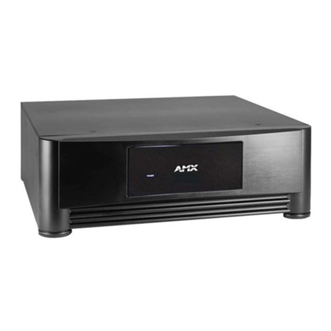
  9. AMX FG1052-13 User manual

AMX FG1052-13 User manual

This manual suits for next models

5

Other AMX Computer Hardware manuals

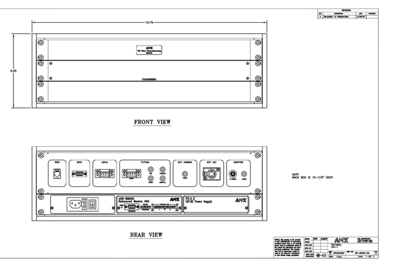
AMX VTX-1 Quick start guide

AMX

AMX VTX-1 Quick start guide

AMX KC/2R Quick start guide

AMX

AMX KC/2R Quick start guide

AMX HD-15 User manual

AMX

AMX HD-15 User manual

AMX AXD-MSP8 Quick start guide

AMX

AMX AXD-MSP8 Quick start guide

AMX RTS1 Quick start guide

AMX

AMX RTS1 Quick start guide

AMX Enova AVS-ENOVADGX32-VO-HDMI User manual

AMX

AMX Enova AVS-ENOVADGX32-VO-HDMI User manual

AMX TP4-RGB Quick start guide

AMX

AMX TP4-RGB Quick start guide

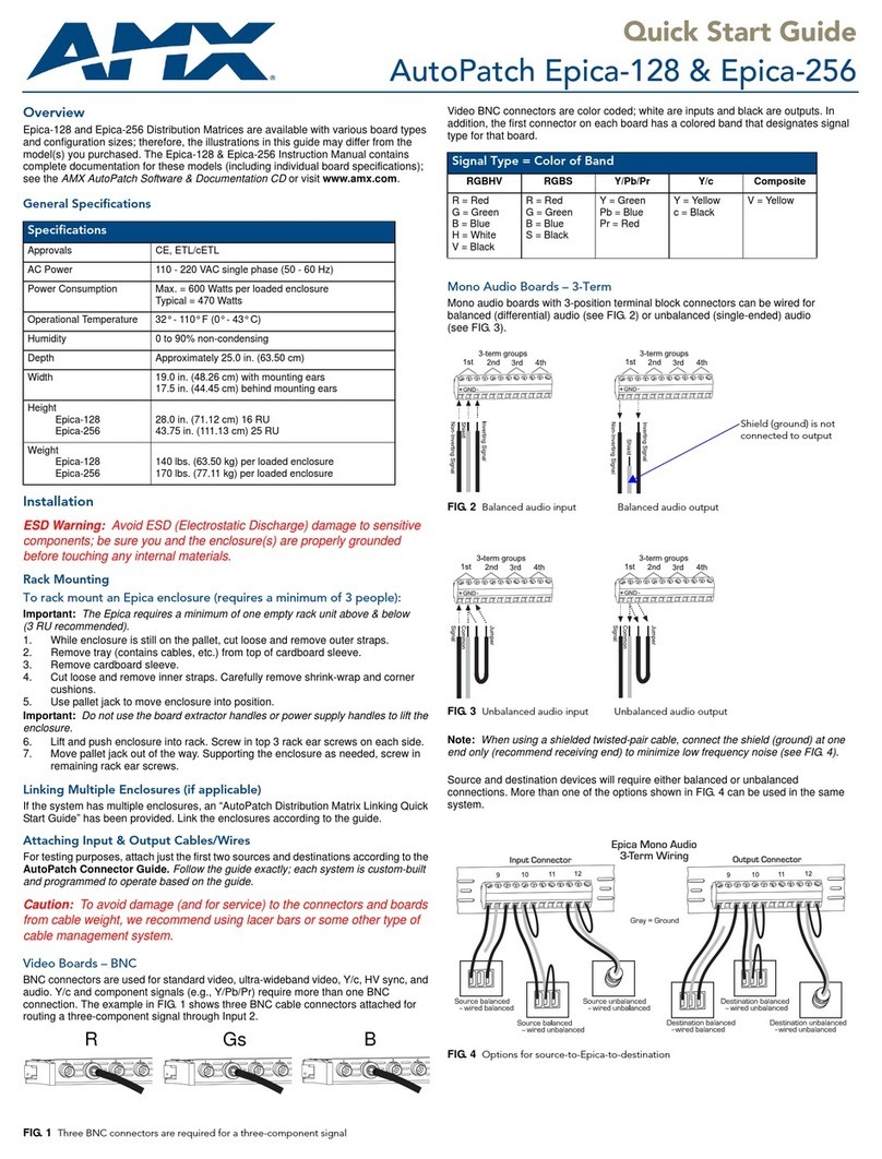
AMX AutoPatch Epica-128 User manual

AMX

AMX AutoPatch Epica-128 User manual

AMX UPC20 Quick start guide

AMX

AMX UPC20 Quick start guide

AMX AXU-CA10 User manual

AMX

AMX AXU-CA10 User manual

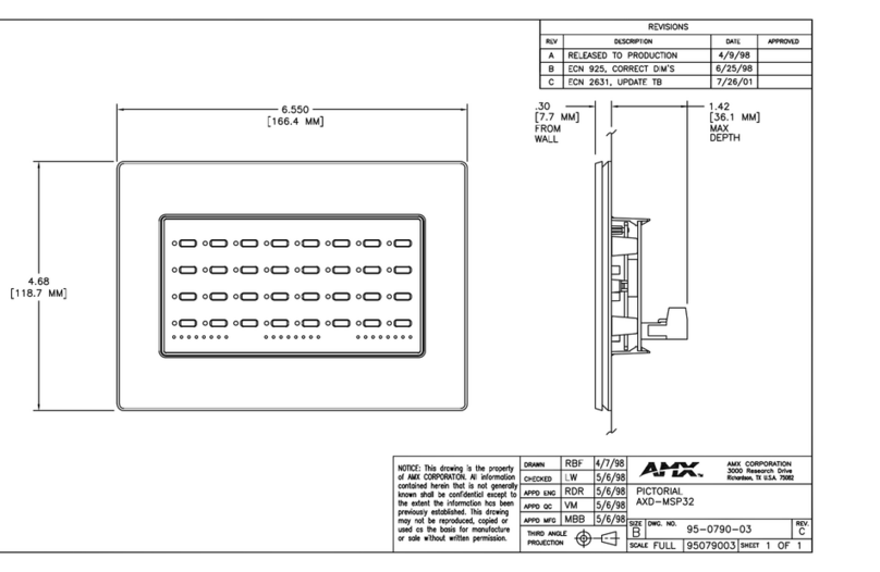
AMX AXU-MSP32 Quick start guide

AMX

AMX AXU-MSP32 Quick start guide

AMX NMX-WP-N1512 User manual

AMX

AMX NMX-WP-N1512 User manual

AMX RDD-DM4/277 Quick start guide

AMX

AMX RDD-DM4/277 Quick start guide

AMX Multi-Disc Loader System MAX MDL200 User manual

AMX

AMX Multi-Disc Loader System MAX MDL200 User manual

AMX AXM-CA10 Quick start guide

AMX

AMX AXM-CA10 Quick start guide

AMX AXU-SPL4 Quick start guide

AMX

AMX AXU-SPL4 Quick start guide

AMX PLB-CF10 User manual

AMX

AMX PLB-CF10 User manual

AMX RDC-DC/240 Quick start guide

AMX

AMX RDC-DC/240 Quick start guide

AMX RDM-2DC Quick start guide

AMX

AMX RDM-2DC Quick start guide

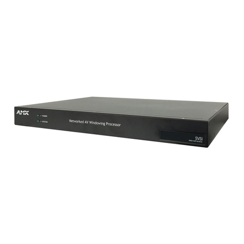
AMX FG1052-13 User manual

AMX

AMX FG1052-13 User manual

AMX AXU-MSP8 Quick start guide

AMX

AMX AXU-MSP8 Quick start guide

AMX NetLinx Master-Ethernet Card/Module... Guide

AMX

AMX NetLinx Master-Ethernet Card/Module... Guide

AMX AXU-MSP24 Quick start guide

AMX

AMX AXU-MSP24 Quick start guide

AMX AXM-MSP32 Quick start guide

AMX

AMX AXM-MSP32 Quick start guide

Popular Computer Hardware manuals by other brands

Toshiba TOSVERT VF-MB1/S15 IPE002Z Function manual

Toshiba

Toshiba TOSVERT VF-MB1/S15 IPE002Z Function manual

Shenzhen MEITRACK MVT380 user guide

Shenzhen

Shenzhen MEITRACK MVT380 user guide

TRENDnet TEW-601PC - SUPER G MIMO WRLS PC CARD user guide

TRENDnet

TRENDnet TEW-601PC - SUPER G MIMO WRLS PC CARD user guide

StarTech.com CF2IDE18 instruction manual

StarTech.com

StarTech.com CF2IDE18 instruction manual

Texas Instruments LMH0318 Programmer's guide

Texas Instruments

Texas Instruments LMH0318 Programmer's guide

Gateway 8510946 user guide

Gateway

Gateway 8510946 user guide

Devon IT TC2D Quick setup guide

Devon IT

Devon IT TC2D Quick setup guide

Krüger & Matz Air Shair2 owner's manual

Krüger & Matz

Krüger & Matz Air Shair2 owner's manual

Crystalio VPS-2300 quick guide

Crystalio

Crystalio VPS-2300 quick guide

MYiR FZ3 user manual

MYiR

MYiR FZ3 user manual

Protech Systems BC-K200 Quick reference guide

Protech Systems

Protech Systems BC-K200 Quick reference guide

Miranda DENSITE series DAP-1781 Guide to installation and operation

Miranda

Miranda DENSITE series DAP-1781 Guide to installation and operation

Sierra Wireless Sierra Wireless AirCard 890 quick start guide

Sierra Wireless

Sierra Wireless Sierra Wireless AirCard 890 quick start guide

Leadtek Killer Xeno Pro Quick installation guide

Leadtek

Leadtek Killer Xeno Pro Quick installation guide

Star Cooperation FlexTiny 3 Series Instructions for use

Star Cooperation

Star Cooperation FlexTiny 3 Series Instructions for use

Hotone Ampero user manual

Hotone

Hotone Ampero user manual

Connect Tech Xtreme/104-Express user manual

Connect Tech

Connect Tech Xtreme/104-Express user manual

Yealink WF50 user guide

Yealink

Yealink WF50 user guide

manuals.online logo
manuals.online logoBrands
  • About & Mission
  • Contact us
  • Privacy Policy
  • Terms and Conditions

Copyright 2025 Manuals.Online. All Rights Reserved.

Quick Start Guide
AutoPatch Component Video (BNC & RCA) DAD Modules
Overview
Component Video Distribution Amplifier Driver (DAD) Modules are available with
BNC or RCA connectors. The modules have either one input and two outputs for
1:2 distribution or one input and six outputs for 1:6 distribution of component video
signals. The single component video input is distributed to two or six outputs over
standard cable runs of up to 500 ft. (152.4 m) for YPbPr and up to 250 ft. (76.20 m) for
RGB with no additional equipment required. Each output can be independently
adjusted for gain and peaking to ensure the proper amount of compensation is
provided for each cable run. This guide contains complete information for this product.
Product Specifications
* The Component Video 1:2 DAD module uses a power supply that is provided with
the unit.
** Gain and Peaking are independent switches that allow the user to turn on or off the
gain and peaking.
Installation
Mounting Options
1:2 Models
Desktop – Attach the rubber feet (included) to the bottom of the module.
V Style Rack Mounting – Mounting brackets and rack trays are available for these
versatile modules (contact your AMX representative).
1:6 Models
Desktop – Attach the rubber feet (included) to the bottom of the module.
Rack Mounting
To rack mount a 1:6 module:
1. Remove one screw from each side of DAD (FIG. 3) Do not reuse for rack ear.
2. Attach the rack ears as shown in FIG. 3 (screws provided).
3. Place the module in a standard EIA 19 in. (48.26 cm) rack and secure it to rack
with screws.
FIG. 1 Component Video DADs, 1:2 models
FIG. 2 Component Video DADs, 1:6 models
General Specifications
Approvals Pending
Power* 1:2 model
Consumption (max.)
Consumption (typical)
Connector
Power 1:6 model
Consumption (max.)
Consumption (typical)
+12 VDC to +24 VDC, 1A
+12 VDC, 400 mA
2.1 mm DC power jack
100 to 240 VAC single phase, 50 - 60 Hz
120 VAC, 650 mA
120 VAC, 100 mA
Operational Temperature 32° to 110° F (0° to 43° C)
Humidity 0 to 90% non-condensing
Dimensions 1:2 model 5.15 in. (13.08 cm) depth
4.35 in. (10.92 cm) width
1.66 in. (4.22 cm) height without feet, 1 RU on rack shelf
Approximately 1.3 lb. (0.6 kg) weight
Dimensions 1:6 model 5.15 in. (13.08 cm) depth
17.40 in. (44.20 cm) width without rack ears
19.00 in. (48.26 cm) with ears
1.72 in. (4.37 cm) 1 RU height without feet
Approximately 4.5 lb. (2 kg) weight
Connector Type BNC, RCA
RGB & YPbPr Signal Specifications
Frequency Response ±3 dB, 450 MHz or better
Signal to Noise Ratio Vin = 0.7 V, 100% IRE >65 dB
Level
Input (max.)
Output (max.)
±1.75 V
±1.75 V
Impedance
Input
Output
75 ohms
75 ohms
Return Loss -45 dB @ 5 MHz
Connector Type BNC, RCA
RGB (BNC) Model FG1052-25 YPbPr (RCA) Model FG1052-19
YPbPr (RCA) Model FG1052-22
RGB (BNC) Model FG1052-28
RGBRGB
RGBRGBRGB
RGB Gain & Peaking** Specifications
Gain
OFF
ON
Unity
+0.85 dB
Peaking
OFF
ON
No peaking
8 dB @ 150 MHz
8 dB @ 300 MHz
Cable Length (max.) 250 ft. (76.20 m)
YPbPr Gain & Peaking** Specifications
Gain
OFF
ON
Unity
+0.85 dB
Peaking
OFF
ON
No peaking
9 dB @ 37.5 MHz
9 dB @ 80 MHz
Cable Length (max.) 500 ft. (152.4 m)
FIG. 3 Remove screw (do not re-use) & attach rack ears
Remove screw
For full warranty information, refer to www.amx.com
12/07
©2007 AMX. All rights reserved. AMX and the AMX logo are registered trademarks of AMX.
AMX reserves the right to alter specifications without notice at any time.
3000 RESEARCH DRIVE, RICHARDSON, TX 75082 • 800.222.0193 • fax 469.624.7153 • technical support 800.932.6993 • www.amx.com
93-1052-01 REV: A
Typical Setup
Attaching Input & Output Cables
To attach connectors (1:2 models):
1. Fasten the BNC or RCA connectors from source and destination devices onto
BNC or RCA connectors on module (FIG. 5 shows RCA connectors).
2. Plug the desktop power supply into the power jack on the module and into an
external AC power source.
3. Apply power to the source and destination devices.
4. Adjust DIP switches on front if necessary (FIG. 7 in right column).
Note: The power indicator LED is on the module’s front.
To attach connectors (1:6 models) :
1. Fasten the BNC or RCA connectors from source and destination devices onto
BNC or RCA connectors on module (FIG. 6 shows BNC connectors).
2. Attach the power cord into the power receptacle on the module and into an
external AC power source.
3. Press the “I” side of the power switch.
4. Apply power to the source and destination devices.
Note: The power indicator LED is on the module’s front.
Front Panel DIP Switches
Each DIP switch pair controls the output gain and peak of the same-numbered
output signal. The default setting is both switches “Off” (down, FIG. 7), which
represents unity gain and no peaking. The gain and peak adjustments can
compensate for long cable runs. To increase brightness of a destination’s video, set
the gain DIP switch to “On”. To sharpen a destination’s video, set the peak DIP
switch to “On”.
To adjust DIP switches:
1. Using a small screwdriver or paper clip, flip the toggles on the DIP switches up
(see table below FIG. 7 for settings).
Flip either or both switches “ON” depending on the length of the cable run.
FIG. 4 Typical system setup using 1:2 DA
FIG. 5 Attach input and output connectors (model with RCA connectors shown)
FIG. 6 Attach input and output connectors (model with BNC connectors shown)
DVD
Source device
Destination devices
1:2 DAD module
Power
RCAs
From source To destinations
RGBRGB
RGBRGBRGB
From To destinations
Power
BNCs
source
FIG. 7 Adjust DIP switches for gain and peaking
DIP Switch Settings – RGB (BNC)
OFF (default) ON Result
Gain Unity gain +0.85 dB Brightens image
Peaking No peaking 8 dB @ 150 MHz
8 dB @ 300 MHz Sharpens image
DIP Switch Settings – YPbPr (RCA)
OFF (default) ON Result
Gain Unity gain +0.85 dB Brightens image
Peaking No peaking 9 dB @ 37.5 MHz
9 dB @ 80 MHz Sharpens image
Example:
Outputs 2, 3, & 6 are set to ON for gain & peaking
Outputs 1, 4 & 5 are set to OFF / unity