SENSIRION EK-F3 Series User manual

Evaluation-Kit EK-F3(_L;_R;_V)
Gas Mass Flow Meter EM1
Version 2.0
Table of Contents
_ Introduction
_ What You Need to Get Started
_ Installing the Hardware
_ General Measurement Setup
_ Installing the Software and Start-Up
_ Software Overview Flow Viewer
_ Disclaimer
www.sensirion.com Sensirion AG, Laubisrütistrasse 50, CH-8712 Stäfa ZH, Switzerland, Tel: +41 1 306 40 00, Fax: +41 1 306 40 30
EK-F3 Evaluation Kit
Introduction
The CMOSensEcoLine EM1 Mass Flow Meter (MFM) enables fast and economical measurement of gas
flows over a very wide dynamic range. Its leading price/performance ratio is based on Sensirion’s unsur-
passed CMOSenssensor technology which combines a sensor element with the amplification and A/D
converter circuit on one single CMOS chip. This results in very good performance, fast response time and
large dynamic range at very attractive cost.
The EM1 evaluation kit EK-F3 offers an easy-to-use environment to illustrate the unique features of the
sensor system and to adapt it to your specific application. The contents of the kit are listed below (see
Figure 1 and Table 1). It includes one EM1 meter, a serial interface cable, various standard fittings for an
easy flow connection, and a Viewer Software to make the measurement results visible on a PC.
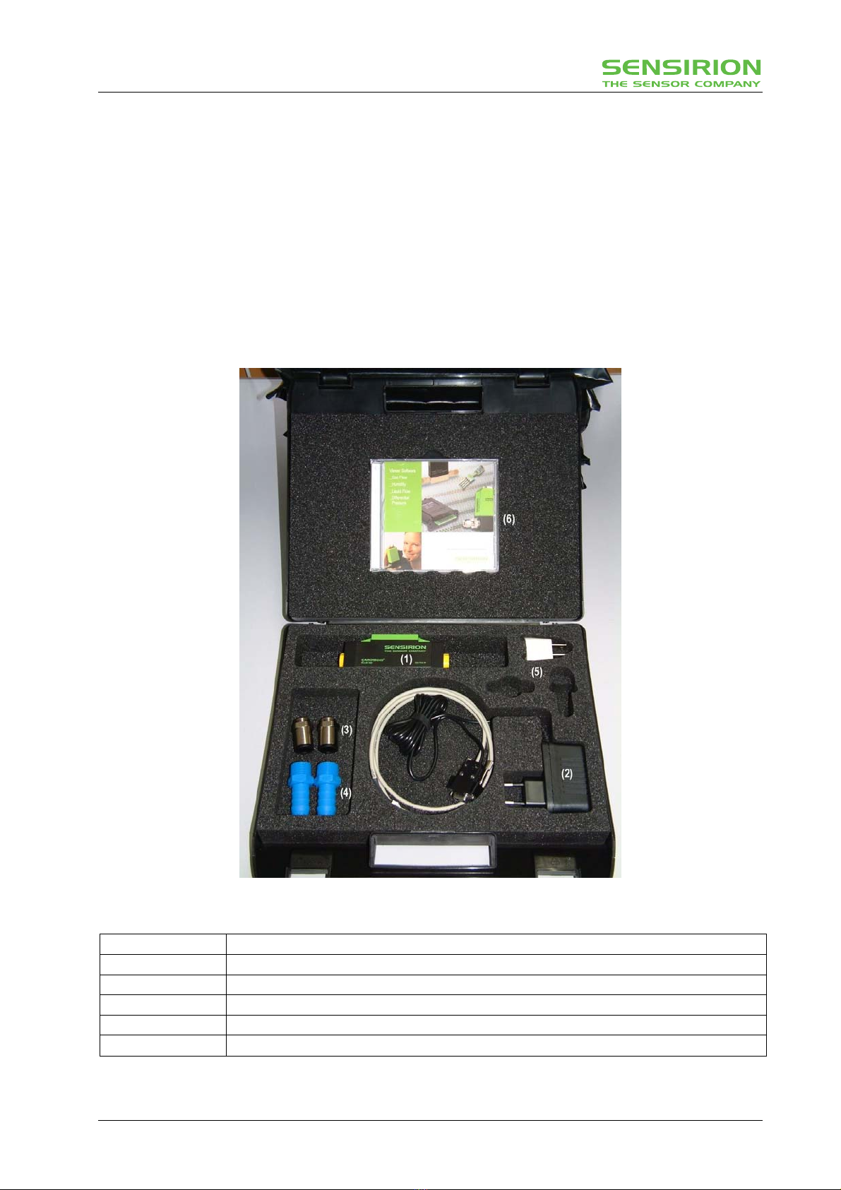
Figure 1: Photograph of the evaluation kit with its contents
(1) Mass Flow Meter EM1
(2) Serial interface cable (Sub-D 9pin) with power supply (Euro-Connector)
(3) Legris Flow Connector (No. 3101 1217 ; G3/8; Tube OD=12mm)
(4) Hausamann Flow Connector (No. 38.131; G3/8; Tube ID=10mm)
(5) Power Adapter for US-style plugs
(6) FlowViewer software on CD
Table 1: Contents of the evaluation kit EK-F3
www.sensirion.com Page 2 of 7
EK-F3 Evaluation Kit
What You Need to Get Started
Make sure you have all of the following items before you install the hardware and FlowViewer software for
Windows 95/98/NT/2000/XP:
_ Windows 95/98/2000/NT/XP
_ An unused serial interface port (e.g. COM1).
_ FlowViewer software for Windows 95/98/NT/2000/XP on CD.
_ Contents of your evaluation kit as described in the Introduction.
Additionally, software for the use of your EM1 with a PDA using Palm OS is available on our internet page
(www.sensirion.com).
Installing the Hardware
In the following section all the necessary electrical interconnections for the EM1 sensor system will be
listed. These connections are required between the EM1, a PC serial interface and a power supply.
To install your EM1 complete the following steps (see Figure 2):
1. Turn off your PC. Keep your PC plugged in so that it remains grounded while you install the EM1.
2. Connect the serial interface cable with the COM port of your PC (configuration of the serial interface
see datasheet EM1).
3. Turn on your PC and start Windows 95/98/2000/NT/XP.
4. Connect the interface cable with the EM1 (see also pin diagram of the EM1 given in datasheet EM1).
5. Plug in the power supply. Input 100V - 240V AC, 47Hz - 63Hz.
The EM1 is now connected with your PC and ready to use. Proceed to the next section for a general
measurement setup. For further information on connecting the EM1 please refer to the datasheet.
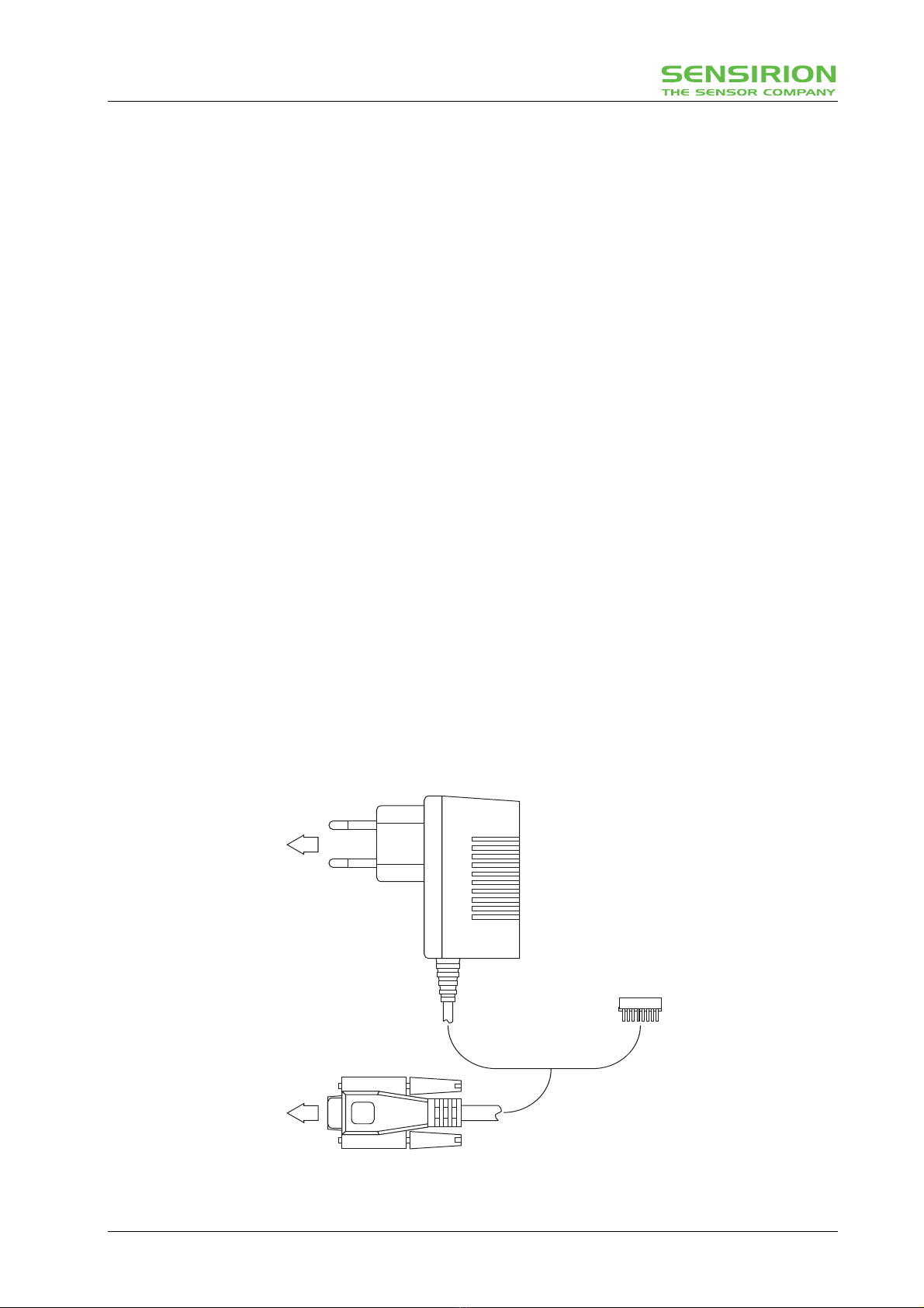
to Power Line
to COM Port
Connector
Serial Interface Connector
Interface Cable
Power Supply
to EM1
Figure 2: General measurement setup for the EM1 Mass Flow Meter system. For detailed link of the
sensor system to a gas supply please refer to the next section.
www.sensirion.com Page 3 of 7

EK-F3 Evaluation Kit
General Measurement Setup
Once the hardware installation has been completed, a gas flow has to be applied to the EM1.
In order to couple a gas flow to the EM1 meter you can either use the flow connectors included in the EK-
F3 kit or any other connectors with G3/8 thread.
The Legris connectors included can be used for hoses of 12 mm outer diameter, the Hausamann connec-
tors included in the EK-F3 kit can be used for hoses of 10 mm inner diameter. Additional connectors which
can be used are listed in the data sheet.
Since the EM1 meter is a unidirectional flow meter please observe the flow direction when connecting the
EM1 device. The flow is indicated by arrows on the top cover of the meter (please see Figure 3 for details).
Figure 3: Indication of the flow direction on the EM1 device. Also the pin layout is shown
Installing the Software and Start-Up
After having installed the EM1 hardware, complete the following steps to install the FlowViewer software for
Windows 95/98/2000/NT/XP on your PC:
1. Insert the CD with the FlowViewer software for Windows 95/98/2000/NT/XP.
2. Open the file "DISKS", double-click "SETUP.EXE" and follow the instructions of the installation wiz-
ard.
3. Start with Start -> Programme -> Sensirion AG -> Sensiview_v2_2 or through the path where you in-
stalled the software.
4. Note: If no units are displayed in the program it may be possible your decimal symbol in the "Regional
Setting Properties" of the Windows operating system is wrong.
For a detailed description on FlowViewer please refer to next section.
Please note: This software is protected and intended exclusively for demonstration and laboratory purposes. It may not be used
or multiplied commercially. SENSIRION does not offer any guarantee.
Software Overview FlowViewer
In order to operate the EM1, dedicated software is provided with your evaluation kit. Although the software
allows plug-and-play, some additional remarks will be given.
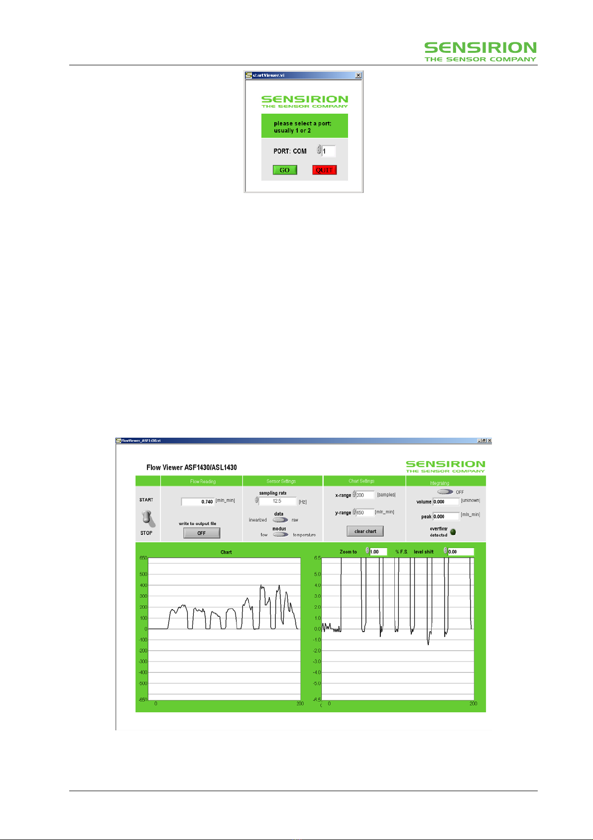
To start the FlowViewer, double click its icon. A pop-up window will appear which guides you to a proper
setting of your COM port with the connected EM1 (see Figure 4). In case the EM1 cannot be linked to the
FlowViewer please check all your connections between the sensor and your system. Make also sure that
the COM port chosen is not used by any other application already running in the background (i.e. Palm
Hotsync etc.)
www.sensirion.com Page 4 of 7
EK-F3 Evaluation Kit
Figure 4: Pop-up window for proper connection of the EM1 to the FlowViewer 2.2
Once the connection has been set up, the FlowViewer main window will appear (see Figure 5), allowing
mass flow to be displayed. Measurements are started with the START button and interrupted with the
STOP button.
You will notice that the EM1 is displayed as ASF1430/ASL1430.The reason for this is that the EM1 uses
the same software in its microprocessor as the ASF/ASL1430 series.
The different full scale versions of the EM1 (500 mln/min, 20’000 mln/min = 20 ln/min and 200 ln/min) can
be recognized by the values of the y-axis on the left side graph and the given unit in the “Flow Reading”
section. Samples for each version are shown in Figure 5 to Figure 7.
In the section “Sensor Settings” the sampling rate, data format and modus can be set. Depending on power
supply and heat dissipation the sensor temperature can be a few degrees above room temperature.
The section “Chart Setting” allows you to configure the graphs. If “Integrating” is on, information about ac-
cumulated volume and peak flow is displayed.
The left side shows the full meter range and the right side shows a selectable zoom area. The zoom factor
and the level shift can be set by the selectors above the graph.
Figure 5: FlowViewer displaying measurement data of the EM1_L (500 mln/min)
www.sensirion.com Page 5 of 7
EK-F3 Evaluation Kit
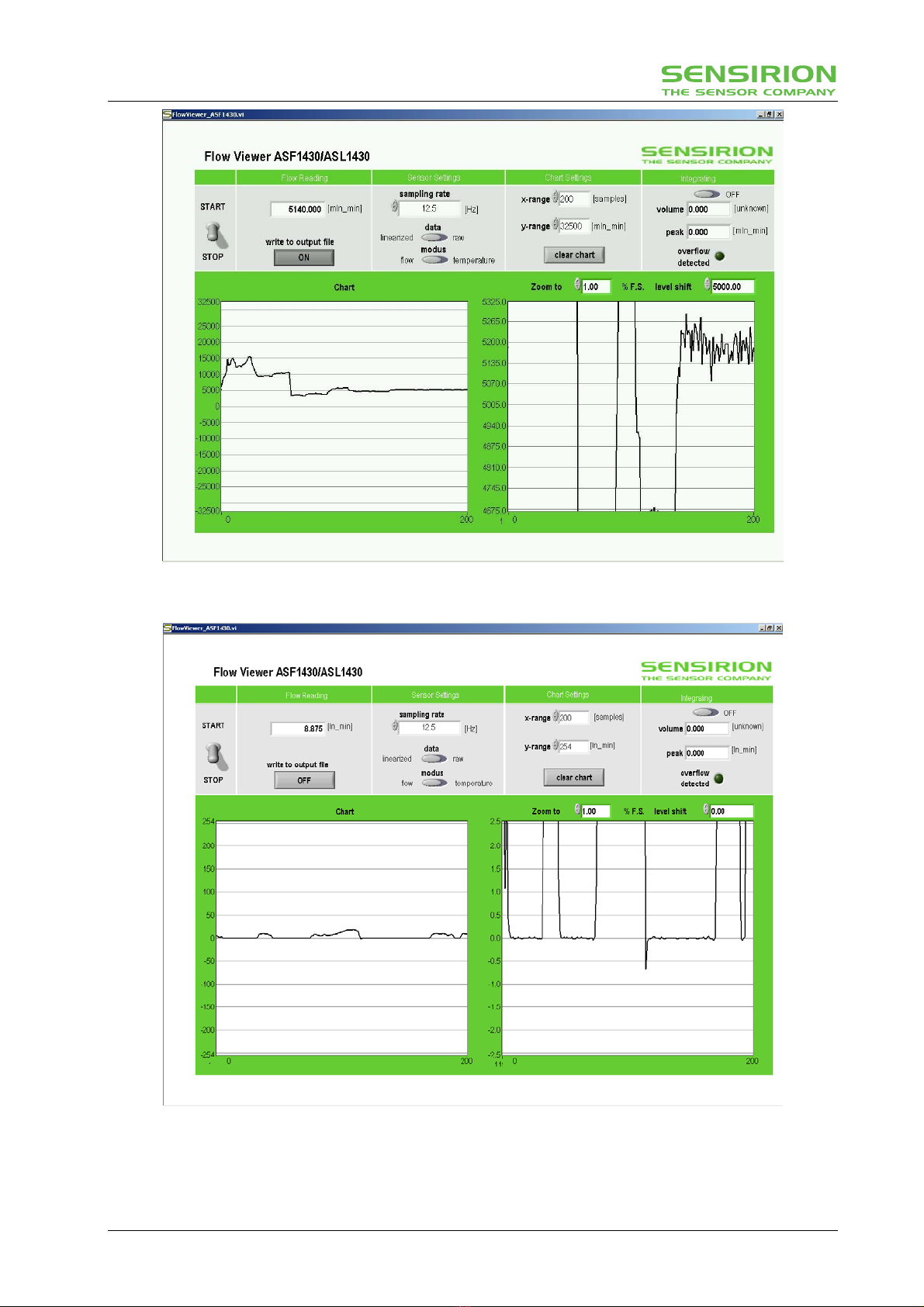
Figure 6: FlowViewer displaying measurement data of the EM1_R (20’000 mln/min = 20 ln/min)
Figure 7: FlowViewer displaying measurement data of the EM_V (200 ln/min)
www.sensirion.com Page 6 of 7
EK-F3 Evaluation Kit
Important Notices
Warning, personal injury
Do not use this product as safety or emergency
stop devices or in any other application where
failure of the product could result in personal
injury. Failure to comply with these instructions
could result in death or serious injury.
Should buyer purchase or use SENSIRION AG products for any such
unintended or unauthorized application, Buyer shall indemnify and hold
SENSIRION AG and its officers, employees, subsidaries, affiliates and
distributors harmless against all claims, costs, damages and expenses,
and reasonable attorney fees arising out of, directly or indirectly, any claim
of presonal injury or death associated with such unintended or unauthor-
ized use, een if such claim alleges that SENSIRION AG was negligent
regarding the design or manufacture of the part.
ESD Precautions
The CMOSensEcoLine Mass Flow Meter is an
electronic device. For this reason Sensirion recom-
mends to use standard ESD (electrostatic discharge)
precautions when handling this device.
Warranty
SENSIRION AG makes no warranty, representation
or guarantee regarding the suitability of its product for
any particular purpose, nor does SENSIRION AG
assume any liability arising out of the application or
use of any product or circuit and specifically disclaims
any and all liability, including without limitation conse-
quential or incidental damages. “Typical” parameters
can and do vary in different applications. All operating
parameters, including “Typical” must be validated for
each customer applications by customer’s technical
experts.
SENSIRION AG reserves the right, without further
notice, to change the product specifications and/or
information in this document and to improve reliability,
functions and design.
CMOSensis a trademark of Sensirion. SPI is a
trademark of Motorola.
Copyright 2003 - 2005, Sensirion AG. All rights re-
served.
FCC and CE Statement
The CMOSensEcoLine MFM product has been
tested and found to comply with the limits for a Class
B digital device, pursuant to part 15 of the FCC Rules
(FCC CFR 47). These limits are designed to provide
reasonable protection against harmful interference in
a residential installation. This equipment generates,
uses and can radiate radio frequency energy and, if
not installed and used in accordance with the instruc-
tions, may cause harmful interference to radio com-
munications. However, there is no guarantee that
interference will not occur in a particular installation. If
this equipment does cause harmful interference to
radio or television reception, which can be determined
by turning the equipment off and on, the user is en-
couraged to try to correct the interference by one of
more of the following measures:
• Reorient or relocate the receiving antenna.
• Increase the separation between the equip-
ment and the receiver
• Connect the equipment into an outlet on a
circuit different from that to which the re-
ceiver is connected.
• Consult a dealer or an experienced radio/TV
technician for help.
The CMOSensEcoLine device fully complies with
norm EN 61000-6-1 to EN 61000-6-4 (Immunity and
Emission Test Series).
Headquarters and Sales Office
Sensirion AG Phone: + 41 (0)1 306 40 00
Laubisrütistrasse 50 Fax: + 41 (0)1 306 40 30
CH-8712 Stäfa ZH e-mail: info@sensirion.com
Switzerland http://www.sensirion.com/
www.sensirion.com Page 7 of 7
Table of contents
Other SENSIRION Motherboard manuals


