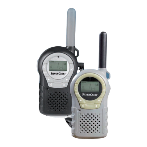
SFE SD618 Series User manual

SD618 Series
SFE Electronic Technology Co.,Ltd
35 Yangming Rd.,Qianyang Industrial Zone,Shuangyang
Loujiang,Quanzhou,Fujian,China


1 Safety Information ................................................1
2 Supplied Accessories ........................................2
3 Getting Acquainted .............................................3
■Radio Diagram ..................................................... 3
4 Battery Information ..........................................4-5
■Caution .................................................................. 4
■Battery Charging ................................................... 5
5 Accessories Installation ................................. 6-9
■Installing/Removing the Battery Pack .................... 6
■Installing/Removing the Antenna ........................ 8
■Installing/Removing the Belt Clip ........................ 8
■Installing an Earpiece ............................................. 9
6 Basic Operations ..........................................10-11
■Power ON/OFF ..................................................... 10
■Channel Selection ............................................... 10
■Volume Adjustment .............................................. 10
■LED Torch ....................................................... 10
■Emergency Alert ................................................. 11
■Receiving ............................................................ 11
■Transmitting ...................................................... 11
7 Key Assignment .............................................12-13
8 Function and Operation ................................14-15
■Basic Settings .................................................... 14
.....................................................................14
................................................14
....................................................14
...........................................................14
Radio ID
Languages Selection
SQ(Squelch Level)
Battery Save
Time Out Timer(TOT) ................................................14
■Alert Tone Settings ..............................................14
........................................................14
..................................................14
............................................................15
................................................15
Power ON Tone
Lower Battery Alert
Keypod Tone
Digital Calling Tone
Channel Voice Prompt Tone .................................15
■Channel Information ............................................15
Zone Name ...............................................................15
Channel Name ............................................................15
■General Part ............................................................15
......................................................15
..........................................................15
RX/TX Frequency
Working Mode
Output Power ............................................................15
■Transmitting Limit ...............................................15
Always Allow ...................... ...................................15
Channel Free .............................................................15
Contents Contents

Contents Contents
Color Code Match .....................................................15
Bandwidth ................................................15
Only RX ....................................................15
............................................16■Digital Part
RX CC:
: ................................................16
........................................................16
..................................................16
........................................16
............................................16
............................................16
TX CC
TX Contactt
Dual Capacity Direct Mode
RX Group List
Voice Encryption
Time Slot Selection ............................................16
............................................17
................................................17
............................................17
..........................................17
■Analog Part
RX/TX Sub-tone Type
■Digital Contact
■RX Group List
■Scan List ...............................................17
9 Troubleshooting and Maintenance..................18
■Troubleshooting .................................................18
■Maintenance and Cleaning:...............................18
10 Specifications …........................................19-20
11 Sub-tone Tables ............................................21
12 Warranty andService ...................................22

Please read the following information carefully to become familiar
with your new SFE two-way radio SD618:
Do not attempt to repair, disassemble or re-assemble the radio.
Repair should only be carried out by a qualified Radio Engineer.
In order to avoid electromagnetic interference, please turn off the
radio in any areas where radio transmissions are not permitted e.g.
Hospitals, Aircraft, etc.
Do not place a radio in any area over, or in the deployment area of
an Air Bag within a vehicle.
Never operate the radio in potentially flammable and explosive
atmospheres.
Never replace or charge batteries in potentially flammable and
explosive atmospheres.
Do not operate the radio if its antenna is damaged.
Do not expose the radio too long periods of direct sunlight, for
example on the dashboard of a vehicle or close to heating appliances.
When using your radio, try to keep it vertical and at a distance of
5~10cm from your mouth.
Keep a distance of at least 2.5cm between the antenna and your
head and body when transmitting.
Do not place a radio in any area,such as in dusty,wet places or
uneven surfaces.
ITEM QUANTITY
SD618 Two-way Radio x1
Li-Ion Battery x1
AC Adaptor x1
Intelligent Charger Pod (optional) x1
Antenna x1
Wrist Strap x1
Belt Clip x1
User Manual x1
1 2

(1) PTT(Transmit Button)
(2) Side Key(Programmable Function)
(3) Speaker
(4) “ ” “ ” Channel Switch
(5) Microphone
(6) Led Torch Switch
(7) Antenna
(8) Light&Charging Indicator
(9) Status Indicator
(10) Power ON/OFF Knob
(11) Headset Cover
(12) Headset Jack
(13) Mini USB Jack
(14) Handstrap Hole
(15) Belt Clip
(16) Battery Cover
(17) Battery Push Button
1
3
4
5
6
11
17
16
15
14
2
9
10
12
13
7
8
Getting AcquaintedGetting Acquainted Battery Information
Li-ion battery packs and flammable objects. Mishandling may cause
the battery to rupture producing flames or extreme heat. Please take
note of the following precautions.
● In order to avoid damage to the battery, only use the charger provided.
The supplied charger is an intelligent charger and has automatic
overload-protect functions built in.
●The optimal charging temperature is between 10°C and 35°C.
Whencharging in temperatures below 10°C there may be a leakage
of electrolyte which will damage the battery. If charging above 35°C,
battery performance will be reduced.
●Do not recharge the battery pack if it is already fully charged as
this will cause damage and shorten the life of the battery.
●Do not short-circuit the battery pack or dispose of in a fire.
Never attempt to remove the casing from the battery pack.
●Do not immerse the battery in water or allow it to get wet by other
means.
Caution:
Radio Diagram
3 4

Battery Information Accessories Installation
Figure 1
1. If the Red LED flashes and the radio sound a beep every 30s after
install the battery into radio, that means the battery is low. Please use
the AC Adaptor supplied to charge the battery. Connect the AC adaptor
to the USB Jack. (See Figure 1)
2. Please use the intelligent Charger Pod optional accessory to charge
the battery. Connect the Ac adaptor to the charger pod. Place the
battery into the charger(check the battery is properly in place).
(See Figure 2)
The red LED will begin to flash – indicating that charging is in progress.
The LED will turn green when the battery is fully charged.
Note: When radio is in charging status, TX is inhibited.
Battery Charging Installing/Removing the Battery Pack
Make sure the radio is turned off. Hold the top of radio body, push
the battery button with finger along with the direction shown as ,
lift the battery cover, and remove it from behind. (See Figure 3)
Figure 2
Figure 3
Figure 4
①
OPEN
①
Place the rechargeable battery pack onto the back of the radio
making sure the tabs are located correctly in the bottom of the
radio and the battery retention catch is fully open (It will only fit in
one way). Press the battery pack firmly against the radio body and
close the battery retention catch clicking it firmly into place.
(See Figure 4)
5 6
AC 110~220V
DC 5V
Charging Indicator
Battery
Mini USB
1. Power Input: DC 5V.
2. Charging Current: 500mA.
3. Protection for over-voltage,
over-charge, short-circuit.

Installing/Removing the Antenna
Screw the antenna into the connector on the top of the radio by
holding the antenna at its base and turning it clockwise until it is
secure. (See Figure 7)
To remove the antenna, hold the antenna at its base and turn it
counter-clockwise until it is released from the thread.
Note: S618PMR version is with fixed antenna, so if this is a S618PMR
radio, the antenna is not allowed to installed or removed, please noted!
To remove the battery pack, pull open the battery retention catch and
lift the battery pack from the body of the radio. (See Figure 6)
Accessories Installation
Figure 7
Installing/Removing the Belt Clip
Hold the Belt Clip to the back of radio taking care to line up the holes,
insert the belt clip retention screws and tighten with a screwdriver.
(See Figure 8)
To remove the Belt Clip, unscrew the screws (anti-clockwise) with a
screwdriver and remove the belt clip.
OPEN
①
②
Accessories Installation
Figure 5
Figure 6
Snap the battery pack into place until you heard a click. Check that the
battery pack fits tightly in place against the body of the radio.
(See Figure 5)
7 8

Figure 8
Figure 9
Accessories Installation
Installing an Earpiece
Turn the radio OFF. Open the Speaker/microphone plastic cover with
your fingernail, and then insert the speaker/microphone plug into the
SP/MIC jacks making sure it is all the way home, then turn the radio
on. Remember to turn off the radio before removing the Earpiece.
(See Figure 9)
9 10
LED Torch
Press the LED Torch Switch, LED lights, press again to close it.
Press the LED Torch Switch for 3seconds, the LED will flash, press
again to close it.
Press the channel button to select the required
channel. The current channel number will be
heard.
Volume Adjustment
Rotate the Volume knob to adjust the volume, clockwise to increase
the volume and counter-clockwise to decrease it.
If your dealer programmed Monitor onto side key, you can press
Monitor key to hear background noise while adjusting the volume
level.

Emergency Alert
To activate the emergency alert, in standby status, long press the
side key which programmed as “Emergency Alert” for 3 seconds
until the radio emits alarm to your partner or systern. Repreat the
above steps or re-power on the radio to exit.
The side key can be re-assigend to any of the following functions by
programming sofrware and you can select “short press” or “long press”
(with long press duration 0.5-2.5 seconds) as per your request.
11 12
-None -Zone Up -Zone Down -Power Adjustment
-Squelch OFF -Monitor -Talk Around -Scan ON/OFF
-VOX ON/OFF -Local Alarm -Remote Alarm
-Remote Monitor -Remote Stun -Remote Kill
-Remote Activation
Functional Description:
None:No Functions
Zone Up:Switch to the previous zone(Range:Zone 1- Zone 4)
Zone Down:Switch to the next zone(Range:Zone 1- Zone 4)
Power Adjustment:Switch between HIGH/LOW power output
Squelch OFF:In analog mode,squelch will be ON after press the
side key,press again to exit.
Note:This function is invalid in digital mode.
Monitor:In analog mode,press pre-programmed monitor key to
open signaling squelch so that audio conversation can be heard
when the signal is weak.
Note:This function is invalid in digital mode.
Talk Around:Press this programmed key,the RX frequency will be
used in place of the TX frequency when transmitting.
Note:After Talk Around function is activated,both receiving
frequency and receiving signaling will be used in place of the
transmitting frequency and signaling when transmitting.

Scan ON/OFF:Press the programmed scan key to initiate radio scanning
from the current channel,and scanning ascends through the channel
numbers in scan list.The green/blue LED flashes when scanning
proceeds,and solidly glows when a signal is received with signaling match
on a channel.Press the scan key again to exit radio scanning.The scan
status will not be memorized after the radio being restart. 92;21
2))$IWHULQVHUWHGZLWKHDUSLHFHSUHVVWKHSURJUDPPHG92;212))
NH\WRDFWLYDWHRUGLVDEOH92;IXQFWLRQ 1RWH7KLVIXQFWLRQLVLQYDOLG
ZLWKRXWEHLQJLQVHUWHGZLWKDQHDUSLHFH /RFDO$ODUPSUHVVWKH
SURJUDPPHGNH\WRDFWLYDWHGLVDEOHORFDODODUPIXQFWLRQUDGLRZLOOHPLW
RQVLWHDODUPWRQHDIWHUDFWLYDWHGWKLVIXQFWLRQLVKHOSIXOIRUHPHUJHQF\
UHVFXH
Remote Alarm:3UHVVWKHSURJUDPPHGNH\WRDFWLYDWHUHPRWHDODUP
IXQFWLRQLQWKHSUHGHILQHGUDGLRRQFHUHPRWHDODUPIXQFWLRQDFWLYDWHG
VXFFHVVIXOO\WKHFDOOLQJUDGLRZLOOUHFHLYHDFNQRZOHGgement PHVVDJHVHQW
from the pre-defined radio.
Note:This function is valid only in digital mode.
Remote Monitor:Press the programmed key to activate remote
monitor function in the pre-defined radio,once remote monitor function
activated successfully the calling radio will be able to monitor the
conversation in the pre-defined radio.
Note:This function is valid only in digital mode.
Remote Stun:Press the programmed key to remote stun the pre-
defined radio by sending remote stun code.Only receiving and is allowed
for a stunned radio(Transmitting is prohibited).
Note:This function is valid only in digital mode.
Remote Kill:Press the programmed key to remote kill the pre-defined
radio by sending remote kill code.Transmitting and receiving are
prohibited for a killed radio,and can be revived only by PC software
programming with revived code.
Note:This function is valid only in digital mode.
Remote Activation:Press the programmed key to remote revive
the pre-defined radio having been stunned by sending remote
revive code.
Note:This function is valid only in digital mode.
Function and Operation
Basic Setting
Radio ID
Each radio can be assigned with an ID number,which is useful and
can be identified by other users to place an individual call/group call
or to send text info etc.ID Range:1-16776415.
Note:This function is valid only in digital mode.Remote monitor
period(second):10-120s(optional)
Language Selection
User can select English or Chinese as display language and voice
prompt language.
SQ(Squelch Level)
Squelch level can be programmed from level 0 to level 9,receiving
sensitivity is the lowest when set in level 9.
Battery Save
If this function is programmed by your dealer,the transceiver will
automatically switch to battery save mode when there is no receiving
and no operation for more than 10 seconds.When the transceiver
receives an incoming signal or is used to transmit,the battery save
mode switch off automatically.Battery save can be programmed ON/
OFF by PC software programming.
Time-out Timer(TOT)
The purpose of the time-out timer is to prevent any caller from using a
channel for an extended period and avoid any damage caused by
long time transmission.Once a continuous transmission exceeds the
preset time(Programmable by dealer),the transceiver will
automatically stop transmitting and emit a warning tone until the PTT
is released.Time-out timer range:30-600s,steps:30s,default:180s.
Alert Tone Settings
Power ON Tone:ON/OFF selective,transceiver will emit tone
"Deng Deng Deng..."when switched ON/OFF:
Lower Battery Alert:ON/OFF selective,transceiver will emit alert
tone "Deng Di Deng..."If the power is lower than preset value,users
should charge the battery or replace with a new battery in time,or the
transceiver will stop transmitting if users continue using it.
Key Assignment
1314

Function and Operation
3.Keypod Tone:ON/OFF selective
4.Digital Calling Tone:ON/OFF selective,in digital mode
transceiver will emit an alert tone"Deng"automatically once after PTT
pressed,this is used to alert its in digital mode and also transmitting
is ongoing.
5.Channel Voice Prompt Tone:ON/OFF selective.
Channel Information
Zone Name
Users can input new name for zone 1 and zone2,the name can be
programmed as number,symbol,English letter and Chinese
character up to 9 digits.
Channel Name
Users can input new name for each channel,the name can be
programmed as number,symbol,English letter and Chinese
character up to 9 digits.
General Part
RX/TX Frequency:Users in able to input/change RX/TX
frequency for each channel,and the frequency must be consistent
with the frequency step rule and within frequency range.
Working Mode:Digital/analog mode is selective for each
channel.
Output Power:High/Low power selective for each channel.
Transmitting Limit
Always Allow:Transmitting is always allowed.
Channel Free:Transmitting is allowed only when current
channel is free.
CC(color code)Match:Transmitting is allowed only when color
code of the incoming call is matched with the transceiver.
Bandwidth:12.5KHz for digital channel,12.5KHz/25KHz for
analog channel.
Only RX:Only receiving is allowed for the current channel,
transmitting is prohibited.
Function and Operation
Digital Part
RX CC(Receiving color code):Transceiver will receive
incoming call when receiving color code matched,RX CC is 0-15
selective by PC software programming.
TX CC(Transmitting color code):TX CC is 0-15 selective by
PC software programming.
TX Contact(Transmitting Contact)
There are maximum 128 transmitting contacts for users to select,
each transmitting contact can be programmed as individual
call,group call or all call.
Dual Capacity Direct Mode(DCDM)
Dual Capacity Direct Mode(DCDM) feature supports two
simultaneous subscriber transmissions within a 12.5KHz channel
bandwidth for Direct Mode transmissions.The radios within the
same group must use the same time slot so that the group using
time slot 1 does not interfere with the group using time slot.When
a 12.5KHz RF channel is configured for dual capacity direct
mode,both time slots are available for independent and
simultaneous radio call conversations.
RX Group List:This option is to configurate receiving channel
list to the current channel.When matched calling group ID from
the list detected,the receiving transceiver will open the speaker to
receive audio.
Voice Encryption:This function allows user to program voice
encryption code to th current channel,conversation is allowed
between radios only when same encryption code are
programmed.Code Range:0-65535.
Time Slot Selection:This function is used for dual capacity
direct mode(DCDM) and working through repeater, each digital
channel can be configurate with time slot 1 or time slot 2.
1516

Function and Operation
Analog Part
RX Sub-tone Type/TX Sub-tone Type:None/CTCSS/DCS/Reverse
DCS selective
Digital Contact(Valid only for digital channel) Individual
call/Group call/All call are available for selection,the transceiver
supports maximum 128 digital contacts.
This allows user to add digital contacts and input Alias containing
numbers,symbols,letters and Chinese characters up to 9 bits,Range of
numbers:1-16776415.
RX Group List(Valid only for digital channel)
This allows user to create/delete receiving group list by adding/deleting
members(contacts),group list name can be changed to an Alias(up to
13 bits containing numbers,symbols,letters and Chinese characters).
The transceiver supports maximum 32 receiving group lists and
maximum 10 members to each group call list.
Scan List
This function allows user to create/delete scan list by adding/deleting
channels to be monitored,scan list name can be changed to an
Alias(up to 11 bits containing numbers,symbols,letters and Chinese
characters).The transceiver supports maximum 8 scan lists and
maximum 16 channels to each scan list.
Troubleshooting and Maintenance
Problem
Solution
The transceiver
does
not
work
when
switched on.
The battery is low. Please recharge the battery
pack and make sure the battery pack is
properly fitted or insert a fresh battery, refit it if
necessary. Swap the battery onto another
radio to check if one is available.
The battery runs
out in
a short time.
The battery is no longer in good condition and
needs to be replaced with a new one.
The radio can't
communicate with
other
units
in
the
same user
group.
The radio is out of usable range, is not on the
same channel, is not of the same model type,
or the CTCSS/DCS/CC Code/Group ID settings
and/or frequencies are incorrect and do not
match. Please re-set it.
The radio receives
unwanted
transmissions
Change the channel of all the radios
in
the
required group to a quiet channel,or change
CTCSS/DCS
of
all the radio
in
the
required
group.
1718

19 20
Specification
Receiving
Frequency Senstivity Analog:12dB SINAD:0.22uV Digital:5% BER:0.25uV
Adjacent-channel selectivity 65/60dB(25KHz/12.5KHz)
Inter-modulation 60/55dB(25KHz/12.5KHz)
Audio Output ≤1W
Hum&Noise 40dB
Transmitting
Output Power 2W/1W
Modulation Limiting ±[email protected]/±5.0@25KHz
Conducted Spurious Emission -36dBM<1GHz/-30dBm>1GHz
FM Hum&Noise 45/40dB
Audio Distortion ≤3%
Frequency Stability ±1.5ppm
Analog Modulation 11KΦ[email protected]/16KΦF3E@25KHz
4FSK Digital Modulation
12.5KHzDta:7K60F10/7K60FXD
12.5KHzVoice:7K60F1E/7K60FXE
Digital Protocol ETSI TS 102 361-1,-2,-3
General
Frequency range 400-480MHz/350-390MHz/136-174MHz
Channel capacity 32CH
Channel Zone 2 Zones
Channel spacing 12.5KHz/25KHz
Operating voltage 3.7V DC ±10%
Battery capacity Li-lon battery 1800mAh
Operating temperature -20°C to + 60°C
Antenna impedance 50 Ω
Weight about 126g (including battery and antenna)
Dimensions 90mmx46mmx27mm (exclude projection)

21 22
This manual is special for transceiver SD618 series.
Quanzhou SFE Electronic Technology Co.,Ltd warrants against
defects in material or workmanship, for a period of 18 months for
radio body, and for a period of 6 months for batteries and accessories,
from the date of original purchase.This warranty is limited to repair
or replacement of defective parts only and is not valid if the equipment
has been tampered with, misused or damaged.
Table of contents
