SGC Smartuner SG-239 User manual
SG-239
Smartuner
Manual
October 2001
Cat. #54-22
TM
SG-239 Manual
page 1 Wednesday, October 17, 2001 08:31
Composite

Mailing: PO Box 3526, Bellevue, WA 98009
Shipping: 13737 SE 26th St., Bellevue, WA 98005
Toll-Free: 800-259-7331 • Phone 425-746-6310 • Fax: 425-746-6384
www.sgcworld.com • Email: sgc@sgcworld.com
2
© 2001 SGC, Inc.
SGC — The SSB People
SGC develops, manufactures, and sells high perform-
ance single sideband (SSB) communications equipment. Since
1971, the company has sold to the marine, military, aviation,
and industrial markets worldwide. Over these years, SGC has
earned an outstanding reputation for product reliability and for
after sales service.
The company keeps pace with equipment options, en-
gineering developments, and design requirements. Its products
are the most competitive in the entire long distance communi-
cation market. SGC equipment is presently being used by the
United Nations for inter-communications in developing coun-
tries throughout the world.
Many competitive racing vessels, as well as fishing
boats, tugs, and commercial craft are equipped with SGC
equipment. In fact, an SGC radiotelephone provided the only
communications available on a past Polar expedition by the
National Geographic Society.
SGC also supplies U.S. government
agencies, several foreign governmental agencies,
and major petroleum companies throughout Asia
and Latin America.
All SGC equipment is designed and
manufactured in the USA. SGC has qualified peo-
ple ready to provide technical information, assis-
tance in selecting equipment, and recommenda-
tions for any installation.
SGC welcomes your
call to discuss your SSB require-
ments.
SG-239 Manual
page 2 Wednesday, October 17, 2001 08:31
Composite

Table of Contents
Specifications ………………………………………….. 5
1.0 Supplied Items ………………………………………6
2.0 Mechanical Design ………………………………….6
2.1 Marine Mounting ……………………………………6
2.2 Desert and High Temperature Installations …………6
2.3 Direct Weather Protection Installations ……………. 7
3.0 Coupler Configuration……...………………………..7
3.1 Connections to SG-239………………………………7
3.2 Tuning Process …………………………………….. 8
3.3 Impedance Detector………………………………….8
3.4 VSWR Detector…………………………………….. 9
3.5 Phase Detector ………………………………………9
3.6 Central Processing Unit (CPU) …………………….. 9
3.7 Initialization………………………………………….10
3.8 Jumper Settings…………………………………….. 10
4.0 Tuning Process and Options ……………………….. 11
4.1 Program Description ……………………………….. 11
4.2 Tuning Paths ……………………………………….. 13
4.2.1 Antenna Too Short ……………………………….. 13
4.2.2 Antenna Too Long ……………………………….. 14
4.2.3 JP1—Tuning Elements Out During Receive………14
4.2.4 JP3—Tune From Memory ……………………….. 15
5.0 B.I.T.E. Status LED Descriptions……………………15
6.0 Optional SmartLock ……………………………….. 16
6.1 Tune, Tune Lock, and Reset ……………………….. 17
6.2 SmartLock Notes ……………………………………17
7.0 SG-239 Enhanced Features…………………………. 18
8.0 Do-It-Yourself Light Bulb Dummy Load………….. 20
9.0 Five Golden Rules of HF Installation ……………….22
10.0 S t a n d a rd Warranty ……………………………..24
11.0 Component Location………………………………. 25
12.0 Schematics………………..……………………….. 26
13.0 Smartuner™ Comparison Charts………………….. 34
This manual is produced as a guideline for the SG-239 antenna coupler. Perform-
ance and results may vary and SGC does not warrant any installation or any result.
This manual is subject to change without notice.
SG-239 Manual
page 3 Wednesday, October 17, 2001 08:31
Composite

Mailing: PO Box 3526, Bellevue, WA 98009
Shipping: 13737 SE 26th St., Bellevue, WA 98005
Toll-Free: 800-259-7331 • Phone 425-746-6310 • Fax: 425-746-6384
www.sgcworld.com • Email: sgc@sgcworld.com
4
© 2001 SGC, Inc.
SG-239
Quick Start
Installation:
To quickly install your antenna coupler you will need the
following:
1.An HF radio with 1.5 to 200 watts output.
2.An HF antenna with a wire feed. Minimum length of 9
feet (7-30 MHz @ 100W), 40 feet (3-30 MHz @
200W) or 100 feet (1.8-30 MHz @ 100W).
3.A good ground radial longer than the antenna for the
antenna and coupler.
4.+12 VDC and ground for the coupler.
5.SmartLock coupler controller (optional).
Power supply can be same as the radio or supplied by ra-
dio DC switch supply line.
Operation:
1. Turn on Radio. Apply +12 VDC power to the coupler.
2.As power is applied, coupler should make one “click”
sound and is in the bypass (un-tuned) state.
3.To tune, speak normally, whistle or use CW (CW is
recommended).
4.Tuning should be done at full power for automatic.
Clicking is heard.
5.When tuned, clicking stops, the tune LED turns on and
output tune line goes low. SG-239 can be tuned manu-
ally at any transmit or receive frequency, five memory
bins are assigned for receive only.
6.The coupler PI network can be manually tuned and
stored in memory by using switch S1 and pushbuttons
S2-S8.
SG-239 Manual
page 4 Wednesday, October 17, 2001 08:31
Composite
Specifications SG-239
HF Frequency Range: 1.8-30 MHz
Power Input Range: 1.5-200 watts (PEP)
Or CW duty cycle 40%
Number of channels: unlimited
Revolving memory bins: 165 TX; 5 RX
Input Impedance Range: .2-5000 ohms
VSWR: (Typical) Typically less than 2:1
DC Input Requirement: +13.8 VDC (nominal)
DC Operating Range: +10 to 18.5 VDC
Input Current: Average: 230 milliamps
Random set time: Typical: less than 2 seconds
Recurrent set time: Typical: less than 10 milliseconds
Antenna Length: Minimum length of 9 ft. - 7 to 30 MHz
Minimum length of 40 ft.-3 to 30 MHz
Minimum length of 100 ft. - 1.8-30 MHz
Installation: Any position
Operating Temperature: -35° to +70°C
Size: 7.5”L x 6”W x 1.85”H
(19cm x 15cm x 4.5cm)
Weight: 2 pounds
Case Construction: Irradiated aluminum case
Control Cable Standard coaxial and 2 wires for DC plus 2
(not supplied) wires for optional SmartLock gauge 14-18
Antenna types: 1. Whip
2. Backstay (marine, sail)
3. Dipole centerfed
4. Dipole with feedline
5. Loop (small) 2x2 multi turn
6. Loop (large) 10 ft. and up single turn
7. Longwire
8. Ladder feed
Specifications subject to change without notice.
SG-239 Manual
page 5 Wednesday, October 17, 2001 08:31
Composite
Mailing: PO Box 3526, Bellevue, WA 98009
Shipping: 13737 SE 26th St., Bellevue, WA 98005
Toll-Free: 800-259-7331 • Phone 425-746-6310 • Fax: 425-746-6384
www.sgcworld.com • Email: sgc@sgcworld.com
6
© 2001 SGC, Inc.
1.0 Supplied Items
SG-239 Coupler
Manual
Quick-Start Card
2.0 Mechanical Design
The SG-239 is supplied in an aluminum case with mounting holes.
RF and DC power is supplied to the unit through terminals accessi-
ble on the outside of the case. The internal construction is designed
to withstand the shock and vibration of marine service. Corrosion-
resistant hardware and passive alloys are employed throughout. For
99% of installations, the factory settings for jumpers will be correct.
The coupler must be installed in an area not directly exposed to the
sunshine or rain. Although the Smartuner is built very solidly, it is
good installation practice to provide additional protection from the
elements. SGC makes the following recommendations:
2.1 Marine Mounting
The Smartuner should be located inside the house or under the aft
lazaret on a sailboat installed in a waterproof case. The preferred in-
stallation if vertical is with the RF terminals pointing upward. The
antenna connects to the screws on the top. The SG-239 may be
mounted in any position including inverted without any
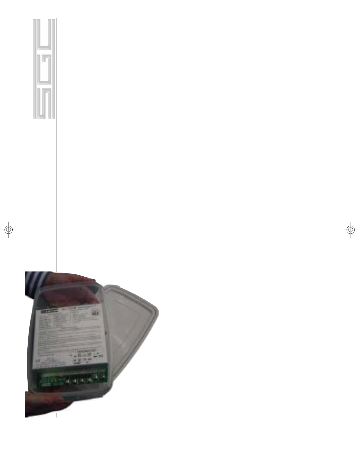
degradation of performance. To waterproof a SG-
239, place the unit in a sealable food con-
tainer, (1.7 liter - 7 cup standard size)
2.2 Desert and High Temperature
Installations
The Smartuner may be used in very hot cli-
mates on a continuous basis if some additional
protection from direct sunlight is provided and if
coupler is installed in a waterproof case. Tempera-
tures inside a vehicle may exceed 212°F (100°C). It is
desirable to keep the coupler in the shade if possible.
SG-239 Manual
page 6 Wednesday, October 17, 2001 08:31
Composite
Mailing: PO Box 3526, Bellevue, WA 98009
Shipping: 13737 SE 26th St., Bellevue, WA 98005
Toll-Free: 800-259-7331 • Phone 425-746-6310 • Fax: 425-746-6384
www.sgcworld.com • Email: sgc@sgcworld.com
7
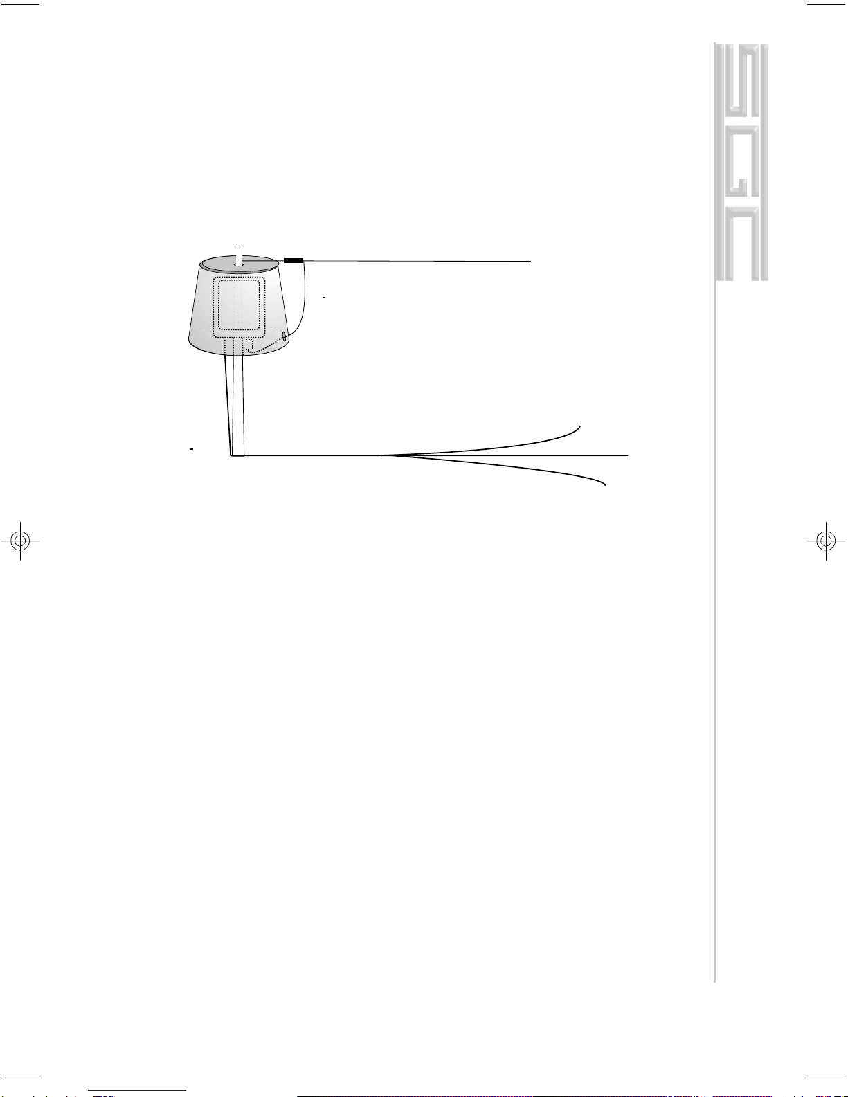
2.3 Direct Weather Protection Installations
To protect the unit from direct exposure to sunlight and to prevent
heavy build up of ice, we recommend installing the Smartuner first in
a waterproof case then placing the case under some kind of protective
housing. If you are mounting it on a tower in a hot or cold climate, a
plastic wastebasket (such as those made by Rubbermaid™) makes an
excellent weather cover and costs only a few dollars.
3.0 Coupler Configuration
Schematic Q30102900A, pg. 26, sheet 1 of 6, is the schematic dia-
gram of the two basic coupler networks L & PI. Note that the L net-
work as viewed from the generator, may be configured as either “C
in” or “C out,” whichever is required by the load. In either case, the
end of the network containing the shunt C element will be the higher
impedance end of the network.
3.1 Connections to SG-239
Drawing G30102900A, pg. 26, sheet 1 of 6 and pg. 30, sheet 5 of 6,
are the diagrams of the antenna coupler connections. RF input and
ground is applied respectively to terminals “RF in” and GND.” The
DC input is applied with the positive to the “12V” DC terminal and
“GND DC.” The “TND” terminal can be connected to transceiver or
SmartLock. This line cannot be connected to both units simultane-
ously. The Hold/Reset terminal is to be reconnected to the SmartLock
option if used.
Smartuner mounted inside a plastic waste
basket to protect it from extreme heat and
heavy icing. This type of enclosure is widely
available in all countries.
Long wire antenna
SG-239 Manual
page 7 Wednesday, October 17, 2001 08:31
Composite

Mailing: PO Box 3526, Bellevue, WA 98009
Shipping: 13737 SE 26th St., Bellevue, WA 98005
Toll-Free: 800-259-7331 • Phone 425-746-6310 • Fax: 425-746-6384
www.sgcworld.com • Email: sgc@sgcworld.com
8
© 2001 SGC, Inc.
3.2 Tuning Process
An array of detector devices in the SG-239 monitor the antenna sys-
tem impedance, reactance signal, and the VSWR load when RF
power is applied to the unit. The coupler also monitors forward
power, since the control computer requires an indication of both for-
ward and reflected power in order to allow tuning to proceed. The
computer uses the forward power detector as a check to ensure that
the measurements made are applied RF and are not spurious levels
from the data conversion system. The SG-239 will proceed to tune
only when enough forward power is present to confirm this check.
After RF is applied to the detector system, it then passes through the
coupler tuning array. The coupler tuning array consists of six capaci-
tors in shunt on the input arm of the network, seven inductors in the
series arm, and four more capacitors in shunt on the output arm, all
arranged in binary increments. Relays are provided in conjunction
with each lumped constant and allow removal or entry as desired. A
network having 64 values on input shunt C, 16 values of output
shunt C, and up to 128 values of series L is possible with the ma-
nipulation of these 17 relays.
3.3 Impedance Detector
RF transformers T1 and T3 drive the impedance bridge that is bal-
anced at 50 ohms. T3 samples the line current and thus D7 out-puts a
negative DC level proportional to line current. A tertiary winding on
transformer T1 provides a line voltage sample to D2 that provides a
positive voltage proportional to line voltage. R18 and R11 act as a
summing network for the current and voltage signals, with ratios
chosen, such that at 50 ohms, the summed signals result in a bal-
anced or zero voltage condition. If the line impedance goes to high,
the signal from the voltage sensor will be relatively higher than the
current sensor, which will result in a net positive output voltage from
the summing network. Similarly, a low line impedance will result in
more output from the current sensor, resulting in a net negative out-
put voltage from the summing network. The summing network out-
put is shifted to a 0 to 5v range, then fed to the processor's A to D
converter port, and used within the micro-controller.
SG-239 Manual
page 8 Wednesday, October 17, 2001 08:31
Composite

Mailing: PO Box 3526, Bellevue, WA 98009
Shipping: 13737 SE 26th St., Bellevue, WA 98005
Toll-Free: 800-259-7331 • Phone 425-746-6310 • Fax: 425-746-6384
www.sgcworld.com • Email: sgc@sgcworld.com
9
3.4 VSWR Detector
A directional coupler is made up of a current transformer T2 and a
voltage transformer T1, in conjunction with termination resistors R35,
R36 and R33, R34. The coupler is inserted in the 50-ohm transmis-
sion line between the input connector, ST2 RF - ST3 GND, and the
tuning network. The forward power is measured across termination
R33, R34 and reflected power is measured across termination R35,
R36. Diode D1 generates a positive DC voltage proportional to for-
ward power and D3 generates a positive DC voltage proportional to
reflected power. The forward DC output is fed to a voltage divider
consisting of R19 and R14. These voltages are input to the RF power
detector and to an A to D converter port of the processor. The re-
flected DC output passes through a voltage divider consisting of R29
and R16, and then it also goes to an A to D converter port of the proc-
essor.
3.5 Phase Detector
A phase detector is formed by T3, A1, and their associated compo-
nents. This detector indicates the state of any reactance associated
with the antenna coupler as noted from the generator. A line current
sample is compared in phase with a voltage sample in a double bal-
anced mixer. Output polarity varies negative or positive depending on
the reactance of the antenna. The output of the phase detector A1 is
shifted to a 0 to 5v range, then fed to the processor’s A to D converter
port and used within the micro controller.
3.6 Central Processing Unit (CPU)
A tune-up algorithm, which is contained in the memory of the micro-
processor, implements the antenna matching. It is designed around the
MC68HC711E9 CPU that features a versatile instruction set, RAM,
and EEPROM (memory which is saved after the coupler is turned
off). The antenna coupler relays are controlled by latches U6 and U7,
which receive serial data input directly from the CPU. During opera-
tion, data is transferred into the CPU from the A to D ports and Input
Capture port (measures RF frequency). Basically, the program moni-
tors the status of the input sensors and—starting from a preset condi-
tion—uses a built-in algorithm to achieve a tuned condition. When the
SG-239 Manual
page 9 Wednesday, October 17, 2001 08:31
Composite

Mailing: PO Box 3526, Bellevue, WA 98009
Shipping: 13737 SE 26th St., Bellevue, WA 98005
Toll-Free: 800-259-7331 • Phone 425-746-6310 • Fax: 425-746-6384
www.sgcworld.com • Email: sgc@sgcworld.com
10
© 2001 SGC, Inc.
tuning algorithm is complete, the CPU saves the settings in its
EEPROM, which is addressed by the applied RF frequency. This
non-volatile memory table is the basis of the exclusive learning fea-
ture of the SG-239. After it has stored and latched the network status,
the CPU waits for RF to cease transmitting and returns to the Stop
mode. When RF is re-transmitted, the first step in the tuning algo-
rithm is to measure the frequency of the signal passing through the
coupler. From the frequency data, the computer then searches its
EEPROM for previously stored data. If data is found, it is tested for
validity, and the required “end of tune” conditions will be sensed by
the RF sensors. Then the data will be latched in place, and the CPU
will again wait for RF to cease transmitting and turn to the Stop
mode. This process takes about 10 milliseconds, which is the same
length of time that is required to close the network relays.
3.7 Initialization
The microcomputer is usually in the Stop mode and requires an in-
terrupt signal (XIRQ) to start program implementation. The XIRQ is
obtained from the RF detector circuitry. This line, going low, will
wake the CPU from the Stop mode.
3.8 Jumper settings
The SG-239 may be bypassed for broad band (un-tuned antenna)
scanning listening in receive mode. All you need to do is press the
reset button of the SmartLock (if installed) or turn power to the cou-
pler off and on. When the coupler comes back on, the tuning ele-
ments remain out of the circuit until the Smartuner is activated by a
transmitted signal. If broad band operation is required during receive
for scan operation, jumper JP1 may be set to the Yes position. This
will drop the tuning elements out of the circuit on receive only.
Jumper JP1 is located adjacent to MCU (U5) along the edge of the
printed circuit board. Setting JP1 to the Yes position is recom-
mended if you are using a radio for split band communications, for
scanning selective calling protocols, or for Automatic Link Estab-
lishment (ALE). The default is: Tuning Out In Rcv: [NO].
Jumper JP3 bypasses the coupler's memories. This means that each
time the coupler is used on a different frequency, it will re-tune
SG-239 Manual
page 10 Wednesday, October 17, 2001 08:31
Composite
Mailing: PO Box 3526, Bellevue, WA 98009
Shipping: 13737 SE 26th St., Bellevue, WA 98005
Toll-Free: 800-259-7331 • Phone 425-746-6310 • Fax: 425-746-6384
www.sgcworld.com • Email: sgc@sgcworld.com
11
rather than use previously stored information. The default is: Tune
From Memory: [YES].
4.0 Tuning Process and Options
MicroTune™ Software
Copyright 1991-2001
The SG-239 MicroTune™ Software is unique software which allows
precise tuning of the digitally controlled π and L network to tune a
wide variety of antennas. The versatile MicroTune™ software offers
its user these special functions:
1. The coupler is activated whenever forward power is present.
2. In addition to sampling VSWR to determine if the coupler should
re-tune, frequency comparison is employed. This causes the coupler
to tune when ever the transmit frequency changes independent of the
VSWR reading.
3. Extensive tuning paths are used to test different antenna situations.
The initial tuning of a new frequency (or switched antenna) may re-
quire up to two seconds. Any further tuning is accomplished in a mat-
ter of milliseconds if jumper JP3 (Tune From Memory) is in its de-
fault position.
4. Facilities and algorithms are used which enable accurate tuning at
the low end of the frequency band—even on shorter antennas than
previously possible.
5. The BITE (Built-In-Test-Equipment) Indicator Tune LED includes
a safety feature that alerts the operator to a mismatched condition,
with blinking indicators, when proper tuning conditions have not been
met. In this situation, the software will “time out” within 20 seconds
unless a new frequency is sensed, which will cause an immediate time
out, and the coupler will attempt to match the new frequency. The mi-
croprocessor of the coupler “wakes up” every time the coupler has
forward power. However, re-tuning takes place only if the frequency
has changed or the VSWR exceeds 2:1.
4.1 Program Description
When DC power is applied, the computer initializes the processor reg-
isters in accordance with the hardware. All tuning elements are then
SG-239 Manual
page 11 Wednesday, October 17, 2001 08:31
Composite

Mailing: PO Box 3526, Bellevue, WA 98009
Shipping: 13737 SE 26th St., Bellevue, WA 98005
Toll-Free: 800-259-7331 • Phone 425-746-6310 • Fax: 425-746-6384
www.sgcworld.com • Email: sgc@sgcworld.com
12
© 2001 SGC, Inc.
removed and the 'tune' indicators are turned off. At this time the
computer reverts to a "sleep" mode awaiting RF power or pushbut-
tons S2-S8 in Manual Mode.
4.1.1 Auto Mode
Detecting forward power. Once forward power is detected and the
optional SmartLock is switched to Normal, the current coupler set-
tings are sent to the relays. Next, the VSWR is checked and the fre-
quency measured. If the VSWR is greater than 2:1 or a difference in
frequency is detected, the program branches to the re-tune program.
If it is determined that the VSWR is less than 2:1 and the frequency
has not changed, the computer returns to the Stop mode. Re-tuning.
Once it is determined that re-tuning is necessary, a test is made to see
if JP3 is set to tune from memory. If the result is re-tuning from
memory, settings are recalled from the EEPROM based on the fre-
quency measured. The recalled data is then tested for validity. If the
data proves invalid, it is bypassed and re-tuning is performed. If the
data recalled proves valid, the data is sent to the relays and the
VSWR is checked. If the VSWR is less than 2:1, the program
branches to the “OK Tuned” section of the program. If the VSWR is
found to be greater than 2:1, the program branches to the “re-tune”
program.
Selecting tuning path. Several tests are made to determine which tun-
ing algorithm or path should be used to tune the coupler. These tests
are based on frequency, antenna input impedance, antenna phase,
and VSWR. Numerous subroutines are executed repeatedly, depend-
ing on the status of the criteria mentioned above, in order to achieve
proper tuning.
Signaling “no-tune.” Should the initial primary tuning sequence
prove unsuccessful, secondary algorithms are attempted until all pos-
sible routines have been exhausted. If, after the secondary attempts,
the coupler still cannot achieve a proper VSWR, the program
branches to a “no-tune” program. Here, the LED's and remote tune
indicator will blink on and off for about 15 seconds to tell the user a
proper VSWR could not be found. After the indicators stop blinking,
SG-239 Manual
page 12 Wednesday, October 17, 2001 08:31
Composite

Mailing: PO Box 3526, Bellevue, WA 98009
Shipping: 13737 SE 26th St., Bellevue, WA 98005
Toll-Free: 800-259-7331 • Phone 425-746-6310 • Fax: 425-746-6384
www.sgcworld.com • Email: sgc@sgcworld.com
13
the program waits for forward power to cease (if it has not ceased al-
ready) and returns to stop mode. At this point the user should try sev-
eral other frequencies. If the “no-tune” condition persists, check the
installation of the antenna, coupler, radio, and ground system for pos-
sible problems.
Signaling “OK tune.” If the coupler achieves a good VSWR during
the tuning sequence, the program branches to the “OK Tune” section
of the code. Here, the tune indicators are engaged. A test is then made
to check if JP3 is set to tune from memory. If so, the frequency is
measured and the tuning elements used are saved in memory coupled
with a verification code. Once saved, a test is made on JP1 to check if
the duplex mode has been selected. If so, the transmit tuning elements
remain in circuit until the receive mode is verified. At this time, all
tuning elements are removed. The frequency is then saved for future
comparison and the CPU reverts back to the STOP mode.
4.1.2 Manual Mode
Manual Mode allows user to adjust and save settings with or without
RF power applied. See section 6 for details on use in manual mode.
4.2 Tuning Paths
As mentioned previously, various tests are executed to determine the
most logical tuning sequence to be performed. Dependent on the test
results, additional tests and appropriate sub-routines are executed
throughout the tuning process. Following are examples of the activity
that occurs when the coupler must be matched to a frequency that re-
quires a slightly longer or shorter antenna:
4.2.1 Antenna Too Short
Once coupler has verified RF power, tuning sequence proceeds as fol-
lows:
1. Series inductance is added until the phase is deemed as being in-
ductive. At this point it is normal for the input impedance to be low.
2. Input capacitance is added until the antenna is no longer inductive.
3. The program will continue to increment the series inductance
in .125 µH steps—each time normalizing the input impedance with
SG-239 Manual
page 13 Wednesday, October 17, 2001 08:31
Composite

Mailing: PO Box 3526, Bellevue, WA 98009
Shipping: 13737 SE 26th St., Bellevue, WA 98005
Toll-Free: 800-259-7331 • Phone 425-746-6310 • Fax: 425-746-6384
www.sgcworld.com • Email: sgc@sgcworld.com
14
© 2001 SGC, Inc.
input capacitance until a low VSWR is measured of less than 2:1.
This process will continue until the VSWR has climbed back to
higher than 2:1 or the impedance has become high.
4. The settings that gave the lowest VSWR have been kept in mem-
ory and are now recalled to verify it is a low VSWR
5. At this point the tune indicators are engaged. The current relay
data is saved if JP3 is set to tune from memory; if JP1 is set to tune
elements out during receive position, the program waits until forward
power is no longer present, then removes all tuning elements. The
frequency is saved for future frequency comparison, and the com-
puter reverts to Stop mode.
4.2.2 Antenna Too Long
Once the coupler has verified RF power, the tuning sequence pro-
ceeds
as follows:
1. Output capacitance is added until the phase switches to capacitive.
2. At this point, series inductance is added until the antenna is no
longer capacitive.
3. Fine tuning is performed by trying a small amount of input capaci-
tance (this may or may not be required).
4. At this point, the program executes the same as step 5 (antenna too
short).
The preceding gives a simplified program flow on only two possible
antenna conditions. Much more complex tuning is normally the case.
Further detailed description, however, is beyond the scope of this
manual.
4.2.3 JP1—Tuning Elements Out During Receive
(Factory Default Setting: No)
YES - In this position the software will retain data required in trans-
mit to match the coupler while removing all tuning elements when
no forward power is detected.
NO - In this position the coupler will retain the required tuning data
and will change nothing whether in receive or transmit. If typical
operation is out of band duplex, Yes would be most likely to give
better performance. If in band operation is typical and duplex or sim-
SG-239 Manual
page 14 Wednesday, October 17, 2001 08:31
Composite

Mailing: PO Box 3526, Bellevue, WA 98009
Shipping: 13737 SE 26th St., Bellevue, WA 98005
Toll-Free: 800-259-7331 • Phone 425-746-6310 • Fax: 425-746-6384
www.sgcworld.com • Email: sgc@sgcworld.com
15
plex is the predominant mode of operation, then No is usually the bet-
ter choice.
4.2.4 JP3—Tune From Memory
(Factory Default Setting: Yes)
YES - In this position the coupler will recall data previously saved
and try this data before attempting to re-tune. If the data is valid and
the VSWR is less than 2:1 the tune is completed. In this position the
coupler will save any new data in its memory for any frequency. A
new frequency must first be learned, while in this mode, before it can
be recalled.
NO - In this position, the coupler will not use previously saved tuning
data. Each time a different frequency is selected, the coupler will pro-
ceed through a complete tuning sequence. Clearly, the advantage of
Yes is speed. The coupler will seem to be matched instantly when in
this position, if the frequency being used has previously been saved in
EEPROM. Disadvantages include a difference in frequency too small
for the computer to detect. This would result in recall of valid data
that may not necessarily present the best match. We suggest starting
with JP3 in the Yes position. If operation is as expected, don't change
it.
5.0 B.I.T.E.* Status LED Descriptions
*Built In Test Equipment
TND
This LED will light when the tuner has found an acceptable match. It
will remain lit until conditions have changed which will cause the
tuner to find a different match. (i.e. A new transmit frequency has
been detected, or tuner has been reset.)
L'Z'
This LED shows the status of the antenna impedance. When lit, the
impedance is 50 ohms or less. When off, the impedance is greater
than 50 ohms.
SG-239 Manual
page 15 Wednesday, October 17, 2001 08:31
Composite

Mailing: PO Box 3526, Bellevue, WA 98009
Shipping: 13737 SE 26th St., Bellevue, WA 98005
Toll-Free: 800-259-7331 • Phone 425-746-6310 • Fax: 425-746-6384
www.sgcworld.com • Email: sgc@sgcworld.com
16
© 2001 SGC, Inc.
2:1
This LED will light when the VSWR is greater than 2:1. It will ex-
tinguish when VSWR is less than 2:1.
PHZ
This LED indicates the status of the antenna reactance. When lit, re-
actance is inductive. When off, reactance is capacitive.
FWD
This LED indicates the presence or lack of RF power from the radio.
When transmitting, the LED will light to indicate RF is being de-
tected. In receive, the LED should be extinguished.
OTHER
All LEDs will blink on and off at a rate of 2Hz to indicate the tuner
was not able to find a valid match.
Note that these status LEDs are usually used to aid a technician in
diagnosing the status of the antenna system and should not be
thought of as laboratory instruments.
As the Smartuner tunes, the BITE status will be continually updated
from the CPU.
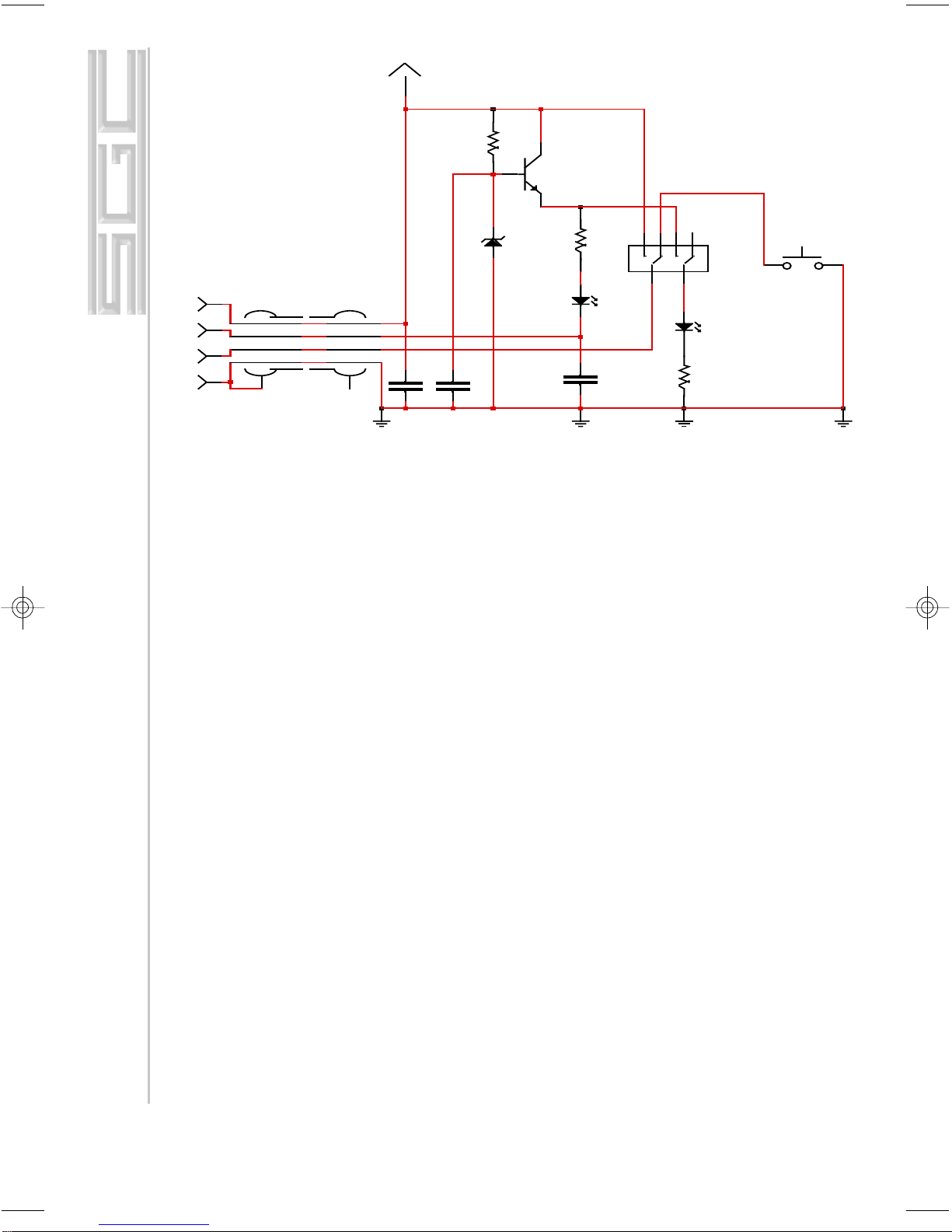
6.0 Optional SmartLock
The SmartLock allows the operator to have additional control over
the SG-239. It is not required for normal operation of the coupler.
One can be purchased by SGC or made per the description of the
schematic in paragraph 5.2. The SmartLock provides two basic func-
tions:
1. To lock the coupler in the last tune mode regardless of any
changes made by the operator on the transceiver or external changes
that may have occurred on the antenna. It is a very convenient func-
tion especially for instable antennas (such as whip antennas on a car
in motion) or instable situations due to a system installation or con-
figuration. However, using it in this mode may be hazardous as the
SG-239 Manual
page 16 Wednesday, October 17, 2001 08:31
Composite

Mailing: PO Box 3526, Bellevue, WA 98009
Shipping: 13737 SE 26th St., Bellevue, WA 98005
Toll-Free: 800-259-7331 • Phone 425-746-6310 • Fax: 425-746-6384
www.sgcworld.com • Email: sgc@sgcworld.com
17
operator may change frequency and the coupler will not tune. It may
eventually burn coils and/or relays.
2. Reset function is convenient to force a reset in situations where a
coupler will not retune. For example, the last tune achieved on 14.100
with VSWR 1:1.7, the coupler is instructed not to retune until it
reaches 1:2.0 - If the coupler is reset and therefore will retune at your
next transmission it may tune to 1:1.1 or much better before the last
read of 1:1.7 - reset can also be used to listen to other frequencies out
of band of your last setting in a broad band mode, and therefore in-
creasing your incoming receive level by several “S” units. Reset is
also accomplished by turning power off and on again.
6.1 Tune, Tune Lock/Reset
Tuned (green LED)
Turns on when the coupler has successfully tuned.
Normal/Tune Lock
Toggle switch which allows user to prevent coupler re-tuning by
switching to the Tune Lock position. When in the Tune Lock position,
the red LED blinks to notify the user that the coupler is locked on the
current setting.
Reset
Pushing the red reset button allows the coupler to be reset, if the tog-
gle switch is in the normal position. This is preferred over turning the
input power off and on.
6.2 SmartLock Notes
The Tune Lock function is in most cases unneeded. Inadvertent retun-
ing is a rare occurrence. Retuning may occur when the environment or
antenna system has changed. In this case, retuning is within normal
operation of the coupler.
SG-239 Manual
page 17 Wednesday, October 17, 2001 08:31
Composite
Mailing: PO Box 3526, Bellevue, WA 98009
Shipping: 13737 SE 26th St., Bellevue, WA 98005
Toll-Free: 800-259-7331 • Phone 425-746-6310 • Fax: 425-746-6384
www.sgcworld.com • Email: sgc@sgcworld.com
18
© 2001 SGC, Inc.
7.0 SG-239 Enhanced Features
1. Clear (Erase) all 170 memory bins
A. Set Auto-Manual slide switch position to AUTO.
B. Remove DC power from SG-239
C. Depress both ‘Cin Up’, (S3) and ‘Cout Dn’, (S8). Keep
both depressed for next step (Step D).
D. Apply DC power to SG-239. In less than one second, all
status LED’s will start to flash on and off.
E. Once LED’s start flashing, memory will have been
erased and S3 and S8 can be released.
End of procedure
2. Clear single unit memory bin
A. Set auto-manual slide switch position to auto.
B. Transmit on frequency to recall desired memory bin.
C. Switch the transceiver to receive mode.
D. Set auto-manual slide switch position to manual.
E. Momentarily depress ‘SAV’, (S2).
F. Return auto-manual slide switch position to auto.
G. Momentarily depress ‘SAV’ (S2). Current memory bin
has been erased.
SW2
PUSH Button
DS2
Red LED
R2
330
+13.6VSW
DS1
Gr een LED
R1
150 SW1
DPDT
CA1
C1
0.1µF
C2
0.1µF
R3
330
D1
1N757
C3
0.1µF
Q1
2N2222
3 4
52
61
TUNED FROM COUPLER NORMAL
RESET
GROUND
+13.6 VSW
Red
Gr een
Black
Whit e
RED
GREEN
WHITE
BLACK
NO TUNE /
RESET FROM COUPLER
SG-239 Manual
page 18 Wednesday, October 17, 2001 08:31
Composite

Mailing: PO Box 3526, Bellevue, WA 98009
Shipping: 13737 SE 26th St., Bellevue, WA 98005
Toll-Free: 800-259-7331 • Phone 425-746-6310 • Fax: 425-746-6384
www.sgcworld.com • Email: sgc@sgcworld.com
19
End of procedure
3. Manual tuning in transmit
A. Set auto-manual slide switch position to manual.
B. Engage transmitter. Not more than 10-15 watts is recom-
mended to avoid accidental RF burn.
C. Use S3 thru S8 to tune the SG-239. Each time a switch is
depressed, the status LED’s are updated.
D. You may save the settings for this frequency by momen-
tarily depressing ‘SAV’, (S2) while transmitting.
End of procedure
4. Manual tuning in receive - “Silent Tuning”
A. Set auto-manual slide switch position to manual.
B. Engage receiver.
C. Use S3 thru S8 to adjust for best receive signal. Note:
Status LED’s are not updated in receive.
D. See appropriate procedures for saving and recalling re-
ceive only memories (below in paragraphs 5 & 6).
End of procedure
5. Saving a receive only setting into memory
A. Set auto-manual slide switch position to manual
B. Momentarily depress ‘SAV’, (S2) the current RX memory
channel will be displayed with the status LED’s. (Far left
LED is channel 1). If no LED is lit, current channel is zero.
C. Select desired channel with S3 (Chan Up) and S8 (Chan
Dn). Current channel selected is updated as switches are de-
pressed.
D. Momentarily depress ‘SAV’ (S2) and current settings will
be saved to displayed RX memory bin. Note: Saving to chan-
nel zero aborts save.
End of procedure
6. Recall receive only channel from memory
A. Set auto-manual slide switch position to auto.
B. Momentarily depress ‘SAV’, (S2) the current RX memory
channel will be displayed with the status LED’s. (Far left
LED is channel 1). If no LED is lit, current channel is zero.
(recall channel zero aborts recall)
C. Select desired channel with S3 (Chan Up) and S8 (Chan
Dn). Current channel selected is updated as switches are de-
SG-239 Manual
page 19 Wednesday, October 17, 2001 08:31
Composite

Mailing: PO Box 3526, Bellevue, WA 98009
Shipping: 13737 SE 26th St., Bellevue, WA 98005
Toll-Free: 800-259-7331 • Phone 425-746-6310 • Fax: 425-746-6384
www.sgcworld.com • Email: sgc@sgcworld.com
20
© 2001 SGC, Inc.
pressed.
D. Momentarily depress ‘SAV’ (S2) and saved settings will
be recalled from displayed RX memory bin.
End of procedure
Additional Notes:
Note 1: Saving and recalling receive only memories
The two procedures are basically the same with the ex-
ception of the auto-manual slide switch.
SET TO MANUAL SAVE
SET TO AUTO RECALL
Note 2: Fine tuning a transmit frequency
Auto tune the frequency as normal.
Switch auto-manual to manual
Fine tune settings with S3-S8
While transmitting, depress ‘SAV’ (S2) to update trans-
mit memory bin.
8.0 Do-It-Yourself Light-Bulb Dummy Load
Any time that a transmitter is used, it must be outputting into a load.
A load is anything that the output power can be pumped into. If the
transmitter is operated without any sort of load connected, the final
amplifier stage could become severely damaged. The problem is that
you should never test a transmitter on the air for the first time, if you
are unsure about how to operate it, and if you are unsure whether it is
working properly. You could create harmful interference to other
stations.
To test transmitters without actually operating into an antenna,
dummy loads were created. A dummy load is a load that will dissi-
pate the energy from the transmitter instead of emanating it into the
ionosphere. Nearly all commercial dummy loads are large oil-filled
cans. These dummy loads change the transmitted energy into heat,
which is absorbed by the oil. Because different transmitters output
different amounts of power, different sizes of dummy loads must be
used. Dummy loads for typical amateur powers (<500 watts) are
relatively inexpensive and are readily available.
SG-239 Manual
page 20 Wednesday, October 17, 2001 08:31
Composite
Table of contents
Other SGC Tuner manuals


