manuals.online logo
Brands
  1. Home
  2. •
  3. Brands
  4. •
  5. Sharon Piping & Eqpt
  6. •
  7. Control Unit
  8. •
  9. Sharon Piping & Eqpt Sharpe Valves 53034 Manual

Sharon Piping & Eqpt Sharpe Valves 53034 Manual

3
-
PIECE FULL PORT BALL VALVE
–
MODELS 53034 & 53036
INSTALLATION, OPERATION, AND MAINTENANCE INSTRUCTIONS
IM
-
53
-
1 (6/04)
INSTALLATION:
These valves may be installed in the pipeline in
any orientation or position, using good piping
practice. For threaded end valves, use a
suitable joint compound or TFE tape on pipe
threads for ease of fit-up.
Welding End Valves:
Socket weld and butt weld end valves must be
partially disassembled to prevent heat damage
during welding of the soft plastic seats andseals
in the valve. Prior to disassembly, the valve
may be temproarily fitted in line, and the ends
tack-welded to the piping for alignment
purposes.
With the valve in the open position, remove the
body hex nuts and lockwashers, and the body
hex bolts. Carefully lift out the center section,
making sure that the seats and body seals are
held in position. Place the center section in a
clean area where it will not be damaged, and
complete the welding of the end caps to the
piping.
When the welds are cool to the touch, reinstall
the center section of the valve between the body
end caps. Take care that the seats and seals
are in place, and have not been damaged. Re-
install the body bolting, and tighten following the
“Assembly” instructions on the following page.
OPERATION:
These are quarter-turn (90° rotation) ball valves,
and are normall fitted with a latching lever
handle for manual operation. The handles also
contain travel stop tabs at the open and closed
positions. To open the valve, lift the latch/lock
slider up, and turn the handle clockwise. To
close the valve, lift the latch/lock and turn the
handle counterclockwise.
For valves fitted with power actuators, operating
instructions are contained in the manuals
supplied with the actuator and accessories.
MAINTENANCE:
----WARNING----
Do not attempt to perform
maintenance on valves in
pressurized lines.
Stem Seal Adjustment:
If leakage is evident from the stempackingarea,
tighten the packing gland (below the handle) 1/8
turn. If the leakage persists, repeat tightening.
If leakage cannot be corrected by tightening the
gland, replacement of the stem seals will be
necessary.
Seal Replacement:
Turn valve to the open position and remove
handle nut, lockwasher, and handle. Loosen
and remove packing gland from valve body.
Loosen and remove body bolts, and remove
body center section assembly, placing it on a
suitable work surface. Remove seats and body
seals.
Using the handle if necessary, turn ball to the
closed position, and remove ball from body with
a rolling motion away from the stem. Handle
ball with care to avoid damaging the surface.
Push downwards on the top of the stem to slide
it through the stem seals, and remove stem from
inside body bore. Remove thrust washer from
stem, or from body bore if retained in body.
Remove stem seals using a packing hook or
sharp object.
Sharpe recommends that all soft parts, including
seats be replaced with new parts, which can be
ordered in kit form.
REASSEMBLY:
Make sure all valve components are clean and
undamaged before assembly.
Install thrust washer on stem, and slide down to
shoulder. Insert stem into body and upwards
through the stem bore until the shoulder is
seated in the bore.
Slide stem seal over stem top, and into stem
bore in body. Take care not to damage seal on
stem threads. Install packing gland, and tighten
finger tight.
Place stem in the “closed” position, and install
the ball carefully by rolling the stem tang into the
ball slot.
Install seats in the body at both ends, making
sure the concave face fits against the ball, and
press the body seals into the grooves in the
body faces.
Turn ball to the “open” position, and replace
between the end caps in line. Slide body hex
bolts through end caps and body guide holes,
and secure with lockwashers and hex nuts.
Tighten snugly.
Tighten packing gland to the torque value givn in
the table below, and replace the handle,
lockwasher, and handle nut.
Tighten the body bolting to the torque values
given in the table below, using a cross or star
pattern to tighten evenly.
Table 1 –Assembly Torques
Valve Size Gland
Torque
(in-lb)
Body Bolt
Torque (in-
lb)
¼” – 3/8” 35 50
½” 35 110
¾” – 1” 80 115
1-1/4” –
1-1/2” 115 120
2” 115 125
2-1/2” 250 350
3” – 4” 350 460
1260 Garnet Drive, Northlake, Illinois 60164-1028 Phone (630) 883-8020 Fax:(630) 833-2661 www.sharpevalves.com

This manual suits for next models

1

Popular Control Unit manuals by other brands

Libelium Waspmote LoRaWAN Networking guide

Libelium

Libelium Waspmote LoRaWAN Networking guide

Lutron Electronics QS Timeclock Installation and operation guide

Lutron Electronics

Lutron Electronics QS Timeclock Installation and operation guide

Broan VAUTOW Installation and user guide

Broan

Broan VAUTOW Installation and user guide

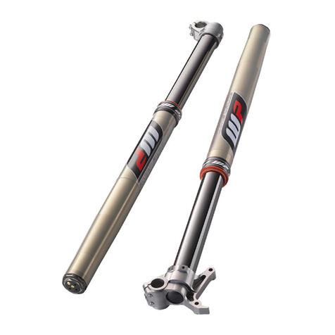
WP MXMA 4800 Workshop manual

WP

WP MXMA 4800 Workshop manual

Meec tools 080-208 Operating instructions in original

Meec tools

Meec tools 080-208 Operating instructions in original

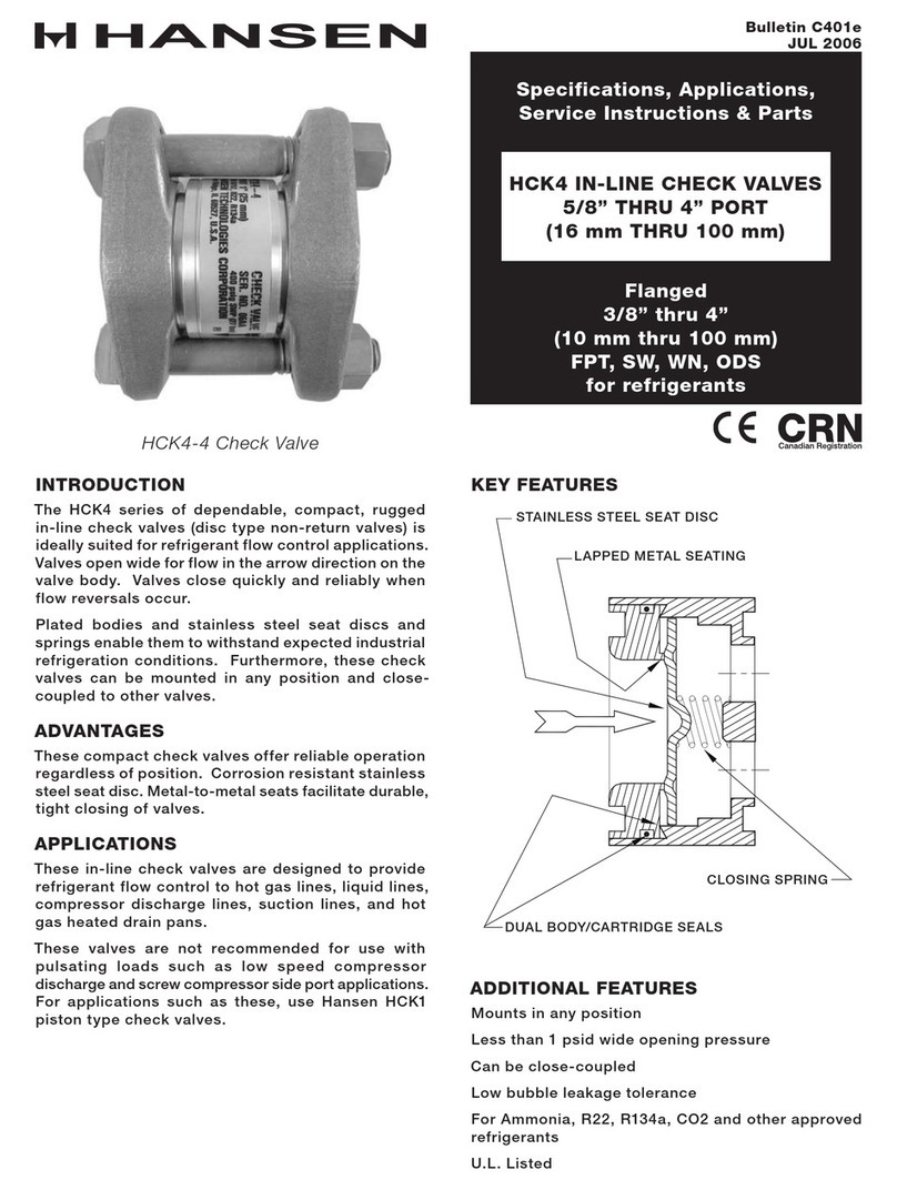
Hansen HCK4-2 Specifications, Applications, Service Instructions & Parts

Hansen

Hansen HCK4-2 Specifications, Applications, Service Instructions & Parts

LEGRAND 0 676 94 quick start guide

LEGRAND

LEGRAND 0 676 94 quick start guide

Eaton PKE-SWD-32 Instruction leaflet

Eaton

Eaton PKE-SWD-32 Instruction leaflet

Emerson HF Instruction

Emerson

Emerson HF Instruction

Siemens SITRANS PCS 7 Function manual

Siemens

Siemens SITRANS PCS 7 Function manual

AVG Automation EZTouch I/O Flex Series manual

AVG Automation

AVG Automation EZTouch I/O Flex Series manual

Eaton COOPER POWER SERIES Installation and operation instructions

Eaton

Eaton COOPER POWER SERIES Installation and operation instructions

Advanced Energy Thyro-Power Manager operating instructions

Advanced Energy

Advanced Energy Thyro-Power Manager operating instructions

OMC VD10 Series Installation, operation and maintenance manual

OMC

OMC VD10 Series Installation, operation and maintenance manual

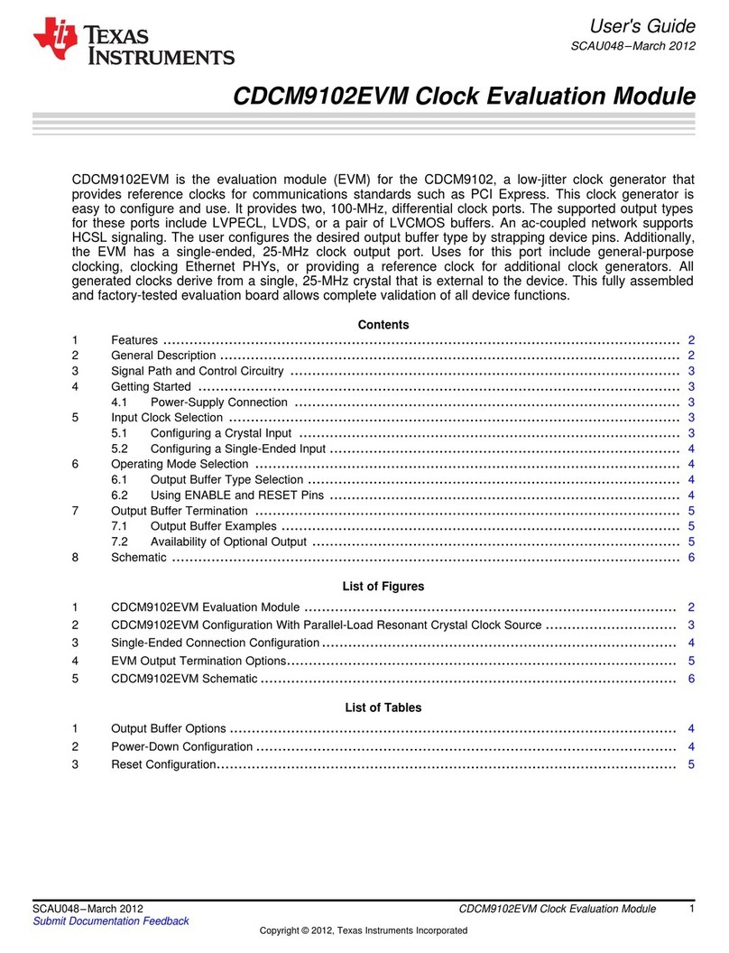
Texas Instruments CDCM9102EVM user guide

Texas Instruments

Texas Instruments CDCM9102EVM user guide

Worcester Comfort+ II RF Installation and operating instructions

Worcester

Worcester Comfort+ II RF Installation and operating instructions

Automationdirect.com GSDA-CM-8 user manual

Automationdirect.com

Automationdirect.com GSDA-CM-8 user manual

Texas Instruments DRV10964 user guide

Texas Instruments

Texas Instruments DRV10964 user guide

manuals.online logo
manuals.online logoBrands
  • About & Mission
  • Contact us
  • Privacy Policy
  • Terms and Conditions

Copyright 2025 Manuals.Online. All Rights Reserved.