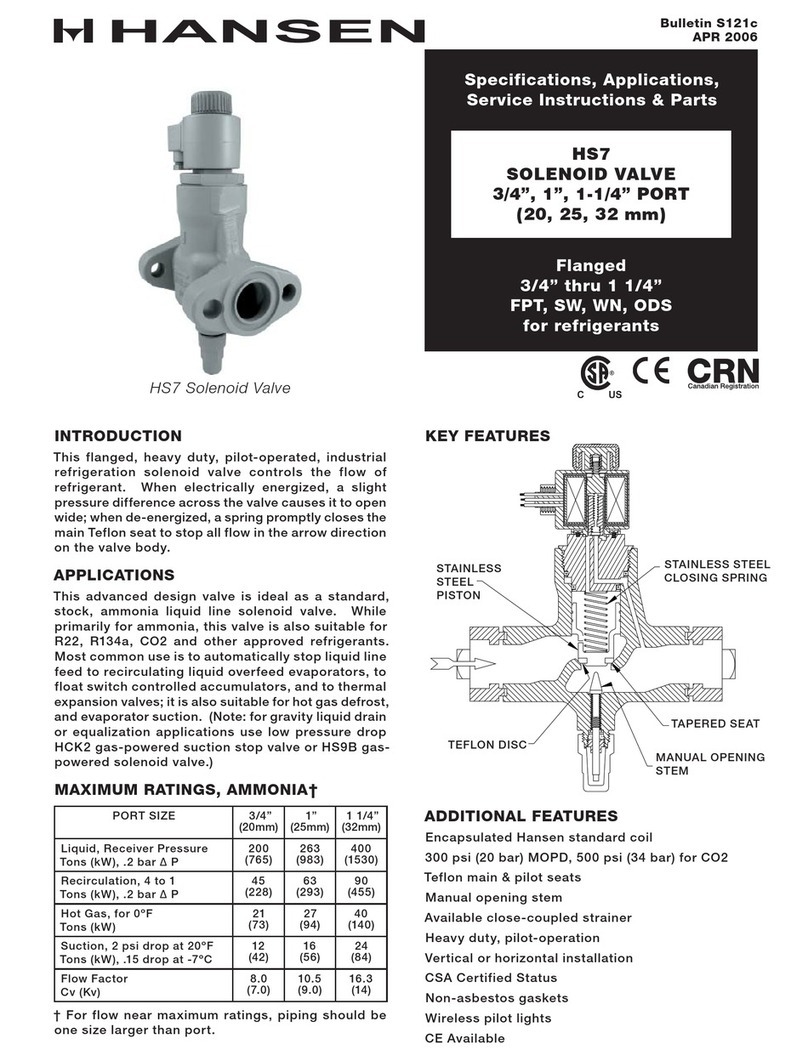
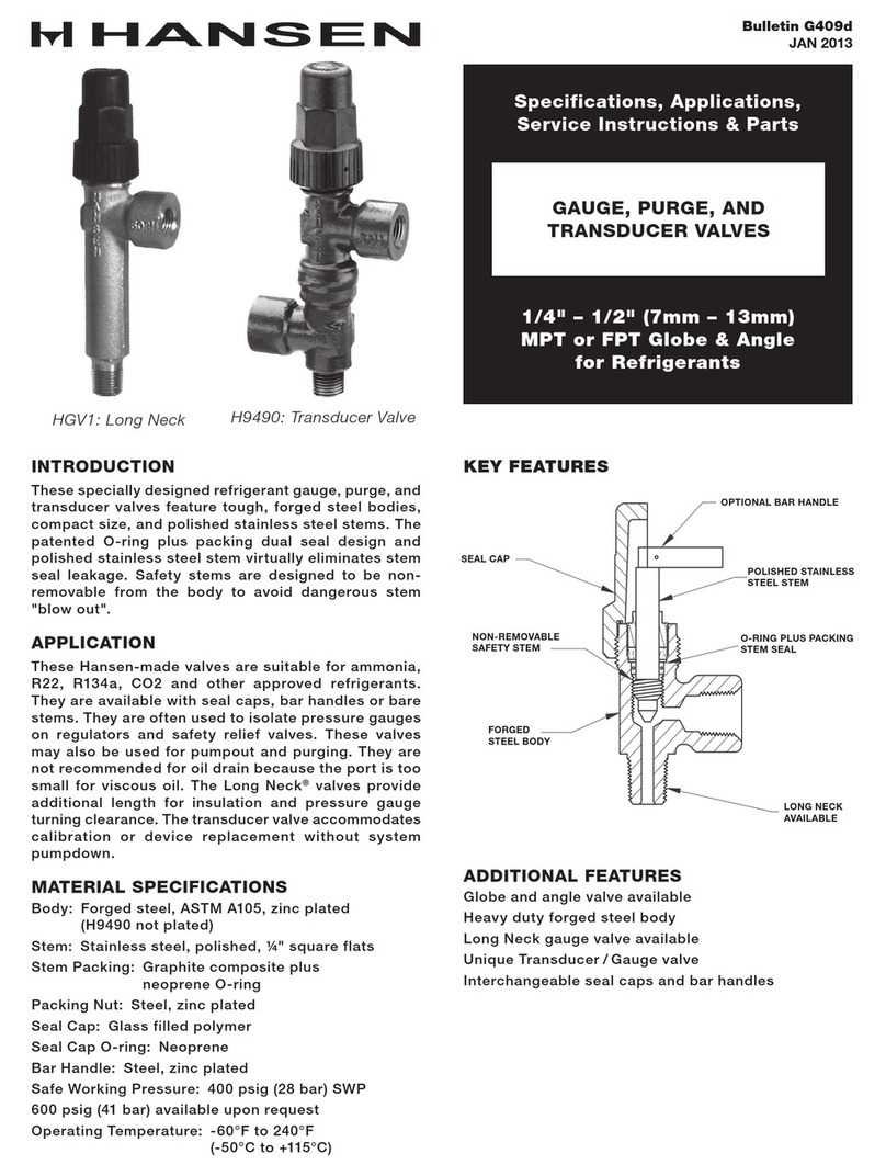
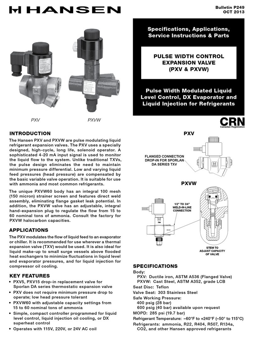
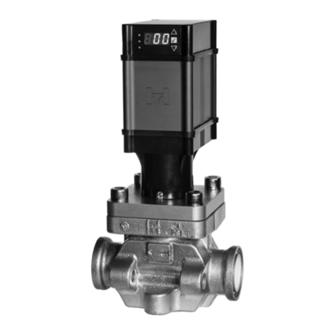
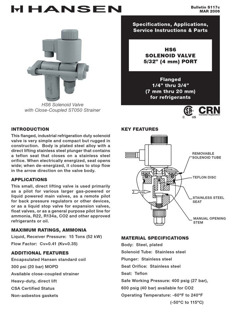
Hansen HCK4-2 Operating instructions

Specifications, Applications,
Service Instructions & Parts
HCK4 IN-LINE CHECK VALVES
5/8” THRU 4” PORT
(16 mm THRU 100 mm)
Bulletin C401e
JUL 2006
Flanged
3/8” thru 4”
(10 mm thru 100 mm)
FPT, SW, WN, ODS
for refrigerants
HCK4-4 Check Valve
INTRODUCTION
The HCK4 series of dependable, compact, rugged
in-line check valves (disc type non-return valves) is
ideally suited for refrigerant flow control applications.
Valves open wide for flow in the arrow direction on the
valve body. Valves close quickly and reliably when
flow reversals occur.
Plated bodies and stainless steel seat discs and
springs enable them to withstand expected industrial
refrigeration conditions. Furthermore, these check
valves can be mounted in any position and close-
coupled to other valves.
ADVANTAGES
These compact check valves offer reliable operation
regardless of position. Corrosion resistant stainless
steel seat disc. Metal-to-metal seats facilitate durable,
tight closing of valves.
APPLICATIONS
These in-line check valves are designed to provide
refrigerant flow control to hot gas lines, liquid lines,
compressor discharge lines, suction lines, and hot
gas heated drain pans.
These valves are not recommended for use with
pulsating loads such as low speed compressor
discharge and screw compressor side port applications.
For applications such as these, use Hansen HCK1
piston type check valves.
KEY FEATURES
ADDITIONAL FEATURES
Mounts in any position
Less than 1 psid wide opening pressure
Can be close-coupled
Low bubble leakage tolerance
For Ammonia, R22, R134a, CO2 and other approved
refrigerants
U.L. Listed
STAINLESS STEEL SEAT DISC
LAPPED METAL SEATING
CLOSING SPRING
DUAL BODY/CARTRIDGE SEALS

2
C401e
JUL 2006
MATERIAL SPECIFICATIONS
Body:
5/8” thru 1¼”: Steel, ASTM A108, zinc chromate
plated
1½” thru 4”: Ductile iron, ASTM A536, zinc chromate
plated
Seat Disc: Stainless steel
Seat Cartridge:
5/8” thru 1¼”: Stainless steel, ASTM A582
1½” thru 4”: Steel, ASTM A108, zinc chromate
plated
Spring: Stainless steel
Safe Working Pressure: 400 psig (27 bar), 600 psig
(40 bar) for CO2
Operating Temperature: -60ºF to 240ºF (-50ºC to
115°C)
INSTALLATION
Valve may be located in any position. Arrow on valve
body should match direction of flow. Secure valve
with gaskets between flanges and tighten bolts evenly.
Do not use this valve or any component to align pipes
or tighten gap between flanges.
Do not install on inlet side of solenoid valves or control
valves with electric shut-off or shut-off valves unless
a relief valve is used from therein between piping. Do
not install on inlet side of outlet pressure regulators
where liquid may become trapped. Instead, check
valves should be located on outlet side of these valves.
Check valves can be close-coupled to other matching
solenoid valves, pressure regulators, or strainers by
using a Male Adapter Ring and longer bolts supplied
when so specified on order. For proper flange gasket
sealing, care must be taken when threading or welding
to assure flanges are parallel to each other and
perpendicular to pipe. Also, gaskets should be lightly
oiled and all bolts must be tightened evenly.
INSTALLATION DIMENSIONS
B
A
E
C
F
G
H
G
HDK
J
INSTALLATION DIMENSIONS
DIMENSION
LETTE R
HCK4 -2
5/8” PORT
HCK4 -3
3/4” PORT
HCK4 -4
1” P ORT
HCK4 -5
1-1/4” PORT
HCK4 -7
1-1/2” PORT
HCK4 -8
2” P ORT
HCK4 -9
2-1/2” PORT
HCK4 -0
3” PORT
HCK4 -1
4” PORT
A2.50”
(64mm)
3.25”
(83mm)
3.25”
(83mm)
3.25”
(83mm)
5.06”
(129mm)
6.06”
(154mm)
6.06”
(154mm)
6.06”
(154mm)
6.39”
(162mm)
B3.19”
(81mm)
4.50”
(114mm)
4.50”
(114mm)
4.50”
(114mm)
4.56”
(116mm)
4.56”
(116mm)
6.00”
(152mm)
6.00”
(152mm)
7.13”
(181mm)
C3.50”
(89mm)
4.50”
(114mm)
4.50”
(114mm)
4.50”
(114mm)
6.38”
(162mm)
6.38”
(162mm)
7.50”
(191mm)
7.50”
(191mm)
8.00”
(203mm)
D0.38”
(10mm)
0.50”
(13mm)
0.50”
(13mm)
0.50”
(13mm)
0.75”
(19mm)
0.75”
(19mm)
1.00”
(25mm)
1.00”
(25mm)
1.00”
(25mm)
E=
1.03”
(26mm)
1.22”
(31mm)
1.22”
(31mm)
1.22”
(31mm)
2.56”
(65mm)
2.56”
(65mm)
2.92”
(74mm)
2.92”
(74mm)
3.50”
(89mm)
F1.50”
(38mm)
2.37”
(60mm)
2.37”
(60mm)
2.37”
(60mm)
3.62”
(92mm)
3.62”
(92mm)
4.84”
(123mm)
4.84”
(123mm)
6.06”
(154mm)
G1.56”
(20mm)
2.50”
(64mm)
2.50”
(64mm)
2.50”
(64mm)
4.56”
(116mm)
4.56”
(116mm)
6.00”
(152mm)
6.00”
(152mm)
7.13”
(181mm)
H2.19”
(56mm)
3.12”
(79mm)
3.12”
(79mm)
3.12”
(79mm)
3.06”
(78mm)
3.06”
(78mm)
4.00”
(102mm)
4.12”
(105mm)
5.00”
(127mm)
J3.26”
(83mm)
4.00”
(102mm)
4.00”
(102mm)
4.00”
(102mm)
6.06”
(154mm)
6.06”
(154mm)
7.06”
(179mm)
7.06”
(179mm)
9.89”
(251mm)
K0.33”
(8mm)
0.49”
(12mm)
0.59”
(15mm)
0.62”
(16mm)
0.71”
(18mm)
0.87”
(22mm)
0.96”
(24mm)
1.08”
(27mm)
1.40”
(36mm)
Valve Cv
(Kv) 5.8 (5) 8.2 (7) 11.7 (10) 14.0 (12) 39 (33) 50 (43) 74 (63) 93 (80) 210 (180)
Pipe Size 1/2”, 3/4” 3/4” 1” 1-1/4” 1-1/2” 2” 2-1/2” 3” 4”
= “E” dimension is check valve body outside edge to outside edge. Flange groove depth: nominal 0.12” each of two;
gasket thickness: nominal 0.06” each of two.
B
A
E
C
F
G
H
G
HDK
J
INSTALLATION DIMENSIONS

3C401e
JUL 2006
PARTS LIST
HCK4-2 (2-BOLT) HCK4-2 (2-BOLT)
HCK4-3, -4, -5 (2-BOLT)
HCK4-7, -8, -9, -0, -1 (4-BOLT)
1
57
74
39
28
896 5
HCK4-2 (2-BOLT)
Socket weld shown, FPT, weld neck, ODS: available.
1
5
7
7 9 3
258
96
48
HCK4-3, -4, -5 (2-BOLT)
Socket weld shown, FPT, weld neck, ODS: available.
12
3 4
5
6
78
9
9
78
5
HCK4-7, -8, -9, -0, -1 (4-BOLT)
Socket weld shown, Weld neck, ODS: available.
Socket weld shown. FPT, WN, ODS: Available.
Socket weld shown. WN, ODS: Available.
ITEM DESCRIPTION QTY PART NO
V
alve Assembly Ki
t
A
bove kits consist of
:
1 Seat Disc 1 72-0069
2 Closing Spring 1 72-0070
3Seat Cartridge 172-0068
4Seat Cartridge O-Ring 172-0071
5Flange Gasket 270-0065
6Body, HCK4-2 172-0067
7Bolt (7/16" - 14x3.25") 270-0225
8Nut (7/16" - 14) 270-0055
9 Flange (FPT, SW, WN, ODS) 2 FACTORY
ITEM DESCRIPTION QTY PART NO
V
alve Assembly Ki
t
A
bove kits consist of
:
1 Seat Disc 1 72-0006
2 Closing Spring 1 70-0204
3Seat Cartridge 172-0002
4Seat Cartridge O-Ring 172-0003
5Flange Gasket 270-0132
6a Body, HCK4-3 172-0004
6b Body, HCK4-4 172-0008
6c Body, HCK4-
5
172-0001
7Bolt (5/8" - 11x4") 272-0005
8Nut (5/8" - 11) 270-0136
9 Flange (FPT, SW, WN, ODS) 2 FACTORY
ITEM DESCRIPTION QTY PART NO
1a Seat Disc 1-1/2", 2" 1 72-0016
1b Seat Disc 2-1/2", 3" 1 72-0034
1c Seat Disc 4" 1 72-0053
2a Closing Spring 1-1/2", 2" 1 72-0021
2b Closing Spring 2-1/2", 3" 1 72-0032
2c Closing Spring 4" 1 72-0048
3a Seat Cartridge 1-1/2", 2" 1 72-0020
3b Seat Cartridge 2-1/2" 1 72-0029
3c Seat Cartridge 3" 1 72-0028
3d Seat Cartridge 4" 1 72-0047
4a Seat Cartridge O-Ring 1-1/2", 2" 1 72-0017
4b Seat Cartridge O-Ring 2-1/2", 3" 1 72-0027
4c Seat Cartridge O-Ring 4" 1 72-0049
5a Flange Gasket 1-1/2", 2" 2 75-0138
5b Flange Gasket 2-1/2" 2 75-0125
5c Flange Gasket 3" 2 75-0137
5d Flange Gasket 4" 2 75-0253
6a Body, HCK4-7 1 72-0042
6b Body, HCK4-8 1 72-0019
6c Body, HCK4-9 1 72-0025
6d Body, HCK4-0 172-0026
6e Body, HCK4-1 172-0046
7a Bolt, HCK4-7, -8 (5/8" - 11x6") 470-0268
7b Bolt, HCK4-9, -0 (3/4" - 10x7") 472-0033
7c Bolt, HCK4-1 (7/8" - 9x7.5") 472-0051
8a Nut, HCK4-7, -8 (5/8" - 11) 470-0136
8b Nut, HCK4-9, -0 (3/4" - 10) 475-0210
8c Nut, HCK4-1 (7/8" - 9) 475-0280
9Flange (FPT, SW, WN, ODS) 2FACTORY
HCK4-7, -8, -9, -0, -1 (4-BOLT)

4
C401e
JUL 2006
Hansen Technologies Corporation
400 Quadrangle Drive, Suite F
Bolingbrook, Illinois 60440 USA
Tel: 630.325.1565 Fax: 630.325.1572 Toll: 866.4HANSEN
Email: [email protected] Web: www.hantech.com
USA ∙ Asia ∙ Europe ∙ India ∙ LatinAmerica ∙ MiddleEast
© 2006 Hansen Technologies Corporation
OPERATION
HCK4 check valves are normally closed valves. As
inlet pressure increases, it overcomes the closing
spring force. As the seat disc is pushed back and away
from the seat cartridge, flow through the valve occurs.
The valve will remain open until the inlet pressure
drops below the closing spring force or there is a flow
reversal, at which time the seat disc will close against
the seat cartridge, preventing reverse flow.
SIZING
Check valves are normally selected on the basis of line
size. However, for gas flow applications at low load
conditions, a minimum of 1 psid across the valve is
essential. This will maintain valve at full open position.
Valve Cv (Kv) is listed in the installation dimension
table on page 2. Factory valve sizing assistance is
available.
SERVICE AND MAINTENANCE
These valves are a reliable part of a refrigeration
system. However, if valve does not appear to be
operating satisfactorily, isolate it from the refrigeration
system. Remove all refrigerant from associated piping
and valves. Follow the guidelines in the caution section.
Loosen each flange nut on the check valve. Break
each flange gasket seal. Carefully loosen flange bolts
one at a time, being cautious to avoid any refrigerant
which still may be present. Remove check valve from
flanges and inspect. Lapped seating surfaces should
be smooth and free of pits or scratches.
To confirm valve operation, move seat disc with eraser
end of pencil. Movement should be free from friction.
If not, disassemble and visually inspect for dirt in
valve or burrs on seat disc. Clean or replace parts
as necessary. Valve discs and seats can be restored
by lapping on a flat plate.
Reassemble valve and insert between flanges. Replace
and tighten bolts and nuts evenly. Carefully check
for leaks before returning to service.
CAUTION
Hansen check valves are only for refrigeration systems.
These instructions and related safety precautions must
be completely read and understood before selecting,
using, or servicing these valves. Only knowledgeable,
trained refrigeration mechanics should install, operate,
or service these valves. Stated temperature and
pressure limits should not be exceeded. Valves should
not be removed unless system has been evacuated
to zero pressure. See also Safety Precautions in
current List Price Bulletin and Safety Precautions
Sheet supplied with product. Escaping refrigerant
might cause personal injury, particularly to the eyes
and lungs.
WARRANTY
A l l Ha n sen pr o d uct s , excep t ele c tr o nic s , a r e
guaranteed against defective materials or workmanship
for one year F.O.B. factory. Electronics are guaranteed
against defective materials or workmanship for 90
days F.O.B. factory. No consequential damages or
field labor is included.
ORDERING INFORMATION
TYPE PORT SIZE
INCHES (mm)
FL ANGE CONNEC TION
ST YLE & SIZES
FP T, SW, WN ODS
STD AL SO STD
HCK4-2 5/8” (16) 1/2” 3/8”, 3/4” 5/8”
HCK4-3 3/4” (20) 3/4” 1”, 1-1/4” 7/8”
HCK4-4 1” (25) 1” 3/4”, 1-1/4” 1-1/8”
HCK4-5 1-1/4” (32) 1-1/4” 3/4”, 1” 1-3/8”
HCK4-7 1-1/2” (40) 1-1/2” 2” 1-5/8”
HCK4-8 2” (50) 2” 1-1/2” 2-1/8”
HCK4-9 2-1/2” (65) 2-1/2” 3” 2-5/8”
HCK4-0 3” (80) 3” – 3-1/8”
HCK4-1 4” (100) 4” – 4-1/8”
HCK4-2 close-couples to HS6 & HS8 Solenoid Valves.
HCK4-3, -4, & -5 close-couples to HS7 Solenoid Valve.
FPT available only 3/8” to 1¼”.
TO ORDER: Specify valve type, connection style and
size, and close-coupling information if needed.
TYPICAL SPECIFICATIONS
“Refrigeration in-line check valves shall have steel
or ductile iron bodies, stainless steel seat discs,
stainless steel closing springs, and be suitable for a
safe working pressure of 400 psig, as manufactured
by Hansen Technologies Corporation type HCK4 or
approved equal.”
HCK4
ADAPTER RING
TYPICAL CLOSE-COUPLING TO SOLENOID VALVE
This manual suits for next models
8
Table of contents
Other Hansen Control Unit manuals

Hansen
Hansen HS7 Operating instructions

Hansen
Hansen HS6 Operating instructions

Hansen
Hansen H5600A Operating instructions

Hansen
Hansen PXV Series Operating instructions

Hansen
Hansen EZ-SRV Series Operating instructions

Hansen
Hansen HGV1 Operating instructions

Hansen
Hansen HS2 Operating instructions

Hansen
Hansen MCV Operating instructions
Popular Control Unit manuals by other brands

MOGAS
MOGAS Watson Series Installation, operation and maintenance manual

Siemens
Siemens Flowrite 599 Series Technical instructions

CHENGDU VANTRON TECHNOLOGY
CHENGDU VANTRON TECHNOLOGY AP6255 user manual

Digi
Digi XBee3 DigiMesh 2.4 Update instruction manual

RUBEZH
RUBEZH IM1 Operation manual

syscomtec
syscomtec SCT-IPKVM-CX user manual