Sharp Aquous 4T-B70CJ1U User manual

SHARP SERVICE MANUAL
4K ULTRA HD TV
MODEL: 4T-B70CJ1U

1
Content
CHAPTER 1. SPECIFICATIONS................................................................1
[1] SPECIFICATIONS...........................................................................1
[2] DIMENSIONS..................................................................................3
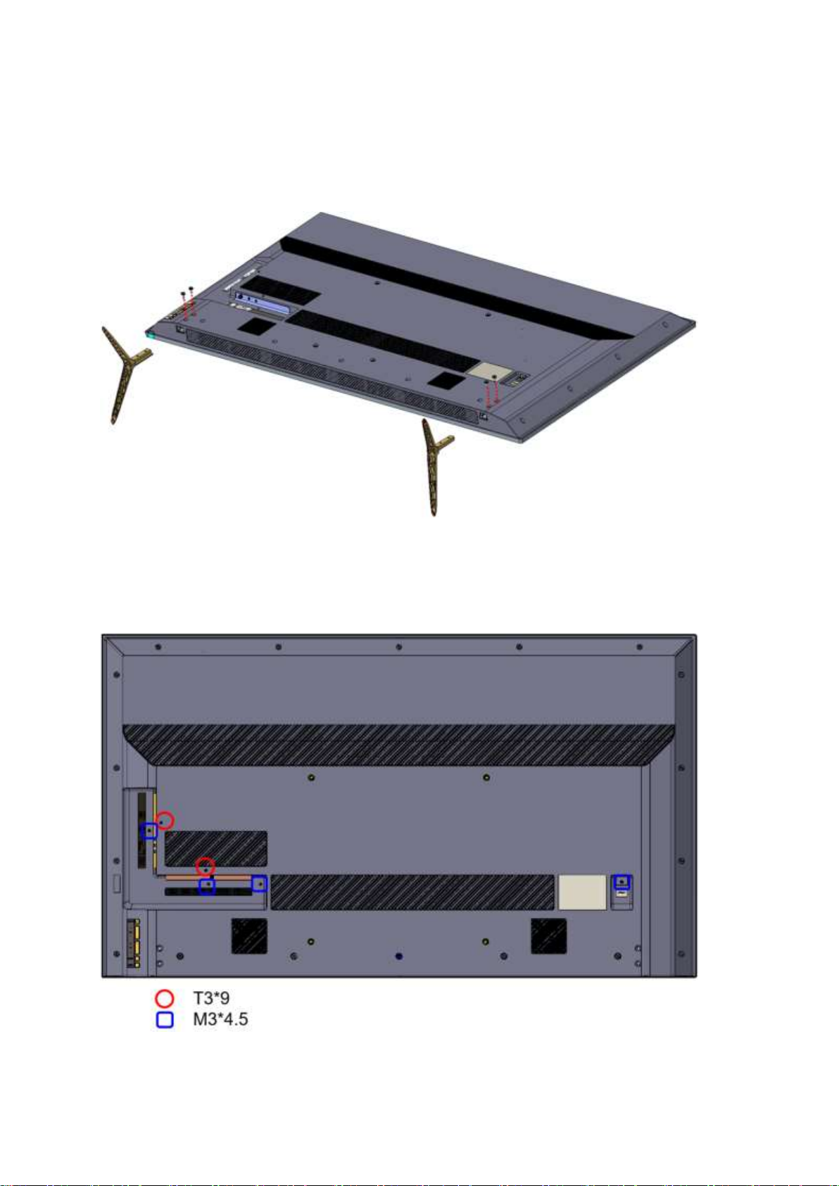
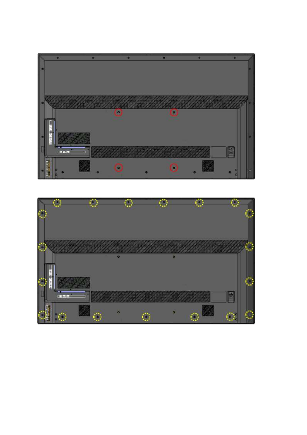
CHAPTER 2. Removing of Major Parts.......................................................4
[1] Removing of Major Parts .................................................................4
CHAPTER 3. ADJUSTMENT PROCEDURE...........................................17
[1] ADJUSTMENT PROCEDURE
[2] SERVICE MODE...............................................................................
[3] SOFTWARE UPGRADE PROCEDURE ..........................................
CHAPTER 4.TROUBLESHOOTING TABLE..............................................
[1] TROUBLESHOOTING TABLE........................................................
CHAPTER 5. MAJOR IC INFORMATIONS................................................
[1] MAJOR IC INFORMATIONS.......................................................33
CHAPTER 6.BLOCK DIAGRAM/WIRING DIAGRAM.........................43
[1] BLOCK DIAGRAM.......................................................................43
[2] POWER MANAGEMENT BLOCK DIAGRAM..........................44
[3] WIRING DIAGRAM .....................................................................44
CHAPTER 7.PRINTED WIRING DIAGRAM..............................................
[1] MAIN & LED UNIT PRINTED WIRING BOARD .....................45
[2] POWER UNIT PRINTED WIRING BOARD...................................
[3] KEY UNIT PRINTED WIRING BOARD.........................................
[4] IR UNIT PRINTED WIRING BOARD.........................................49
CHAPTER 8.SCHEMATIC DIAGRAM....................................................50
[1] MAIN SCHEMATIC DIAGRAM..................................................50
[2] POWER SCHEMATIC DIAGRAM ..................................................
[3] IR+LED+ALS DRIVER SCHEMATIC DIAGRAM ........................
[4] KEY SCHEMATIC DIAGRAM ........................................................
CHAPTER 9.PARTS GUIDE .....................................................................55
[1]SPARE PARTS LIST.......................................................................55
[2]CABINET PARTS...........................................................................57
[3]SUPPLIED ACCESSORIES...........................................................57
[4]PACKING PARTS...........................................................................58

1
CHAPTER 1. SPECIFICATIONS
[1] SPECIFICATIONS
ID
Panel
Size
70"
Backlight Type
D-LED
Resolution
3840 x 2160
Refresh Rate
60Hz
Response Time
8.5 ms
Color Gamut
97% REC709
Number of Colors
8-bit+FRC, 1.07B colors
Brightness (Typ.)
280nits
Contrast Ratio
4,000 : 1
Dynamic Contrast Ratio
200,000 : 1
Backlight Zones
-
Viewing Angle (H/V)
176°/176°
Picture
Local dimming
-
HDR
-
Film Mode (1080/24P)
-
Picture Mode
O
Color Temperature Adjustment
O
Video Noise reduction
O
Audio
Dolby Digital Decoder
MS11
Surround sound
-
Sound Output
20W (10W+10W)
TV SoC
RealTek RTD2991
Memory (DRAM / Flash)
1GB / 4GB
Broadcast System
ATSC / QAM
WiFi
802.11ac, Dual band, 2x2
Bluetooth
-
User Operation
Remote control
7-key Keypad
LED Indicator
Red / Green
Power Input
120~ Vac at 60 Hz
Power Consumption
200W (On), < 0.5W (Standby)

2
Terminal
RF Input
1
HDMI 1.4 Input / HDCP 1.4 (For 2K)
HDMI 2.0 Input / HDCP 2.2 (For 4K)
2 (HDMI 1 with ARC)
Video+L/R Input(φ3.5mm)
1
AV Input
1
RS232C
1
Headphone Output(φ3.5mm)
1
USB 2.0 (1.5A)
1
Ethernet
1
Software
Android TV
-
Play Store
-
YouTube
-
NetFlix
-
Google Cast
-
Mirroring
-
DLNA
-
USB MultiMedia
Video / Music / Photo
Eco
No signal off / No operation off
OSD Language
English / Spanish/ French
Software Update
Manual : USB / Network
Auto : Network
Mechanical / Package
VESA® Hole Pitch (WxH)
400x400 mm
Unit Dimension (w/o Stand) (WxHxD)
1568.5 x 904.9 x 72.3 mm
Unit Dimension (w/i Stand) (WxHxD)
1568.5 x 976.4 x 286.9 mm
Net Weight (w/o Stand)
25.2 kg
Net Weight (w/i Stand)
25.7 kg
Carton Structure
C Type
Carton Printing
Waterbased print
Carton Dimension (Outer,WxHxD)
1665 x 1021 x 200 mm
Gross Weight
34.5kg
Accessory
Power Cord
Detachable two prong (IEC)
Remote Control
IR, 37 buttons
Battery
AAA x 2
User Manual
E-manual (English, Spanish, French)
QSG
B/W print (English, Spanish, French)
Warranty Sheet
N/A (Combine into QSG)
Registration Card
-
Screw Bag (TV-Stand)
O

3
Certifications / Compliances
Safety/EMC
cULus, FCC, BETs-7
WiFi / Bluetooth
FCC/IC ID
Energy Saving
NRCan, CEC
[2] DIMENSIONS
Model
A
B
C
D
E
F
G
H
Bezel Width
T/R/L
Bottom
BM
(T/S/Bottom)
4T-B70CJ1U
1568.48
904.92
976.92
56.09
286.9
72.29
72
1390.07
14
22
0.8/0.8/2.5
TV screen size (Inches)
VESA-compatible wall bracket
(millimeters)(W*H)
Screw type
70"
400x400mm
Metric 6*12mm

4
CHAPTER 2. Removing of Major Parts
[1] Removing of Major Parts
STAND FEET REMOVAL:
1.- Remove the screw M5X14(2 per stand feet)

5
2.- Take the stand and slide out downwards from the TV set.
Note: Repeat operation in the 2nd stand
UNSCREW THE REAR COVER ASSY:
1.- Remove the 4 screw 3X4.5and 2 screw T3x9, around the I/O cover area and
AC-INLET.

6
2.- Remove the 4 VESAscrews M6X12
3.- Remove the 19 screws M3X8 at the rear cover area.

7
REMOVE THE REAR COVER ASSY:
1.-Use stand hole to pull rear cover and create GAP at corner area.
2.- Pull the Rear Cover from the bottom area and side area.
①The outer periphery of the front cover and CAB-B are fitted with hook , lift
while pushing slightly inward.
②Remove the key unit wire connector

8
3.- Finally use team-job to remove the Rear Cover completely.
REMOVE SPEAKERS, MAIN Board、Power Board、KEY Board、T-CON Board、
WIFI Board and Speakers.

9
•Speakers
1.- Disconnect the cable of speaker
2.- Slide out the stud
3.- Repeat operation in the 2nd speaker

10
•Main Board and WIFI board
1.- Disconnect the connection of the cable from the MB and WIFI board (Red
rectangle).
2.- Detach the I/O cover from the MB

11
3.- Remove 5 screws M3X6 in the main area (Redcircle).

12
4.- Unlock the hook (Red rectangle) and remove the WIFI board.
5.- Remove the screws (1pcs +PSW M3X8 [Red circle])and remove the WIFI
holder.

13
•PSU
1.-Disconnect the connection of the cable from the PSU (Red circle).
2.- To remove the PSU, unscrew 5 screws M3X6(Red circle)and 2 screws
M3X8(Blue circle)

14
•T-CON Board
1.- Disconnect the connection of the cable from the T-con (red rectangle)
2.- To remove the board, unscrew 6 screws M3X6( Yellow circle)
•Key pad
1.- Disconnect the connection of the cable from the key pad (red rectangle)

15
2.- To remove the key board, unscrew 2 screws T3X6 (Yellow rectangle)and 2
screws (red rectangle)
•IR Board
•1.- Disconnect the connection of the cable from the IR board (red rectangle)
•

16
2.
Pull open the hook of IR Lens
,
then take IR Board out.
WIRE DRESSING LAY-OUT

17
CHAPTER 3. ADJUSTMENT PROCEDURE
[1] ADJUSTMENT PROCEDURE
1. HOW TO START ADJUSTMENT PROCESS MODE
1)
WhileholdingdowntheINPUTandVolumeDOWNkeysatthesametime,plugintheACcordtoturnonthepower. (“K”
standing for inspection process mode is displayed on the upper left position of thescreen.)
2)
Press the Channel DOWN and Volume DOWN keys at the same time. (The adjustment process mode
screenappears.)
2. HOW TO EXITADJUSTMENT PROCESS MODE
1) To exit it, turn off the power using the Power switch or remote control.
3. REMOTE CONTROLLER KEY OPERATION OF DISPLAY IN ADJUSTMENT PROCESS MODE
1)
Keyoperation
Remote
controller key
Main
unit
key
Function
CH (
/
)
CH (
/
)
(Remote controller key)
Moving an item (line) by one (UP/DOWN)
(Main unit key)
Moving a page by one (UP/DOWN)
VOL (+/-)
VOL (+/-)
Changing a selected item setting.
(Remote controller ley) +1/-1
(Main unit key) +10/-10
Cursor (
)
-
Turning a page (PREVIOUS/NEXT)
Cursor (
)
-
Changing a selected line setting (+10/-10)
INPUT button on remote controller
INPUT button
Input source switching (toggle switching)
TV -> INPUT1(HDMI1) -> INPUT2(HDMI2) -> INPUT3(VIDEO)
ENTER
-
Execute a function.
2)
Description ofdisplay
Current selected input
Current page / Totalpages
Current color system
LCD panel size / Destination
1/7 [INFO]

4T-B70CJ1 TROUBLE SHOOTING 4 - 18
4. LIST OF ADJUSTMENT PROCESS MODE MENU
(*) The page number will be changed at the running change. For the number to be changed, please check ( ).
PAGE(*)
NUMBER
PAGE
TITLE
ITEM
FUNCTION
1/7
INFO
Main version
Main Software Version.
(Detail) Eel_ATSC_Pack**_v*.**(****)
V*.** : SW version
(****) : Boot version
SVN Number
Don’t care
PANEL Version
Don’t care
TEMP SENSOR
TEMP sensor (Thermistor) value every 200msec.
NORMALSTANDBT CAUSE
Cause of last Stand-By Operation.
(Detail) NONE / Remote control / Keyboard / RS232C / No signal off /
No operation off / Sleep timer
ERROR STANDBY CAUSE
Cause of last (up to 5) Error Protection Stand-By Operation and TIME.
(If the times have more than 5, the latest information should display at the
bottom.)
2/7
INIT
Factory Init
Initialization for factory settings
Panel Setting
LCD panel module information
Public Mode
Change of Enable/Disable access to Public Setting MENU.
Operation Acutime
Accumulate Time of TV-SET Operation.
RESET
Reset the Accumulate Time of TV-SET Operation.
3/7
WB ADJ
IN POINT LOW
Standard value Low (In AV MODE : STANDARD,MOVIE,GAME,USER,PC)
IN POINT HIGH
Standard value High
R LEVEL LOW
WB adjustment Point Low ,R adjustment value
G LEVEL LOW
WB adjustment Point Low ,G adjustment value
B LEVEL LOW
WB adjustment Point Low ,B adjustment value
R LEVEL HIGH
WB adjustment Point High ,R adjustment value
G LEVEL HIGH
WB adjustment Point High ,G adjustment value
B LEVEL HIGH
WB adjustment Point High ,B adjustment value
R LEVEL MAX
WB adjustment Point Max ,R adjustment value
G LEVEL MAX
WB adjustment Point Max ,G adjustment value
B LEVEL MAX
WB adjustment Point Max ,B adjustment value
ADJ DATA STORE
Update and Store all of gamma register value
RESET ADJUSTMENT
Reset default value above items and Adj-Flag
4/7
ETC
EEP CLEAR
Clear the EEPROM data to 0xFF.
STANDBYCAUSE RESET
Clear the STANDBY CAUSE history.
DESTINATION
Indicate the kind of Factory-Initialization command
L ERR RESET
Indicate the count of Lamp Error Protection. And Reset the counter
L ERR STOP
Lamp Error protection flag (Enable/Disable)
TEMP CAUTION
Setting for threshold level of High-Temp. caution (THRS1)
TEMP SHUTDOWN
Setting for threshold level of High-Temp. protection (THRS2)
5/7
PANEL
VCOM ADJ
V-COM adjustment value
TCON TEST PATTERN
Display the T-CON Test Pattern
TEST PATTERN
Display the Test Pattern.
Table of contents
Other Sharp HDTV manuals

Sharp
Sharp PN-UH861 User manual

Sharp
Sharp LC-6LX810E Owner's manual

Sharp
Sharp LC32CT2E Owner's manual

Sharp
Sharp LC60LE835UN User manual

Sharp
Sharp AQUOS PN-UH601 User manual

Sharp
Sharp PN-UH861 User guide

Sharp
Sharp 64LHP5000 User manual

Sharp
Sharp LC60LE830UN User manual

Sharp
Sharp ROKU LC-43LB371U User manual

Sharp
Sharp LC-55LB481U User manual