manuals.online logo
Brands
  1. Home
  2. •
  3. Brands
  4. •
  5. Sharp
  6. •
  7. Microwave Oven
  8. •
  9. Sharp R-4A55 User manual

Sharp R-4A55 User manual

R4A55
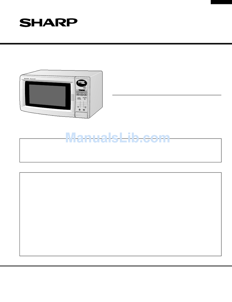
SHARP SERVICE MANUAL
MICROWAVE OVEN
MODEL R-4A55
in interests of user-safety the oven should be restored to its original condi-
t
, This is a supplimemental Service Manual For Model R-4A55. This model is Quite similar to Base Model R-4A53
(Refer No. is S7106R4A53PJZ). Use this supplimemental manual together with the Base Model Service Manual.
Refer to Base Model Service Manual for complete operation, service information, etc.
TABLE OF CONTENTS page
GENERAL IMPORTANT INFORMATION ...................................................................................................... 1
WARNING ...................................................................................................................................................... 1
RODUCT SPECIFICATIONS ......................................................................................................................... 2
APPEARANCE VIEW .................................................................................................................................... 3
SERVICING ................................................................................................................................................... 4
TEST PROCEDURE ...................................................................................................................................... 5
TOUCH CONTROL PANEL ........................................................................................................................... 9
COMPONENT REPLACEMENT AND ADJUSTMENT PROCEDURE ....................................................... .I4
WIRING DIAGRAM ...................................................................................................................................... 17
PICTORIAL DIAGRAM .................................................. ..1................................................................~ .......... 18
CONTROL PANEL CIRCUIT ...................................................................................................................... .I9
PRINTED WIRING BOA0 ............................................................................................................................ 20
PARTS LIST ................................................................................................................................................. 21
SHARP CORPORATION
SERVICE MANUAL
SHAFZP
MICROWAVE OVEN
R-4A55
GENERAL IMPORTANT INFORMATION
This Manual has been prepared to provide Sharp Corp. Service
engineers with Operation and Service Information.
It is recommended that service engineers carefully study the en-
tire text of this manual, so that they will be qualified to render sat-
isfactory customer service.
CAUTION
MICROWAVE RADIATION
Service engineers should not be exposed to the microwave en-
ergy which may radiate from the magnetron or other microwave
generating devices if it is improperly used or connected. All in-
put and output microwave connections, waveguides, flanges
andgaskets must be secured. Never operate the device without
a microwave energy absorbing load attached. Never look into
an open waveguide.
WARNING
Never operate the oven until the following points are ensured.
(A) The door is tightly closed.
(B) The door brackets and hinges are not defective.
(C) The door packing is not damaged.
(0) The door is not deformed or warped.
(E) There is not any other visible damage with the oven.
Servicing and repair work must be carried out only by trained
service engineers.
All the parts marked “*” on parts list are used at voltages more
than 250V.
Removal of the outer wrap gives access to potentials above
250V.
SHARP CORPORATION
OSAKA, JAPAN
R4A55R4A55
APPEARANCE VIEW
TEST PROCEDUREST PROCEDURE
PRODUCT SPECIFICATIONS
ITEM
Power Requirements 240 Volts
50 Hertz
DESCRIPTION
Power Consumption
Power Output
Case Dimensions
Single phase, 3 wire earthed
1.4 kW
750 watts nominal of RF microwave energy (AS 2895 1986)
900 watts (IEC-705-1 988 )
Operating frequency of 2450MHz
Width 550mm
Height 312mm
Depth 420mm
Cooking Cavity Dimensions Width 381 mm
Height 21 I mm
Depth 411 mm
Turntable diameter
Control Complement 360mm
Touch Control System
Clock ( 1:00 - 12:59)
Timer (0 - 99 minutes 99 secinds)
Microwave Power for Variable Cooking
Repetition Rate;
HIGH ...............................................Full power throughout the cooking time
MEDIUM HIGH ..................................................approx. 70% of Full Power
MEDIUM ...........*..*.............................................. approx. 50% of Full Power
MEDIUM LOW ....................................................approx. 30% of Full Power
LOW .................................*.....................*............ approx. 10% of Full Power
SERVE QUANTITY
INSTANT ACTION
AUTO COOK
EASY DEFROST
NUMBER pads
POWER LEVEL
MORE, LESS
STOP/CLEAR
Set Weight
AUTO START/CLOCK
INSTANT COOK/START
Approx. 17 kg
2
R4A55
APPEARANCE VIEW
8.Touch Control Panel
9.Digital readout
1O.Waveguide cover
11.Access cover for oven lamp replacement
12.Power supply cord
1.Ventilation openings
2.Oven lamp
3.Hinges
4.Safety door latches
5.See through door
6.Coupling
7.Door open button
TOUCH CONTROL PANEL
INSTANT ACTION PADS -
Press once to cook or reheat
8 popular menu.
AUTO COOK Chicken Reheat Ffoten
Press to select Auto Cook 1serve
Pieces Bevey;geSoup Dinner
1serve
mode.
AUTO COOK MENUS
NUMBER PADS
Press to enter
clock time, weight or quantity
of food, or to select the Auto
Cook menus.
Bacon Cy&es Fis~~~~ts
1 serve
.- Rice 8 Pasta Reheyt lW&sbie~
A
1
5seasonedRoast-
POWER LEVEL PAD-
Press to select microwave
power setting.
If not pressed, HIGH is auto-
matically selected.
STOP/CLEAR PAD
Press to clear during program
ming.
Press once to stop operation
of oven during cooking; press
twice to cancel cooking pro-
gramme.
- 2,3 or 4 SERVE QUANTITY
PADS
To cook two, three or four
serves, press required pad
prior to pressing the Instant
Action pad.
)I1u ,,q-q-qg
I
@q*y~ pj
Lp
I I I \
-MORE (A), LESS (r) PADS
Press to increase/decrease
the time in one minute incre-
ments during cooking or to
alter the doneness for the Al
Cook, Instant Action or Easy
Defrost modes.
- EASY DEFROST PAD
Press to defrost meat by en-
tering weight.
r INSTANT COOK/START
AUTO START/CLOCK PAD
Press to set clock or Auto
Start time. by 1 minute multiples each
time this pad is pressed dur-
ing cooking.
Press to start oven after set-
ting programmes.
3
WARNING TO SERVICE PERSONNEL
Microwave ovens contain circuitry capable of producing very high voltage and current, contact with any part of the
high voltage circuit will result in electrocution.
REMEMBER TO CHECK 3D
1) Disconnect the supply.
2) Door opened, and wedged open.
3) Discharge high voltage capacitor.
WARNING AGAINST THE CHARGE OF THE
HIGH-VOLTAGE CAPACITOR
The high-voltage capacitor remains charged
about 60 seconds after the oven has been
switched off. Wait for 60 seconds and then short-
circuit the connection of the high-voltage capaci-
tor (that is, of the connecting lead of the high-volt-
age rectifier) against the chassis with the use of
an insulated screwdriver.
Sharp recommend that wherever possible fault-find-
ing is carried out with the supply disconnected. It
may in, some cases, be necessary to connect the
supply after the outer case has been removed, in
this event carry out 3D checks and then disconnect
the leads to the primary of the power transformer.
Ensure that these leads remain isolated from other
components and the oven chassis. (Use insulation
tape if necessary.) When the testing is completed
carry out 3lJ checks and reconnect the leads to the
primary of the power transformer.
REMEMBER TO CHECK%
1) Reconnect all leads removed from components during
testing.
2) Replace the outer case (cabinet).
3) Reconnect the supply.
4) Run the oven. Check all functions.
Microwave ovens should not be run empty. To test for the
presence of microwave energy within a cavity, place a
cup of cold water on the oven turntable, close the door
and set the microwave timer for two (2) minutes. Set the
power level to HIGH and push the START button. When
the two minutes has elapsed (timer at zero) carefully
check that the water is now hot. If the water remains cold
carry out a checks and re-examine the connections to
the component being tested.
When all service work is completed, and the oven is fully assembled, the microwave power output should be
checked and microwave reakage test carried out
TEST PROCEDURES
PROCEDURE
LETTER COMPONENT TEST
A MAGNETRON TEST
NEVER TOUCH ANY PART IN THE CIRCUIT WITH YOUR HAND OR AN INSULATED TOOL ’
WHILE THE OVEN IS IN OPERATION.
CARRY OUT 3D CHECKS
Isolate the magnetron from the high voltage circuit by removing all leads connected to the filament
terminal.
To test for an open circuit filament use an ohmmeter to make a continuity test between the magnetron
filament terminals, the meter should show a reading of less than 1 ohm.
To test for a short circuit filament to anode condition, connect ohmmeter between one of the filament
terminals and the case of the magnetron (ground). This test should be indicated an infinite resistance.
If a low or zero resistance reading is obtained then the magnetron should be replaced.
MICROWAVE OUTPUT POWER (1 Litre water load)
The following test procedure should be carried out with the microwaveoven in a fully assembled condi-
tion (outer case fitted).Microwave output power from the magnetron can be measured by way of IEC
705, i.e. it can be measured by using water load how much it can be absorbed by the water load. To
measure the microwave output power in the microwave oven, the relation of calorie and watt is
used.When P(W) heating works for t(second), approximately P x t/4.187calorie is generated. On the
other hand, if the temperature of the water with V(ml) rises AT (“C) during this microwave heating
period, the calorie of thewater is V x AT
The formula is as follows;
Pxt/4.187=VxAT P(W)=4.187xVxAT/t
Our condition for the water load is as follows:
Room temperature ..........................around 20°C Power supply Voltage ...............Rated voltage
Water load ..... 1000 g Initial temperature ...........10%X Heating time ......................47sec.
P=9OxAT
Measuring condition:
1. Container
The water container must be a cylindrical borosilicate glass vessel having a maximum material
thickness of 3 mm and an outside diameter of approximately 190 mm.
2. Temperature of the oven and vessel
The oven and the empty vessel are at ambient temperature prior to the start of the test.
3. Temperature of the water
The initial temperature of the water is (10 + 2)X.
4. Select the initial and final water temperature so that the maximum difference between the final
water temperature and the ambient temperature is 5°C.
5. Select stirring devices and measuring instruments in order to minimize addition or removal of heat.
6. The graduation of the thermometer must be scaled by 0.X at minimum and an accurate ther-
mometer.
7. The water load must be (1000 + 5) g.
8. “t” is measured while the microwave generator is operating at full power. Magnetron filament heat-
up time is not included.
NOTE: The operation time of the microwave oven is “t + 2” sec. 2 sec. is magnetron filament heat-up
time.
Measuring method:
1. Measure the initial temperature of the water before the water is added to the vessel.
(Example: The initial temperature Tl = 11“C)
2. Add the 1 litre water to the vessel.
3 Place the load on the centre of the shelf.
5
TEST PROCEDURES
PROCEDURE
LElTER COMPONENT TEST
4. Operate the microwave oven at HIGH for the temperature of the water rises by a value A T of
(10 I!I2)“C.
5. Stir the water to equalize temperature throughout the vessel.
6. Measure the final water temperature.
(Example: The final temperature T2 = 21 “C)
7. Calculate the microwave power output P in watts from above formula.
Initial temperature ............................................................................................Tl = 11“C
Temperature after (47+2)= 49 sec. .................................................................T2 = 21 “C
Temperature difference Cold-Warm ...................................*....................*.... AT1 = 10°C
Measured output power
The equation is “P= 90 x AT” ................................................P= 90 x 10°C = 900 Watts
JUDGEMENT: The measured output power should be at least + 15 % of the rated output
power.
CAUTION: 1°C CORRESPONDS TO 90 WA-ITS. REPEAT MEASUREMENT IF THE POWER IS
INSUFFICIENT.
-- -
-- -
T2.C
Heat up for 49 sec.
MICROWAVE OUTPUT POWER (2 Litre water ioad)
The following test procedure should be carried out with the microwave oven in a fully assembled
condition (with outer case fitted).
Microwave output power from the magnetron can be measured by way of substitution, i.e. it can be
measured by using a water load how much it can be absorbed by the water load. To measure the
microwave output power in the microwave oven, the relation of calorie and watt is used.
On the other hand, if the temperature of the water with V(ml) rises AT (“C) during this microwave
heating period, the calorie of the water is V x AT.
The formulae is as follows;
P =8330xAT/t
Our condition for the water load is as follows:
Room temperature .................23& 2°C Power supply Voltage ..................Rated voltage.
Water load .......2000 ml Initial temperature .......23 + 1“C Heating time ....1min. 51 sec.
P = 75 x AT
Measuring method:
A) The two water containers must be prepared.
The water container must be one (1) litre beaker made of Pyrex glass and its diameter approxi-
mately 12cm.
B) Put the one (1) litre water into each beaker (Each beaker has one litre water). The initial tempera-
ture of the water should be 239°C.
C) Mark Tl on the one beaker and mark T2 on the other one. And stir the water and measure the
temperature of water the thermometer and note them. The graduation of the thermometer must be
scaled by 0.1 “C at minimum and an accurate mercury thermometer is recommended.
D) Place the two (2) beakers as touching each other in the centre of the oven cavity.
E) Set the timer to 1 minute and 51 seconds start the oven at HIGH.
6
R-4A55
TEST PROCEDURES
PROCEDURE
LETTER COMPONENT TEST
F) The time must be measured with stopwatch or wristwatch.
G) After 1 minute and 51 seconds, stop the oven by opening the door.
H) Put the two (2) beakers out of the oven cavity and measure the temperature of the water by stirring
the water with thermometer and note them.
Example
Initial temperature .......................................................*........................... Tl = 23°C T2 = 24°C
Temperature after 1 min. 51 set I
. *.......................................................... Tl = 33°C T2 = 34°C
Temperature difference Cold-Warm ...................................................ATI = 10°C ?,T2 = 10°C /
Mean temperature rise AT ..............................AT /
Measured output power = (AT1 31AT2) /2 = (1O”C+1O”C) / 2 = 10°C I
The equation is P= 75 x AT I
..............................................................
P= 75 x 10°C = 750 Watts /
NOTE: The measured output power should be at least i 15 % of the rated output power.
CAUTION: 1°C CORRESPONDS TO 75 WATTS.
REPEAT MEASUREMENT IF THE POWER IS INSUFFICIENT. I
II
d
x
- -
- -
-
- -
--
(Tl “C) (Tl “C)
Heat up for mtn. 5 set
II
Eli
7
--
--
--
--
(T2 “C)
J TOUCH CONTROL PANEL ASSEMBLY TEST
The touch control panel consists of circuits including semiconductors such as LSI, ICs, etc. Therefore,
unlike conventional microwave ovens, proper maintenance cannot be performed with only a voltmeter
and ohmmeter. In this service manual, the touch control panel assembly is divided into two units,
Control Unit and Key Unit, and troubleshooting by replacement is described according to the symp-
toms indicated.
1. Key Unit
The following symptoms indicate a defective key unit. Replace the key unit.
a) When touching the pads, a certain pad produces no signal at all.
b) When touching a number pad, two figures or more are displayed.
c) When touching the pads, sometimes a pad produces no signal.
2. Control Panel
The following symptoms indicate a defective control unit. Replacing the control unit.
2-1 In connection with pads.
a) When touching the pads. a certain group of pads do not produce a signal.
b) When touching the pads, no pads produce a signal.
2-2 In connection with indicators
a) At a certain digit, all or some segments do not light up.
b) At a certain digit, brightness is low.
c) Only one indicator does not light.
d) The corresponding segments of all digits do not light up; or they continue to light up.
e) Wrong figure appears.
f) A certain group of indicators do not light up.
g) The figure of all digits flicker.
2-3 Other possible problems caused by defective control unit.
a) Buzzer does not sound or continues to sound.
7
TEST PROCEDURES
PROCEDURE
LETTER COMPONENT TEST
b) Clock does not operate properly.
c) Cooking is not possible.
d) Proper temperature measurement is not obtained.
M RELAY TEST
1. CARRY OUT 3D CHECKS
2. Disconnect the leads from the primary of the power transformer. Make sure that the leads remain
isolated from other oven components and chassis. (Use insulation tape if necessary)
3. Close the door.
4. Reconnect the supply.
5. Check the voltage between Pin Numbers 3 and 5 of 4-pin connector (A) on the control unit with an
A.C. voltmeter. The meter should indicated 240 volts, if no check oven circuit.
6. RYl AND RY2 Test
These are operated by D.C. voltage. Check voltage at relay coil with a D.C. voltmeter during the
microwave cooking operation.
DC. voltage indicated ..........Defective relay.
DC. voltage not indicated ....Check diode which is connected to the relay coil. If diode is good,
control unit is defective.
RELAY SYMBOL OPERATIONAL
VOLTAGE CONNECTED COMPONENTS 1
RYl Approx. 26.5V.D.C. Oven lampnurntable motor/Cooling fan motor
RY2 Approx. 25.8V.D.C. Power transformer
N PROCEDURES TO BE TAKEN WHEN THE FOIL PAlTERN ON THE PRINTED WIRING BOARD
/PWB) IS OPEN.
To protect the electronic circuits, this model is provided with a fine foil pattern added to the primary on
the PWB, this foil pattern acts as a fuse. If the foil pattern is open, follow the troubleshooting guide
given below for repair.
Problem: POWER ON, indicator does not light up.
STEPS OCCURANCE CAUSE OR CORRECTION
1 The rated AC voltage is not present at Check supply voltage and oven power cord. Please use
POWER terminal of CPU connector (CN-A) term “Low voltage transformer” when refering to
transformer Tl .
The rated AC voltage is present at primary Low voltage transformer or secondary circuit defective.
side of low voltage transformer. Check and repair.
Only pattern at ‘a” is broken. *insert jumper wire Jl and solder. (CARRY OUT 3D
CHECKS BEFORE REPAIR)
Pattern at “a” and “b” are broken. ‘Insert the coil RCILF2003YAZZ between “c” and “d”.
(CARRY OUT 3D CHECKS BEFORE REPAIR)
is- i hi -- I I- . I i
b
NOTE:*At the time of these repairs, make a v
ual inspection of the varistor for burning
damage and test the T/C transformer
with an ohmmeter for the presence of
layer short-circuit (check primary coil re-
sistance). If any abnormal condition is
detected, replace the defective parts.
CARRY OUT @ CHECKS RYI c#-
8
TOUCH CONTROL PANEL ASSEMBLY
OUTLINE OF TOUCH CONTROL PANEL
The touch control section consists of the following unit as
shown in the touch control panel circuit
(1) Key Unit
(2) Control Unit
The principal functions of these units and the signals
communicated among them are explained below.
Key Unit
The key unit is composed of a matrix, signals generated
in the LSI are sent to the key unit through ROo - RO3, Rio
- R13. When a key pad is touched, a signal is completed
through the key unit and passed back to the LSI through
R23, R30 - R32 to perform the function that was
requested.
Control Unit
Control unit consists of LSI, power source circuit,
synchronizing signal circuit, ACL circuit, buzzer circuit
and indicator circuit.
1) LSI
This LSI controls the key strobe signal, relay driving
signal for oven function and indicator signal.
2) Power Source Circuit
This circuit for generates voltage necessary in the control
unit.
Symbol
VC
VP
VFl
VF2
Voltage
-5V
-29v
3Vac
Application
LSI(IC1)
Fluorescent display tube : Grid
and anode voltage
Filament of fluorescent display
tube
(VFl to VF2 voltage)
3) Synchronizing Signal Circuit
This power source synchronizing signal is available in
order to compose a basic standard time in the clock
circuit. It accompanies a very small error because it
works on commercial frequency.
4) ACL Circuit
A circuit to generat a signal which resets the LSI to the
initial state when power is supplied.
5) Buzzer Circuit
The buzzer responsive to signals from the LSI to emit
noticing sounds (key touch sound and completion
sound).
6) Door Sensing Switch
A switch to “tell” the LSI if the door is open or closed.
7) Relay Circuit
To drive the magnetron, fan motor, turntable motor and
light the oven lamp.
8) Indicator Circuit
Indicator element is a Fluorescent Display.
Basically, a Fluorescent Display is a triode having a
cathode, a grid and an anode. Usually, the cathode of a
Fluorescent Display is directly heated and the filament
serves as cathode.
The Fluorescent Display has 6-digits, 13segments are
used for displaying figures.
R-4A55
DESCRIPTION OF LSI
LSI(IZA430DR)
The I/O signal of the LSI(IZA430DR) is detailed in the following table.
rPIN NO. DESCRIPTION
I
c
I
I
i
1
!
1
1
I
i
I
!
1
I
[
I
I
!-
I
~
i
Diqit selection signal. I
Refer to the touch control panel circuit about the relation between signals and digits. ’
Normally, one pulse is output in every synchronized signal period, and input to the
grid of the fluorescent dispaly.
Dll OUT Seqment data siqnals.
Refer to the touch control panel circuit for the relationship between signals and
indicators.Normally, one pulse is output in every synchronized signal period, and
input to the anode of the fluorescent display.
i
2
3 TGl OUT Siqnal to sound buzzer.
A: key touch sound(OJ2sec.).
B: Completion sound(2.4sec.).
I
Vdisp 1 IN Anode (seqment) of Fluorescent Displav illumination voltaqe: -29V
Vp voltage of power source circuit input.
ROo OUT Seqment data siqnal.
Signal similar to Dl 1.
Kev strobe siqnal.
Signal applied to touch-key section. A pulse signal is input to R2s,R30-R32 terminal /
while one of Gl line keys on key matrix is touched
6 Seqment data siqnal.
Signal similar to Dl 1.
Kev strobe siqnal.
Signal applied to touch-key section. A pulse signal is input to R2s,R30-R32 terminal
while one of G2 line keys on key matrix is touched.
ROI OUT
/
l-
7 R02 ,i OUT Seament data siqnal.
Signal similar to Dll.
Kev strobe siqnal.
Signal applied to touch-key section. A pulse signal is input to R2s,R30-R32 terminal
while one of G3 line keys on key matrix is touched. I
a Seament data siqnal.
Signal similar to Dl 1.
Key strobe siqnal.
Signal applied to touch-key section. A pulse signal is input to R2s,R30-R32 terminal
while one of G4 line keys on key matrix is touched.
9 Seqment data sianal.
Signal similar to Dl 1.
Kev strobe siqnal.
Signal applied to touch-key section. A pulse signal is input to R2s,R30-R32 terminal
while one of G5 line keys on key matrix is touched.
RIO OUT
Segment data sianal.
Signal similar to Dll.
Key strobe siqnal.
1
Signal applied to touch-key section. A pulse signal is input to R2s,R30-R32 terminal
while one of G6 line keys on key matrix is touched.
10
PIN NO. 1SIGNAL / I/O DESCRIPTION
11 R12 OUT Seqment data siqnal.
Signal similar to Dl I.
Kev strobe siqnal.
Signal applied to touch-key section. A pulse signal is input to R2s,R30-R32 terminal
while one of G7 line keys on key matrix is touched.
‘2 RI3 OUT Seqment data siqnal.
Signal similar to Dll.
Kev strobe siqnal.
Signal applied to touch-key section. A pulse signal is input to R2s,R30-R32 terminal
while one of G8 line keys on key matrix is touched.
13-15 R2o-R22 OUT Seqment data siqnal.
Signal similar to Dl 1.
I6 R23 IN Siqnal cominq from touch kev.
When either one of G9 line keys on key matrix is touched, a corresponding signal
out of ROo-ROs, RIO-Rls will be input into R23. When no key is touched, the signal
is held at “L” level.
IN Siqnal cominq from touch kev.
When either one of GIO line keys on key matrix is touched, a corresponding signal
will be input into R30.
IN Siqnal cominq from touch kev.
When either one of Gl 1 line keys on key matrix is touched, a corresponding signal
will be input into R31.
IN Siqnal cominq from touch kev.
When either one of G12 line keys on key matrix is touched, a corresponding signal
will be input into R32.
I2ojNTl1IN1
Siqnal svnchronized with commercial source frequencv(5OHz).
This is basic timing for time processing of LSI.
1 21 1GND 1 IN 1 Power source voltaqe: -5V
VC voltage of power source circuit input.
22 AVCC IN Connected to GND.
23-24 ANO-AN1 IN
25 AN2 IN
Connected to VC.
Terminal not used.
26 AN3 IN Input siqnal which communicates the door open/close information to LSI.
Door closed; “H” level signal.
Door opened; “L” level signal.
27 AVSS IN
28 RESET IN
Connected to VC.
Auto clear terminal.
Signal is input to reset the LSI to the initial state when power is supplied. Temporar-
ily set to “H” level the moment power is supplied, at this time the LSI is set. Thereaf-
ter set at “L” level.
29 TEST IN Connected to GND.
11
7
PIN NO. SIGNAL I/O DESCRIPTION
30 OSCI IN Internal clock oscillation frequencv input settinq.
The internal clock frequency is set by inserting the ceramic filter oscillation circuit
with respect to OSCI terminal.
I3’ IOSC2IOUT 1 Internal clock oscillation frequency control outnut.
iOutput to control oscillation input of OSC2.
j 32 Power source voltaae input terminal.
1‘cc 1 lN 1 Connected to GND. -
33 DO OUT Terminal not used.
’ 34 Dl OUT Maqnetron hiqh-voltaqe circuit drivinct sianal.
To turn on and off the cook relay. In high operation, the signals holds “H” level
during microwave cooking and “L” level while not cooking. In other cooking modes
(MED HIGH, MED,MED LOW,LOW) the signal turns to “H” level and “L” level in
) repetition according to the power level.
!
35 D2 j OUT / Terminal not used. I
1 36 D3 OUT ’ Oven lamp,turntable motor and coolino fan motor drivinq sional. (Square
Waveform: 45Hz)
To turn on and off the control relay. The pulse signal (45Hz) is delivered to the
control relay driving circuit and cook relay control circuit.
37 04 OUT / Seqment data signal.
1 Signal similar to Dll.
38-42 D5-D9 OUT Diqit selection siqnal.
Signal similar to DIO.
12
SERVICING
1Precautions for Handling Electronic Components
This unit uses CMOS LSI in the integral part of the
circuits. When handling these parts, the following
precautions should be strictly followed. CMOS LSI have
extremely high impedance at its input and output termi-
nals. For this reason, it is easily influenced by the sur-
rounding high voltage power source, static electricity
charge in clothes, etc, and sometimes it is not fully
protected by the built-in protection circuit.
In order to protect CMOS LSL
1) When storing and transporting, thoroughly wrap them
in aluminum foil. Also wrap all PW boards containing
them in aluminium foil.
2) When soldering, ground the technician as shown in
the figure and use a grounded soldering iron and work
table.
ohm
2. Shapes of Electronic Components
Tmncichr
I I UI lc11QL”,
- [
ITAl 14ES;
i’; U DTA143ES I
DTC143ES
DTD143ES
3. Servicing of Touch Control Panel
We describe the procedures to permit servicing of the
touch control panel of the microwave oven and the
precautions you must take when doing so. To perform
the servicing, power to the touch control panel is avail-
able either from the power line of the oven itself or from
an external power source.
(1)Servicing the touch control panel with power
supply from the oven proper:
CAUTION:
THE HIGH VOLTAGE TRANSFORMER OF THE
MICROWAVE OVEN IS STILL ALIVE
TO GIVE YOU DANGER DURING SERVICNG:
Therefore, when checking the performance of the
touch control panel, put the outer cabinet on the oven
to avoid touching the high voltage transformer, or
unplug the primary terminal (connector) of the high
voltage transformer to turn it off; the end of such
connector must be insulated with an insulating tape.
After servicing, be sure to replace the leads to their
original locations.
A.On some models, the power supply cord between the
touch control panel and the oven itself is so short that
the two can’t be separated. For those models, check
and repair all the controls (sensor-related ones in-
cluded) of the touch control panel while keeping it
connected to the oven.
B.On some models, the power supply cord between the
touch control panel and the oven proper is long
enough
that they may be separated from each other. For
those models, therefore, it is possible to check and
repair the controls of the touch control panel while
keeping it apart from the oven proper; in this case you
must short both ends of the door sensing switch (on
PWB) of the touch control panel with a jumper, which
brings about an operational state that is equivalent to
the oven door being closed. As for the sensor-related
controls of the touch control panel, checking them is
possible if dummy resistor(s) with resistance equal to
that of the controls are used.
(2)Servicing the touch control panel with power
supply from an external power source:
Disconnect the touch control panel completely from
the oven proper, and short both ends of the door
sensing switch (on PWB) of the touch control
panel,which brings about an operational state that is
equivalent to the oven door being closed. Connect an
external power source to the power input terminal of
the touch control panel, then it is possible to check
and repair the controls of the touch control panel; it is
also possible to check the sensor related controls of
the touch control panel by using the dummy
resistor(s).
4. Servicing Tools
Tools required to service the touch control panel assem-
bly.
l)Soldering iron: 30W
(It is recommended to use a soldering iron with a
grounding terminal.)
2)Oscilloscope:Single beam, frequency range: DC-
10MHz type or more advanced model.
3)Others:Hand tools
5. Other Precautions
l)Before turning on the power source of the control unit,
remove the aluminum foil applied for preventing static
electricity.
2)Connect the connector of the key unit to the control
unit being sure that the lead wires are not twisted.
3)After aluminum foil is removed, be careful that abnor-
mal voltage due to static electricity etc. is not applied
to the input or output terminals.
4)Attach connectors, electrolytic capacitors, etc. to
PWB, making sure that all connections are tight.
5)Be sure to use specified components where high
precision is required
13
- . .
R4A55
COMPONENT REPLACEMENT AND ADJUSTMENT PROCEDURE
WARNING: AVOID POSSIBLE EXPOSURE TO MICROWAVE ENERGY. PLEASE FOLLOW THE INSTRUC-
TIONS BELOW .BRBEFORE OPERATING THE OVEN. I
1. CARRY OUT 3D CHECKS.
2. Make sure that a definite “click” can be heard when the
door is unlatched. (Hold the door in a closed position
with one hand, then push the door open button with the
other, this causes the latch heads to rise, it is then pos-
sible to hear a “click” as the door switches operate.)
3. Visually check the door and cavity face plate for dam-
age (dents, cracks, signs of arcing etc.).
2. Door hinge, support or latch hook is damaged.
3. The door gasket or seal is damaged.
4. The door is bent or warped.
5. There are defective parts in the door interlock system.
6. There are defective parts in the microwave generating
and transmission assembly.
7. There is visible damage to the oven.
Do not operate the oven:
1. Without the RF gasket (Magnetron).
2. If the wave guide or oven cavity are not intact.
3. If the door is not closed.
4. If the outer case (cabinet) is not fitted.
Carry out any remedial work that is necessary before oper-
ating the oven.
Do not operate the oven if any of the following conditions
exist
1. Door does not close firmly.
Please refer to ‘OVEN PARTS, CABINET PARTS, DOOR PARTS’, when carrying out any of the following removal proce-
dures:
1.
2.
3.
4.
CARRY OUT aCHECKS
Remove the fan motor assembly from the oven refer-
ring to “FAN MOTOR REPLACEMENT”.
Disconnect the filament lead of the power transformer
from high voltage capacitor.
Disconnect the filament lead of the power transformer
from the magnetron.
1.
2.
3.
4.
TURNTABLE MOTOR REMOVAL
Disconnect oven from power supply. 5.
Remove turntable and roller stay from oven cavity. Remove two (2) screws holding turntable motor to oven
cavity bottom side and remove the turntable motor.
Remove one (1) screw holding the turntable motor 6.
cover to bottom plate and remove the cover. Now the turntable motor is free. At this time, O-ring and
washer is removed. Do not loose them.
Disconnect wire leads from turntable motor.
1.
2.
OVEN LAMP AND LAMP SOCKET REMOVAL
CARRY OUT =CHECKS
3.
4.
5.
6.
Remove the snap of the wire tie holding the wire leads
to the lamp socket from the hole of the oven cavity.
Remove the one (1) screw holding the magnetron air
guide to the oven cavity and remove it.
Lift up the tab holding the oven lamp socket.
Remove the oven lamp socket.
Pull the wire leads from the oven lamp socket by push-
ing the terminal hole of the oven lamp socket with the
flat type small screw driver.
5. Now, the oven lamp socket is free.
POWER TRANSFORMER REMOVAL
5. Disconnect the high voltage wire of H.V. rectifier as-
sembly from the power transformer.
6. Remove the one (1) screw from under side and the two
(2) screws from upper side holding the transformer to
bottom plate.
7. Remove the transformer.
screw driver
14
FAN MOTOR REPLACEMENT
REMOVAL
1. CARRY OUT 3D CHECKS.
2. Disconnect the wire leads from the fan motor.
3. Disconnect the H.V. wire A and the filament
lead(longer one) of the power transformer from the
magnetron.
4. Release the H.V. wire A and filament lead from the
holes in the fan duct.
5. Remove the one (1) screw holding the magnetron air
guide to the oven cabity and remove it.
6. Release the tabs of the fan duct from the holes in the
bottom platet and the back plate of the oven cavity.
7. Release the main wire harness from the hole in the fan
duct.
8. Now, the fan motor assembly is free.
9. Remove the fan blade from the fan motor shaft accord-
ing the following procedure.
1) Hold the edge of the rotor of the fan motor by using a
pair of groove joint pliers.
CAUTION:
Make sure that any pieces do not enter the gap be-
tween the rotor and the stator of the fan motor.
Because the rotor is easy to be shaven by pliers
and metal pieces may be produced.
Do not touch the pliers to the coil of the fan motor
because the coil may be cut or injured.
Do not transform the bracket by touching with the
pliers.
Remove the fan blade from the shaft of the fan motor
by pulling and rotating the fan blade with your hand.
Now, the fan blade will be free.
roove jomt pliers
Rear view
CAUTION:
* Do not use this removed fan blade again.
Because the hole(for shaft) of it may become big-
ger than a standard one.
1O.Remove the two(2) screws and nuts holding the fan
motor to the fan duct.
11.Now, the fan motor is free.
INSTALLATION
1. Install the fan motor to the fan duct with the two(2)
screws and nuts.
2. Install the fan blade to the fan motor shaft according the
following procedure.
1) Hold the center of the bracket which supports the shaft
of the fan motor on the flat table.
2) Apply the screw lock tight into the hole(for shaft) of the
fan blade.
3) Install the fan blade to the shaft of fan motor by pushing
the fan blade with a small, light weight, ball peen ham-
mer or rubber mallet.
CAUTION:
*
*
l
3.
4.
5.
6.
Do not hit the fan blade strongly when installed be-
cause the bracket may be transformed.
Make sure that the fan blade rotates smooth after
installed.
Make sure that the axis of the shaft is not slanted.
Insert the tabs of the fan duct into the hole in the bottom
plate right and the back plate of the oven cavity.
Install the fan duct to the oven cavity certainly.
Re-install magnetron air guide to the oven cavity with
the one(l) screw.
Connect the wire leads to the fan motor and magne-
tron, referring to the pictorial diagram.
rk-
Shaft
Axt ese are the posrtlon
Side view
SEALER FILM Sealer film
\ Backing film
Removal
1. Tear the sealer film from the door panel.
2. NOW,the sealer film is free.
Installation
1. Put the adhesive tape on the backing film of the sealer
film as shown in illustration.
2. Tear the backing film by pulling the adhesive tape.
3. Put the pasted side of the sealer film on the door panel.
15
Ff4A55
POWER SUPPLY CORD REPLACEMENT
Removal 5. Wind the conductors of Blue and White wires each
1. CARRY OUT 3D CHECKS. other.
2. Disconnect the brown wire of the power supply cord 6. Insert the stripped wire leads into the connector CE-
from the fuse holder. 230.
3. Remove the connector CE-230 by cutting the con- 7. Clamp the connector CE-230 with the correct tool
netted wire leads to it.
4. Remove the single (1) screw holding the green/yellow
wire of the power supply cord to the oven cavity.
5. Remove the single (1) screw holding the cord anchor-
age to the oven cavity.
tightly.
Cord anchorage
6. Remove the power supply cord from the oven.
Re-install
1. Insert the power supply cord into the cord anchorages.
2. Connect the brown wire of the power supply cord to the
fuse holder.
3. Install the green/yellow wire of the power supply cord to
the oven cavity with the single (1) screw tightly.
4. Make sure that the blue wire and the white wire are
stripped for 15mm length.
Blue wire lead of
power supply cord
White wire’
+@/ I
Green/Yellow wire Connector
CE230
Wire lead of the
main wire harness Connector CE-230
Power supply
cord
UPPER LATCH SWITCH, LOWER LATCH SWITCHES, STOP SWITCH AND MONITOR SWITCH REMOVAL
1. CARRY OUT 3D CHECKS.
2. Remove the air duct from the oven cavity.
3. Disconnect the leads from all switches.
4. Remove the two (2) screws holding the latch hook to
the oven cavity.
5. Remove the latch hook.
6. Push the retaining tab slightly and remove the switch.
16
,PwP3t-:<
. . . . 0
&g ;;
0 xx 0
3Mti
=+g 52
U I”o,F;1
” c-1
30 +3; ‘I ‘!
3
oyt+ c
x ,< * :1
i !i lq % 11.
;;($k” 0 g
j$ ; ;;
3;;’ lc;:1
II’ z
5 $
G
G
2
-i
rdklz
* * 0
;7x?
p.
4
*p u
‘U0 ti
;:2 ‘2
$pg 5
c 0 .’
.I
g q 3
9
x ti
m z
v
5
r-J-4
240V-50Hz
BLU BRN
f-7ciKil riiq FUSE
MBA
II}-+=+
EARTH
BLU BRN
(NEUTRAL] jiiq FUSE
M8A
THERMAL
CUT-OUT
TEMP.
FUSE TEMP.
FUSE
2ND
LATCH
SWITCH
CONTROL
UNIT RY-1 A,’
A-----
A3 A5
I-----” -
rh I - --r
n
9’
;i;
0 1ST
L LA I-CH
b
SWITCt
L
Q %H
P SWlTCt
0
5
t?
z 5
ii
S
8
8
x
I.
ri
I ----_ I
Chkl LIATnn
- I
TURNTABLE MOTOR
\
MONITOR SWITCH
---------I I
POWER TRANSFORMER POWER TRANSFORMER
li”l n
CAPACITOR
1.13vF
AC2100V r
-
iT
i -I
RECTIFIER L---1
MAGNETRON RECTIFIER ---
MAGNETRON
- - f 3 6 __-
B
C
D,
E
Fi !
I
Gj
I
--.
I
H /
/
1
1 2 3 4 5 6
18
&%A55
1 I 2 3 / 4 / 5 I 6
1‘1,’ !I$ iG”z/qi j I I i 1
LA=-llll~I,&++~ / / 1
“I- I I I
1 -- d
1 m
- l-1
Pr
&x2
8%
awlL.2
7-+
4
1 ! 2 I 3 4 I 5 / I
6
19
- . _. .- ._

Other Sharp Microwave Oven manuals

Sharp R-969IN User manual

Sharp

Sharp R-969IN User manual

Sharp R-420EK User manual

Sharp

Sharp R-420EK User manual

Sharp R-240D Use and care manual

Sharp

Sharp R-240D Use and care manual

Sharp Carousel R-1405, Carousel R-1406 User manual

Sharp

Sharp Carousel R-1405, Carousel R-1406 User manual

Sharp R-15AM User manual

Sharp

Sharp R-15AM User manual

Sharp R-420DK User manual

Sharp

Sharp R-420DK User manual

Sharp R-480C User manual

Sharp

Sharp R-480C User manual

Sharp R-2371K User manual

Sharp

Sharp R-2371K User manual

Sharp R-84ST User manual

Sharp

Sharp R-84ST User manual

Sharp R-21LTF - Oven Microwave 1000 W User manual

Sharp

Sharp R-21LTF - Oven Microwave 1000 W User manual

Sharp Carousel R-350J User manual

Sharp

Sharp Carousel R-350J User manual

Sharp 203H User manual

Sharp

Sharp 203H User manual

Sharp R-7771L User manual

Sharp

Sharp R-7771L User manual

Sharp R-959(SL)M-AA Instruction Manual

Sharp

Sharp R-959(SL)M-AA Instruction Manual

Sharp R-25AM User manual

Sharp

Sharp R-25AM User manual

Sharp R-742W User manual

Sharp

Sharp R-742W User manual

Sharp KB6021MW - 24 Insight Pro Microwave Drawer Assembly instructions

Sharp

Sharp KB6021MW - 24 Insight Pro Microwave Drawer Assembly instructions

Sharp YC-MG01U-S User manual

Sharp

Sharp YC-MG01U-S User manual

Sharp SKCD24U0GS User manual

Sharp

Sharp SKCD24U0GS User manual

Sharp SMC1162HS User manual

Sharp

Sharp SMC1162HS User manual

Sharp YC-MG252A User manual

Sharp

Sharp YC-MG252A User manual

Sharp KB6002LS - 1.0 cu. Ft. Microwave Drawer Assembly instructions

Sharp

Sharp KB6002LS - 1.0 cu. Ft. Microwave Drawer Assembly instructions

Sharp R-208 Instruction Manual

Sharp

Sharp R-208 Instruction Manual

Sharp R-771 OE User manual

Sharp

Sharp R-771 OE User manual

Popular Microwave Oven manuals by other brands

Samsung MW81Z Owner's instructions

Samsung

Samsung MW81Z Owner's instructions

VOSS MOA4226 Instruction book

VOSS

VOSS MOA4226 Instruction book

GE JES942 owner's manual

GE

GE JES942 owner's manual

Bartscher 10250M manual

Bartscher

Bartscher 10250M manual

Defy DMO 356 owner's manual

Defy

Defy DMO 356 owner's manual

Whirlpool RJM 7600 Use and care guide

Whirlpool

Whirlpool RJM 7600 Use and care guide

CAFÉ CVM519 owner's manual

CAFÉ

CAFÉ CVM519 owner's manual

Samsung ME71M Owner's instructions & cooking guide

Samsung

Samsung ME71M Owner's instructions & cooking guide

Merrychef 402s user guide

Merrychef

Merrychef 402s user guide

Daewoo KOR-63B50S Service manual

Daewoo

Daewoo KOR-63B50S Service manual

Samsung MC28H5013AW Instructions & cooking guide

Samsung

Samsung MC28H5013AW Instructions & cooking guide

Saivod MSGE-2819S manual

Saivod

Saivod MSGE-2819S manual

Samsung MS28F303T series user manual

Samsung

Samsung MS28F303T series user manual

Maytag MMV6178 Use and care guide

Maytag

Maytag MMV6178 Use and care guide

GE Appliances JVM1950 installation instructions

GE

GE Appliances JVM1950 installation instructions

Whirlpool YMH2175XS Use & care guide

Whirlpool

Whirlpool YMH2175XS Use & care guide

Rasonic RMO-M207MX Operation manual

Rasonic

Rasonic RMO-M207MX Operation manual

KitchenAid KCMS2055SSS0 parts list

KitchenAid

KitchenAid KCMS2055SSS0 parts list

manuals.online logo
manuals.online logoBrands
  • About & Mission
  • Contact us
  • Privacy Policy
  • Terms and Conditions

Copyright 2025 Manuals.Online. All Rights Reserved.