Shearwater Teric User manual

Operating Instructions

Operating Instructions
Page 2 RevA
Table of Contents
Table of Contents���������������������������������������������������������� 2
Conventions Used in this Manual ����������������������������������������������� 4
1. Introduction.....................................................5
1�1� Notes on this manual���������������������������������������������������������������� 6
1�2� Modes Covered by this Manual�������������������������������������������� 6
2. Basic Operation..............................................7
2�1� Turning On ������������������������������������������������������������������������������������7
2�2� Buttons����������������������������������������������������������������������������������������� 8
2�3� Changing between Modes���������������������������������������������������� 9
2�4� Owner Information Screen��������������������������������������������������� 9
2�5� Function Button������������������������������������������������������������������������ 9
3. Dive Mode Interface.....................................10
3�1� Default Dive Setup�������������������������������������������������������������������10
3�2� Dive Mode Differentiation����������������������������������������������������10
3�3� Main Screen Layout����������������������������������������������������������������� 11
3�4� Detailed Descriptions������������������������������������������������������������ 12
3�5� Info Screens�������������������������������������������������������������������������������16
3�6� Info Screen Descriptions������������������������������������������������������ 17
3�7� Home Screen Customization ���������������������������������������������� 21
3�8� Alerts ������������������������������������������������������������������������������������������ 22
4. Safety and Decompression Stops............ 24
4�1� Safety Stops������������������������������������������������������������������������������ 24
4�2� Decompression Stops ���������������������������������������������������������� 25
5. Decompression and Gradient Factors ..... 26
5�1� Decompression Information Accuracy ��������������������������� 27
6. Example Dives ............................................. 28
6�1� OC Rec Example Dive �����������������������������������������������������������28
6�2� OC Tec Example Dive�����������������������������������������������������������29
OC Tec Example Dive (cont�)�����������������������������������������������������30
6�3� CC Example Dive ��������������������������������������������������������������������31
CC Example Dive (cont�) ������������������������������������������������������������� 32
CC Example Dive (cont�) �������������������������������������������������������������33
6�4� Gauge Mode ����������������������������������������������������������������������������34
7. Freedive Mode ............................................. 35
7�1� Default Freediving Layout���������������������������������������������������� 35
7�2� Freediving Info Screens �������������������������������������������������������36
7�3� Freediving Sets �����������������������������������������������������������������������36
8. Dive Tools ..................................................... 38
8�1� Compass�������������������������������������������������������������������������������������38
8�2� Tag Log ������������������������������������������������������������������������������������� 40
8�3� Reset Average Depth ���������������������������������������������������������� 40
8�4� Test Alert���������������������������������������������������������������������������������� 40
8�5� Deco Planner ����������������������������������������������������������������������������41
8�6� NDL Planner�����������������������������������������������������������������������������43
9. Air Integration (AI).....................................44
9�1� What is AI? ��������������������������������������������������������������������������������44
9�2� Basic AI Setup�������������������������������������������������������������������������45
9�3� AI Displays��������������������������������������������������������������������������������48
9�4� Using Multiple Transmitters �����������������������������������������������50
9�5� SAC calculations���������������������������������������������������������������������� 51
9�6� GTR calculations �������������������������������������������������������������������� 52
10. Watch Mode ............................................... 53
10�1� Date And Time������������������������������������������������������������������������53
10�2� Watch Tools����������������������������������������������������������������������������53
10�3� Watch Face Colors��������������������������������������������������������������� 55
11. Menus ........................................................... 56
11�1� Main Menu����������������������������������������������������������������������������������56
12. Settings Reference.................................... 63
12�1� Dive Settings Menu ���������������������������������������������������������������63
12�2� Deco Menu ������������������������������������������������������������������������������68
12�3� Gases�����������������������������������������������������������������������������������������69
12�4� Set Points ��������������������������������������������������������������������������������69
12�5� AI�������������������������������������������������������������������������������������������������70
12�6� Compass ���������������������������������������������������������������������������������� 71
12�7� Display��������������������������������������������������������������������������������������� 72
12�8� Watch���������������������������������������������������������������������������������������� 74
12�9� General ������������������������������������������������������������������������������������� 75
13. Firmware Update and Log Download .... 76
13�1� Shearwater Cloud Desktop������������������������������������������������76
13�2� Shearwater Cloud Mobile �������������������������������������������������� 78

Operating Instructions
Page 3 RevA
14. Teric Strap .................................................. 79
15. Charging ..................................................... 79
16. Troubleshooting ......................................... 81
16�1� Warnings and Information Displays ��������������������������������81
16�2� AI Connection problems���������������������������������������������������� 82
17. Storage and Maintenance......................... 83
17�1� Transmitter Battery Replacement������������������������������������83
18. Servicing ..................................................... 83
Glossary ............................................................ 83
Teric Specifications ........................................ 84
Teric Specifications (cont.) ........................... 84
AI Transmitter Specifications ....................... 85
FCC Warning������������������������������������������������������������������������������������85

Operating Instructions
Page 4 RevA
Conventions Used in this Manual
These conventions are used to highlight important
information:
INFORMATION
Information boxes contain useful tips
for getting the most out of your Teric.
CAUTION
Caution boxes contain important
instructions on operating the Teric.
WARNING
Warning boxes contain critical
information that may affect your
personal safety.
This computer has bugs. Although we haven’t found them all yet,
they are there. It is certain that there are things that this computer
does that either we didn’t think about, or planned for it to do
something different. Never risk your life on only one source of
information. Use a second computer or tables. If you choose to
make riskier dives, obtain the proper training and work up to them
slowly to gain experience.
This computer will fail. It is not whether it will fail but when it will
fail. Do not depend on it. Always have a plan on how to handle
failures. Automatic systems are no substitute for knowledge and
training.
No technology will keep you alive. Knowledge, skill, and practiced
procedures are your best defense (except for not doing the dive, of
course).
WARNING
This computer is capable of calculating deco stop requirements. These
calculations are at best a guess of the real physiological decompression
requirements. Dives requiring staged decompression are substantially
more risky than dives that stay well within no-stop limits.
Diving with rebreathers and/or diving mixed gases and/or performing
staged decompression dives and/or diving in overhead environments
greatly increases the risk associated with of scuba diving.
YOU REALLY ARE RISKING YOUR LIFE
WITH THIS ACTIVITY.
DANGER
Operating Instructions
Page 5 RevA
Features
• Vivid full color 1.39” AMOLED display
• Rugged stainless steel bezel and sapphire crystal
• Crush proof to 650ft /200m
• 5 independently configurable diving modes
• 2 customizable layouts for every dive mode
• 5 customizable gases in every SCUBA mode
• Any combination of Oxygen, Nitrogen and Helium
(Air, Nitrox,Trimix)
• Full decompression and CCR Support
• Bühlmann ZHL-16C with gradient factors
• No lockout for violating deco stops
• CNS Tracking
• Quick NDL and full decompression planner built in
• Simultaneous wireless pressure monitoring of 1 or
2 cylinders
• Tilt compensated digital compass with multiple
display options
• Dedicated Freedive mode
• Customizable auditory and vibration alerts.
• High-speed depth sampling
• 3 watch faces available in 15 colors
• Bluetooth Dive log uploading to Shearwater Cloud
• Free firmware updates
1. Introduction
The Shearwater Teric is an advanced dive computer for
all types of diving.
Please take the time to read this manual. Your safety
may depend on your ability to read and understand the
Teric displays.
Diving involves risk and education is your best tool for
managing this risk.
Do not use this manual as a substitute for proper dive
training and never dive beyond your training. What you
don’t know can hurt you.

Operating Instructions
Page 6 RevA
1.2. Modes Covered by this Manual
This manual provides operating instructions for the Teric in Watch
Mode as well as ve Dive modes:
• Open Circuit Recreational (OC Rec)
• Open Circuit Technical (OC Tec)
• Closed Circuit / Bail Out (CC/BO)
• Gauge
• Freedive
Some features of the Teric only apply to certain dive modes. Look
for the corresponding mode icons throughout the manual to help
distinguish which features are available in the various modes.
If not otherwise indicated, features described are applicable in all
dive modes.
Change the Dive Mode from the Dive Settings menu.
See details on page 63.
1.1. Notes on this manual
This manual contains cross-references between
sections to make it easier to navigate.
Underlined text indicates the presence of a link to
another section.
Do not change any settings on your Teric without
understanding the consequence of the change. If
you are unsure, consult the appropriate section of the
manual for reference.
This manual is not a substitute for proper training.
OC
BO
CC
FD
OC
BO
CC
FD
GA
OC
BO
CC
OC Tec
OC Rec

Operating Instructions
Page 7 RevA
2. Basic Operation
2.1. Turning On
To turn the Teric On, press any button.
Auto-on
The Teric will automatically turn-on and enter dive
mode when submerged underwater. This is based on
pressure increase and not on the presence of water.
When auto-on is activated, the Teric will enter the last
configured dive mode.
Auto-on Details
The Teric turns on automatically and enters dive
mode when the absolute pressure is greater than 1100
millibar (mbar).
For reference, normal sea level pressure is 1013 mbar
and 1 mbar of pressure corresponds to approximately
1 cm (0.4”) of water. So, the Teric will automatically
turn-on and enter dive mode when about 0.9 m (3 ft)
underwater when at sea level.
If at higher altitude, then the Teric auto-on will occur
at a deeper depth. For example, when at 2000 m
(6500 ft) altitude the atmospheric pressure is only
about 800 mbar. Therefore, at this altitude the Teric
must be submerged underwater by 300 mbar to
reach an absolute pressure of 1100 mbar. This means
the auto-on occurs at about 3 m (10 ft) underwater
when at an altitude of 2000 m.
Do Not Rely On The Auto-On Feature
This feature is supplied as a backup for
when you forget to turn on your Teric or
forget to place it in dive mode.
Shearwater recommends turning your
computer on manually and entering dive
mode before each dive to confirm proper
operation and to double check battery
status and setup.
Operating Instructions
Page 8 RevA
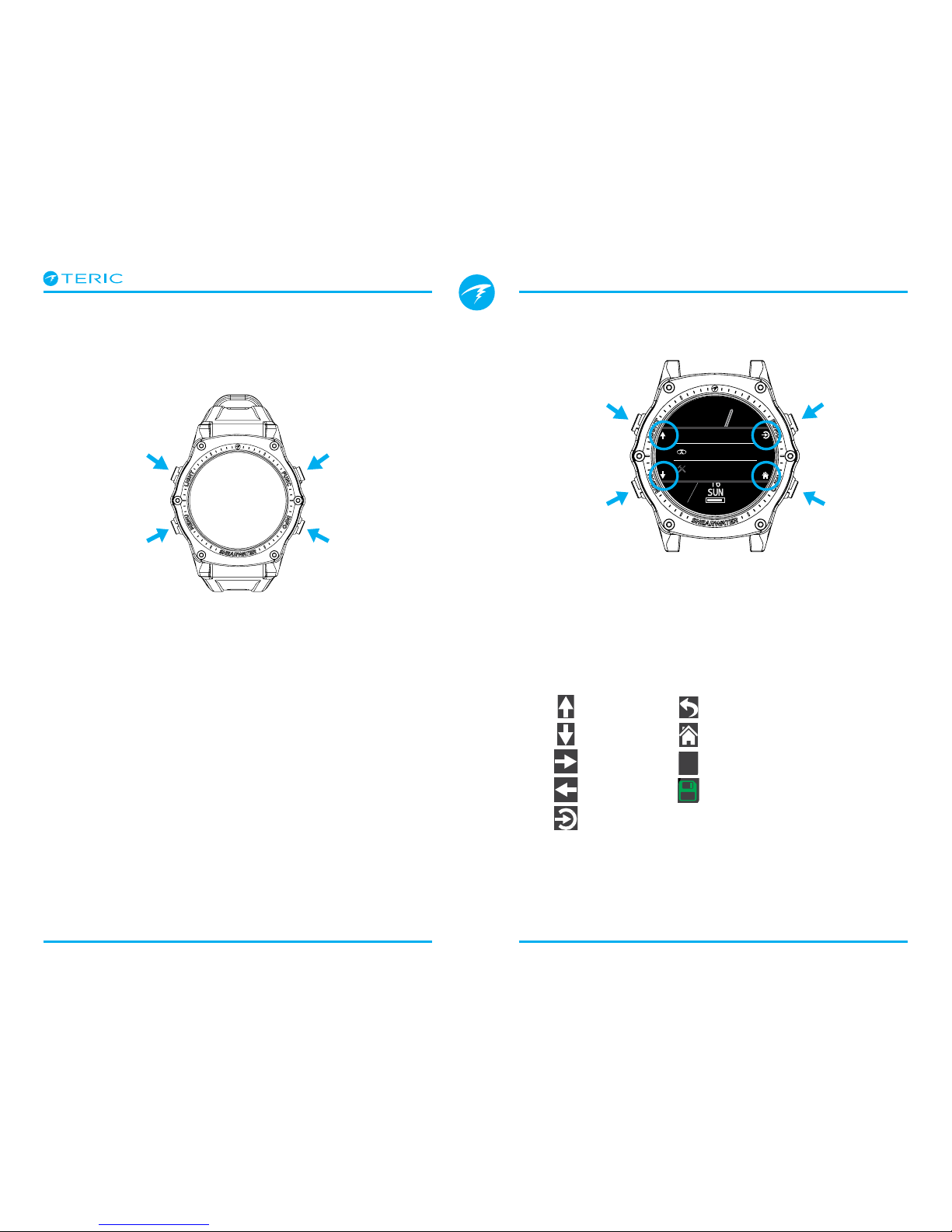
2.2. Buttons
All Teric operations are simple single button presses.
Don’t worry about remembering all the button rules
below. Button hints make using the Teric easy.
MENU Button (Lower Left)
From the main screen >Brings up the menu
In a menu >Moves down to the next menu item
INFO Button (Lower Right)
From the main screen >Cycles through info screens
In a menu >Exits back to the previous menu or main
screen
LIGHT button (Upper Left)
From the main screen >Cycles brightness levels
In a menu >Moves up to the next menu item
FUNCTION Button (Upper Right)
From the main screen >Configurable shortcut
In a menu >Selects menu item
FUNC
(Upper Right)
LIGHT
(Upper Left)
MENU
(Lower Left)
INFO
(Lower Right)
Button Hints
When in a menu, button hints label each button:
In the example above, the hints to the right tell us:
• Use LIGHT to move up a menu item
• Use MENU to move down a menu item
• Use FUNC to select a menu item
• Use INFO to go back to the home screen
Button Hint Icons:
Dive
Watch Tools
Gases ✘
Gases
UP
DOWN
NEXT
SELECT
HOME
CANCEL
SAV E
SELECT
UP
DOWN HOME
PREVIOUS
Deco
Deco Model
ZHL16C+GF
GF Conserv.
High 35/75
Last Stop
3 m
BACK

Operating Instructions
Page 9 RevA
2.3. Changing between Modes
The two primary modes are Watch mode and Dive
mode. Watch mode is only available at the surface.
Switching to Dive mode
To change from watch
mode to dive mode
manually, press the
Menu button and select
Dive from the main
menu.
Dive mode will
automatically be
triggered when a dive
starts.
Changing dive modes is covered on page 63.
Switching to Watch mode
To change from Dive
mode to Watch mode,
press the Menu button
and select Watch from
the main menu.
The Teric will revert
back to watch mode
after 15 minutes of
inactivity on the
surface.
Dive
Watch Tools
2.4. Owner Information Screen
Upon entering dive
mode, the owner
information screen
will be displayed for 15
seconds or until any
button is pressed.
Owner and contact
information can be
changed in the User
Info menu (page 75)
This display also confirms the current alert notification
settings and tests the alerts. Alerts notification
settings can be changed in the top-level Alerts menu.
2.5. Function Button
The function (upper
right) button is a
customizable shortcut
that makes accessing
your most used
functions on the Teric a
little easier.
The function button
can be customized
independently for every
mode of operation.
For Watch mode, the function button can be
customized in Settings > Watch.
For each dive mode, the function button can be
customized in Settings > Dive.
P
S
I
DECO
20 2 14
T1
1850
O2/He
21/00
ft min
TTS
.0
0
ft
mh
342
SURFACE
OC
21
%
mh
342
SURFACE
NDL TTS
----
FD
OC
Watch
Select Gas
Owner:SCUBA Steve
Contact:555-123-4567
Beep: OFF
Vib: ON

Operating Instructions
Page 10 RevA
3. Dive Mode Interface
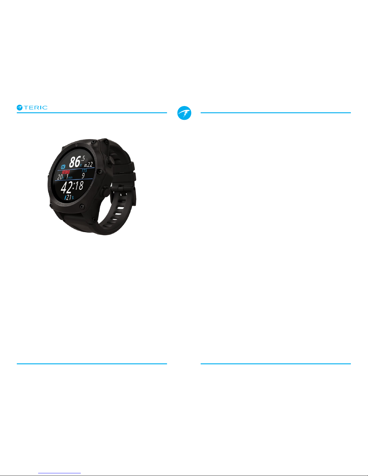
3.1. Default Dive Setup
The Teric comes per-configured for recreational
diving.
The default dive mode for the Teric is Open Circuit
Recreational (OC Rec) displayed with the “Big” screen
layout.
As a quick reference, a diagram of the default diving
display is shown below.
Many attributes of this default mode are shared with
the other dive modes. The following sections go into
detail about each screen element.
See the OC Rec Example Dive on page 28 for a
walk through of how this screen changes through all
phases of a dive.
42
:
18
.0
60
ft
21
%
NDL TTS
215
22
OC Rec
!
Battery Indicator
Depth
Dive Mode Ascent Rate
No Deco
Limit
Time To
Surface
Alert
Indicator
Dive Time
Active Gas
OC Rec mode with Big
screen layout
3.2. Dive Mode Differentiation
Each dive mode is designed to best suit a particular
type of diving.
OC Rec
Designed for use during recreational,
no-decompression diving activities.
• Nitrox Only - no helium
• Safety Stops
• Enhanced warnings
OC Tec
Designed for use during technical diving activities
including planned decompression.
• Full Trimix
• No Safety stops
• TTS permanently on screen in Big layout
CC/BO
Designed for use with a closed circuit rebreather.
• Fast switching from closed circuit to open circuit
(BO) operating modes.
• Separate customizable home screens for CC and
BO.
Gauge
Gauge Mode turns the Teric into a simple depth and
time display (a.k.a. a bottom timer). See page 34.
• No tissue tracking
• No decompression information
Freedive
Optimized for use while freediving. See page 35.
• Freediving sets.
Change the Dive Mode from the Dive Settings menu.
See details on page 63.

Operating Instructions
Page 11 RevA
Standard layout
The Standard screen layout has four rows and gives
the most information on the screen at the expense of
font size.
The Top, Bottom, and Deco row content are reserved
for the most critical information and are fixed, while
pressing the INFO button scrolls through additional
data in the Info row.
The Info row can be customized with up to three
pieces of information. Read mode about Home Screen
Customization on page 21.
The Standard screen layout is the default layout for
OC Tec and CC/BO.
3.3. Main Screen Layout
The Teric has two different screen layouts available in
every dive mode, Big and Standard.
Change the Screen layout from the Dive Settings Menu.
See details on page 63.
Big layout
42
:
18
.0
77
ft
21
%
NDL TTS
412
22
Top Row
Depth, Mode
& Ascent Rate
Info Row
NDL, TTS
& Deco Info
Bottom Row
Dive Time
ft
125.
P
S
I
6
23 19
:
DECO
20 2 14
T1
1850
O2/He
21/00
ft min
TTS
23
!
Top Row
Depth, Mode
& Ascent Rate
Deco Row
NDL, TTS
Info Row
Customizable
Bottom Row
Dive Time
The Big screen layout provides the largest font size at
the expense on screen information.
The top and bottom row contents are reserved for the
most critical information and are fixed, while pressing
the INFO button scrolls through additional data in the
Info row.
In some modes, the right Info row slot can be
customized. Read mode about Home Screen
Customization on page 21.
The Big screen layout is the default layout for OC Rec,
Freedive, and Gauge mode.
Operating Instructions
Page 12 RevA
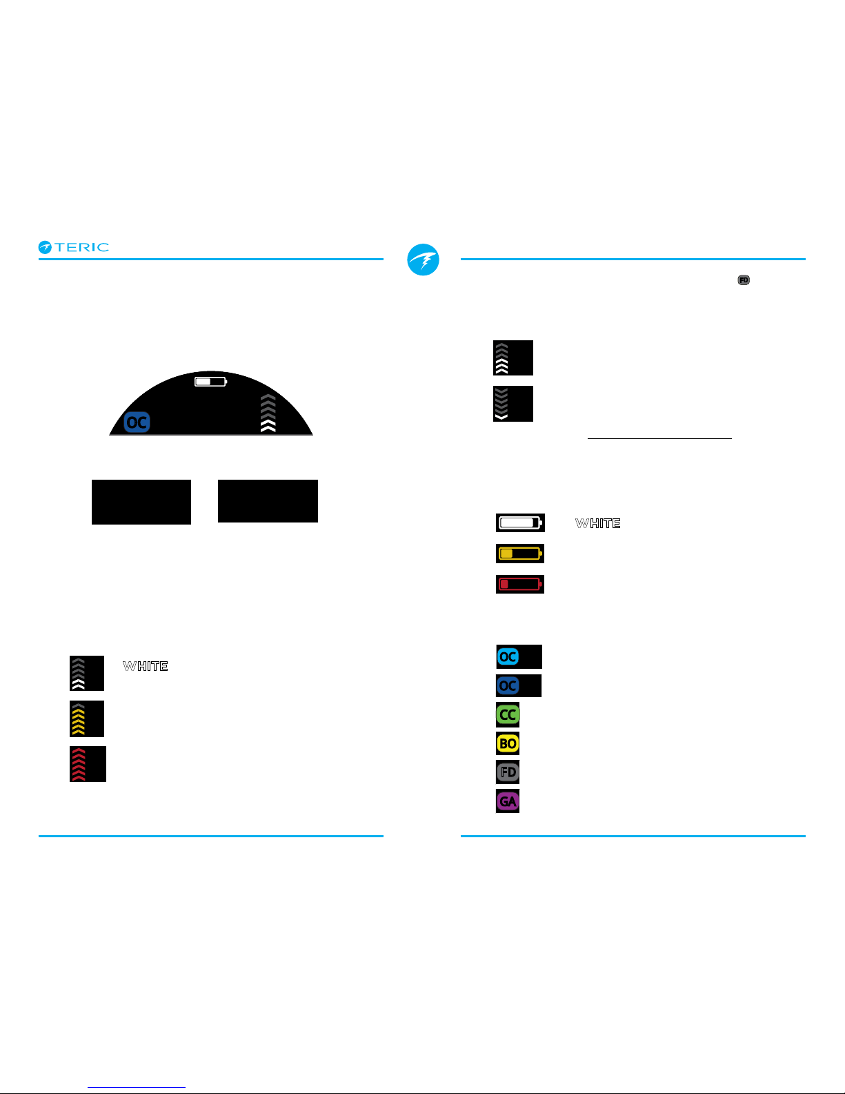
3.4. Detailed Descriptions
The Top Row
The top row shows depth, ascent rate, battery and
mode information.
Depth
Displayed to one decimal place in feet or meters.
Note: If the depth shows a Flashing Red zero or shows at
depth at the surface, then the depth sensor needs service.
Ascent Rate Display
Shows how fast you are currently ascending
graphically and numerically.
1 arrow per 10 feet per minute (fpm) or 3 meters per
minute (mpm) of ascent rate.
Note: Deco calculations assume 33fpm (10mpm)
ascent rate.
6
ft
125
.
7
m
32.
42
66
23
when less than 30 fpm / 9 mpm
(1 to 3 arrows)
YELLOW when greater than 30 fpm /
9 mpm and less than 50 fpm / 15 mpm
(4 or 5 arrows)
FLASHING RED when greater than
60 fpm / 15 mpm (6 arrows)
Freedive Mode Ascent / Decent Rate Display
Freedivers ascend much faster than SCUBA divers. So,
ascent rate in freedive mode is measured in feet per
second (fps) or meters per second (mps) rather than
feet per minute or meters per minute.
In freedive mode, 1 arrow per 1 fps / 0.3mps.
Descent rate is displayed in addition to ascent
rate in freedive mode.
Read more about Freedive Mode on page 35.
Battery Icon
The battery icon is shown on the surface but
disappears when diving. If low or critical then the
battery icon will appear while diving.
Dive Mode Indicator
The dive mode indicator is only shown at the surface
(except CC & BO mode).
when battery change is OK
YELLOW when battery needs to
be charged.
RED when battery must be
charged immediately.
OC
BO
OC
BO
CC
OC
BO
CC
FD
OC
BO
CC
FD
GA
OC Rec
OC Tec
Open Circuit Recreational (OC REC)
Open Circuit Technical (OC TEC)
Closed Circuit
Bailout (Available in CC/BO mode)
Freedive
Gauge Mode
ft
85
.6
TTS
23
OC Tec
NDL
OC
BO
CC
FD
2.6
1.3

Operating Instructions
Page 13 RevA
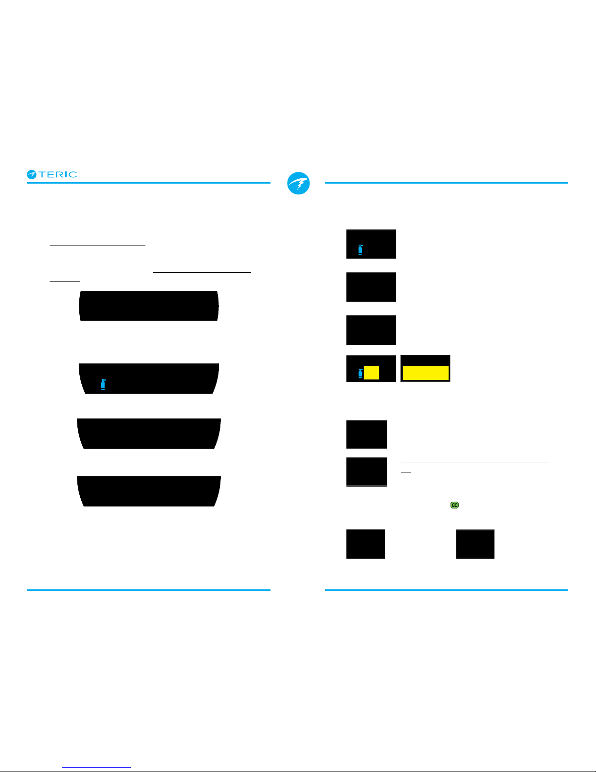
Deco Clear Counter
Safety Stop Counter
Time-To-Surface (TTS)
The Deco Row
The Deco Row is only shown in the Standard layout,
however, the Deco row information described below
is shown on the first page of the info row in the Big
layout.
No Decompression Limit (NDL)
Deco Stop Depth and Time
Once Mandatory decompression is required, NDL will
be replaced by decompression information.
By default the Teric uses a 10ft (3m) last stop depth.
At this setting, you may perform the last stop at 20ft
(6m) with no penalty. The only difference is that the
predicted time-to-surface will be shorter than the
actual TTS since off-gassing is occurring slower than
expected. There is also an option to set the last stop
to 20ft (6m) if you wish.
See the Decompression Stops section on page 25
for details.
20
NDL
5
NDL
The time remaining, in minutes, at the
current depth until decompression stops
will be necessary.
Displays in Yellow when the NDL is less
than 5 minutes.
125
DECO
20 2
O2/He
ft min
The shallowest depth to which you
can ascend and how long to hold
that stop.
42
0
CLEAR
1:14
In OC Tec and CC/BO mode, the deco
clear counter appears in the DECO box
and counts up from zero to show for
how long your decompression has been
clear.
42
0
SAFETY
3:22
In OC Rec mode, the safety stop
counter counts down automatically
when in the safety stop range. Displays
“Clear when the safety stop has
completed.
See the Safety Stops section on page
24 for details.
125
14
T1
min
TTS
23
The time-to-surface in minutes. This
is the current time to ascend to the
surface including the ascent plus all
required deco stops and safety stops.
125
O2/He
TTS
23
NDL
21 21
.0
0
ft
STOPWATCH
SURFACE
Deep
19:16
FD
CLEAR
SAFETY
Important!
All decompression information including
Deco Stops, NDL, and Time to surface are
predictions that assume:
• Ascent rate of 33fpm / 10mpm
• Decompression stops will be followed
• All programmed gases will be used as
appropriate
Read more about Decompression and
Gradient Factors on page 26.
Operating Instructions
Page 14 RevA
The default configuration of the Info row in the
Standard layout varies between different dive modes.
The Info Row
The Info row is the center row in the Big layout
and the third row in the Standard layout. Info row
information is customizable. See Home Screen
Customization on page 21 for details.
In the Big layout, the Info row shows decompression
information as described in The Deco Row section on
page 13.
O2
21
%
58
27 1
mmin
PPO2
.21
19 22
:
O2/He
18/45
58
27 1
mmin
PPO2
1.23
19 22
:
O2/He
10/50
58
27 1
mmin
19 22
:
1.3
SP
Default Info row CC/BO mode, Standard layout
Default Info row OC Rec mode, Standard layout
Default Info row OC Tec mode, Standard layout
Active Gas
In all three examples, the first Info row slot is taken by
the Active Gas.
In OC Rec mode, the percentage
oxygen in the breathing gas is
displayed.
In OC Tec mode, both the fraction of
oxygen and the fraction of helium are
displayed.
In CC/BO mode, the active gas refers to
the diluent gas.
Active gas displays in
yellow when a better gas
is available.
Partial Pressure of Oxygen (PPO2)
PPO2 of the current breathing gas.
Displays in Flashing Red when outside
customizable PPO2 limits.
Read more about PPO2 Limits on page
67.
\\
CC Internal Set point (SP)
The high and low internal set points are color coded.
O2
21
%
58
27 1
mmin
PPO2
.21
19 22
:
O2/He
18/45
58
27 1
mmin
PPO2
1.23
19 22
:
O2/He
10/50
58
27 1
mmin
19 22
:
1.3
SP
O2
21
%
58
27 1
mmin
PPO2
.21
19 22
:
O2/He
18/45
58
27 1
mmin
PPO2
1.23
19 22
:
MODCNS
%
11
mmin
PPO2
.21271
SURFACE
MODCNS
%
11
mmin
PPO2
1.71271
SURFACE
O2/He
10/50
58
27 1
mmin
19 22
:
1.3
SP
O2/He
10/50
58
27 1
mmin
19 22
:
0.7
SP
High Set point
is green
Low Set point
is magenta
OC
BO
CC
42
:
18
.0
60
ft
21
%
NDL TTS
215
22
OC Rec
!
Default Info row in OC Rec mode, Big layout
Operating Instructions
Page 15 RevA
The Bottom Row
Dive Time
The current length of the dive in minutes
and seconds
Surface Interval
When on the surface, the Dive Time is
replaced by a surface interval display.
Shows the minutes and seconds since the end of your
last dive.
Above one hour, the surface interval is displayed in
hours and minutes. Above 4 days, the surface interval
is displayed in days.
42 18
:
185021/00
42
:
18
ft
103.6 4:57
21
%
!
1753 20450
SURFACE
mh
3412
18/45
0.7
1753 20450
SURFACE
mh
3412
18/45
0.7
Bottom Row, OC Rec Mode
on a dive
Bottom Row, CC/BO Mode
at the surface
Alternate Active Gas and Set point Location
When the info row is not displaying the active
breathing gas (or diluent), or the current internal set
point, these values are displayed in the bottom row.
The alternate active gas location is at very bottom of
the computer display.
The alternate Set point location is at the far right of
the bottom row.
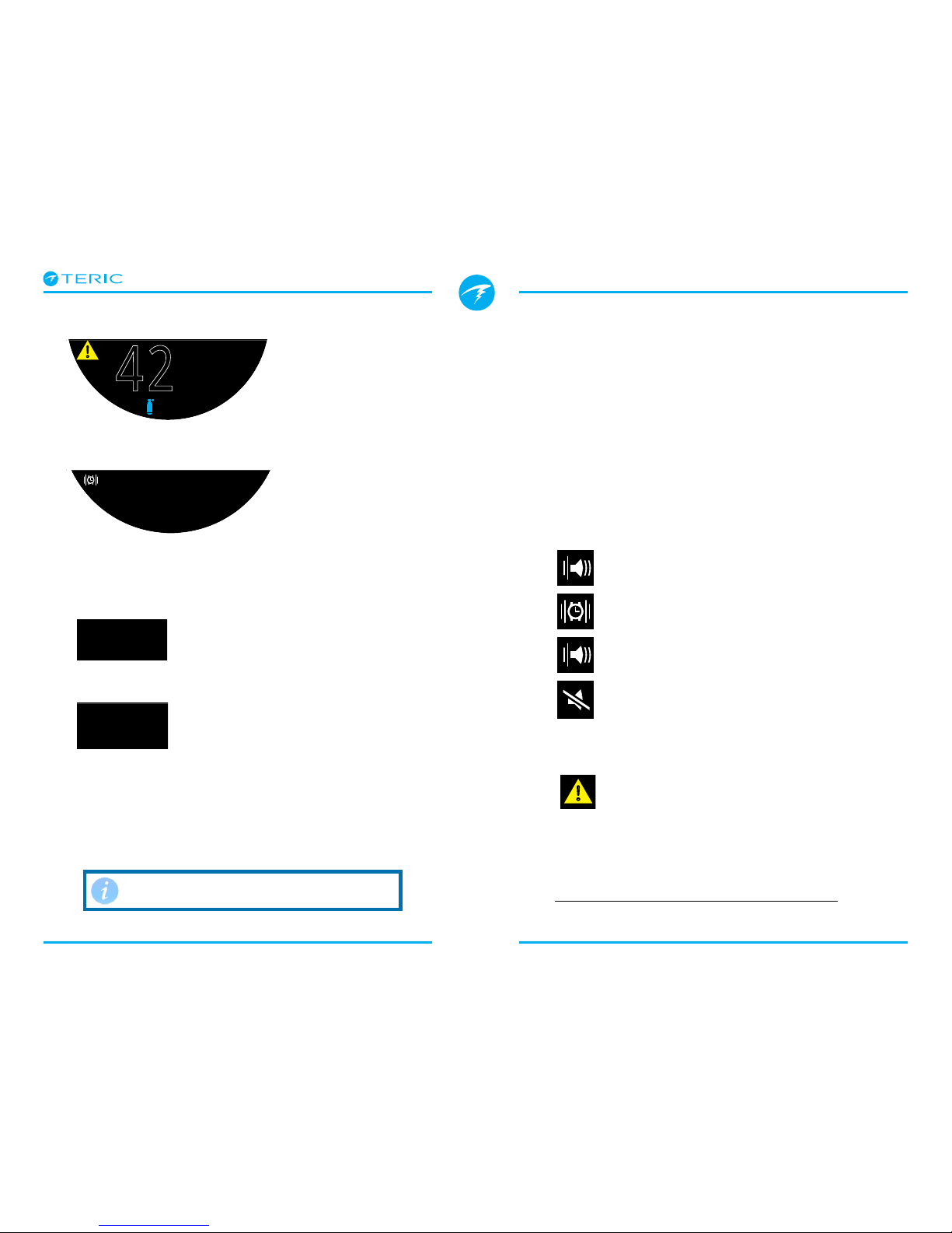
Notification Setting Icon
Indicates what notifications are turned on. Only
available at the surface.
Alert Indicator
Indicates there is a persistent warning
condition.
When the computer detects a dangerous situation,
such as high PPO2, a warning is triggered. The large
primary warning can be dismissed, but for some
critical situations this alert icon will persist until the
condition that caused the warning is resolved. See the
Alerts section on page 22 for more information.
Beep Only
Silenced
Beep and Vibrate
Vibrate Only
42
:
18
ft
103.6 4:57
21
%
!
The surface interval resets when
decompression tissues are cleared.
Operating Instructions
Page 16 RevA
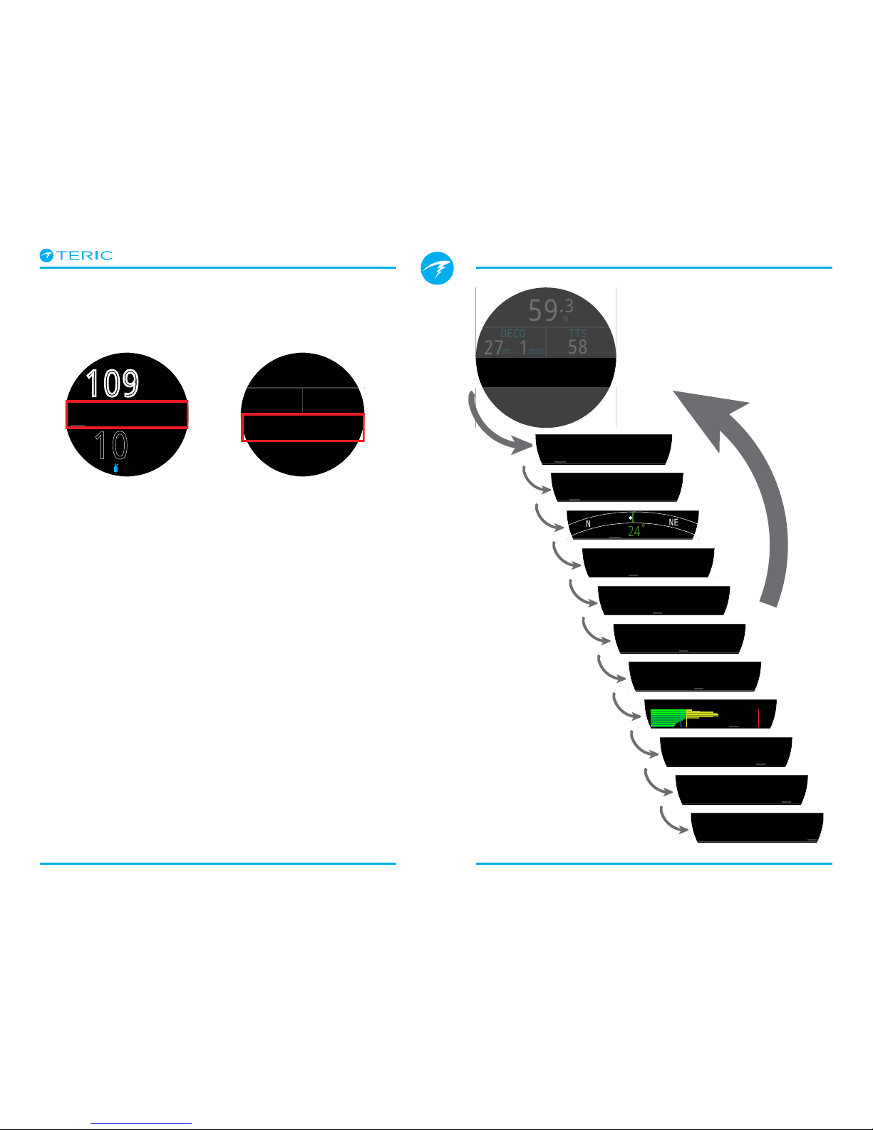
3.5. Info Screens
Info screens provide more information than is
available on the main screen.
From the main screen, the INFO (bottom right) button
steps through info screens.
When all info screens have been viewed, pressing
INFO again will return to the main screen.
Pressing the MENU (bottom left) button will also
return to the home screen at any time.
Info screens also automatically time-out after 10
seconds, returning to the home screen. This prevents
critical NDL, DECO and TTS information from being
hidden for an extended period.
When using the Standard layout the AI, compass and
Tissues Info screens do not automatically time out.
Note that although these screens are generally
representative of the Teric display, info screen content
varies for each mode. For example, decompression
related info screens are not available in gauge mode.
LAST DIVE
30.7 26:57
m
mmin
SURFACE
mmin
P
S
I
T1
1753
P
S
I
T2
1422
SURFACE
NE
N
24
mmin
SURFACE
MAX AVG
43.3
ft
103.6
ft
mmin
SURFACE
MODCNS
%
11
mmin
PPO2
.21271
SURFACE
mmin
GF
35/75
GF99
22
%
136
%
SurfGF
SURFACE
mmin
Δ+5
+8
@+5
20
CEIL
26
SURFACE
mmin
SURFACE
TISSUES
TEMP
21 49
BATTERY
%
�C
mmin
SURFACE
mBar SURF
1013
mBar NOW
2564
mmin
SURFACE
TIME
2:31
EOD
2:43
mmin
SURFACE
10
:
26
.9
109
ft
21
%
NDL TTS
10 4
m
59.3
O2/He
18/45
DECO
58
27
1
mmin
PPO2
1.23
19 22
:
TTS
m
59.3
O2/He
18/45
DECO
58
27
1
mmin
PPO2
1.23
19 22
:
TTS
Press the INFO button
(bottom right), to step
through Info Screens
Return to Main Screen by:
•Pressing MENU button
•Stepping past last screen
•Waiting 10 Seconds (most screens)
Big layout Info row
location
Standard layout Info
row location
Operating Instructions
Page 17 RevA
3.6. Info Screen Descriptions
Last Dive Info
Maximum depth and dive time from the last dive. Only
available at the surface.
Air Integration (AI)
Only available if AI feature is turned on. The contents
of the AI info line will automatically adapt to the
current setup.
Note that GTR and SAC are only available for a single
tank (selectable) and GTR is not available when in
deco.
More information about AI displays can be found in
section 9.
LAST DIVE
30.7 26:57
m
mmin
SURFACE
mmin
P
S
I
T1
1753
SURFACE
T1 Only
mmin
P
S
I
T1
1753 16
PSI
min
SAC T1 GTRT1
45
SURFACE
T1 & GTR/SAC
mmin
P
S
I
T1
1753
P
S
I
T2
1422
SURFACE
T1 & T2
mmin
T1
1753
T2
1422
GTR 45
SAC 16
SURFACE
T1, T2 &
GTR/SAC
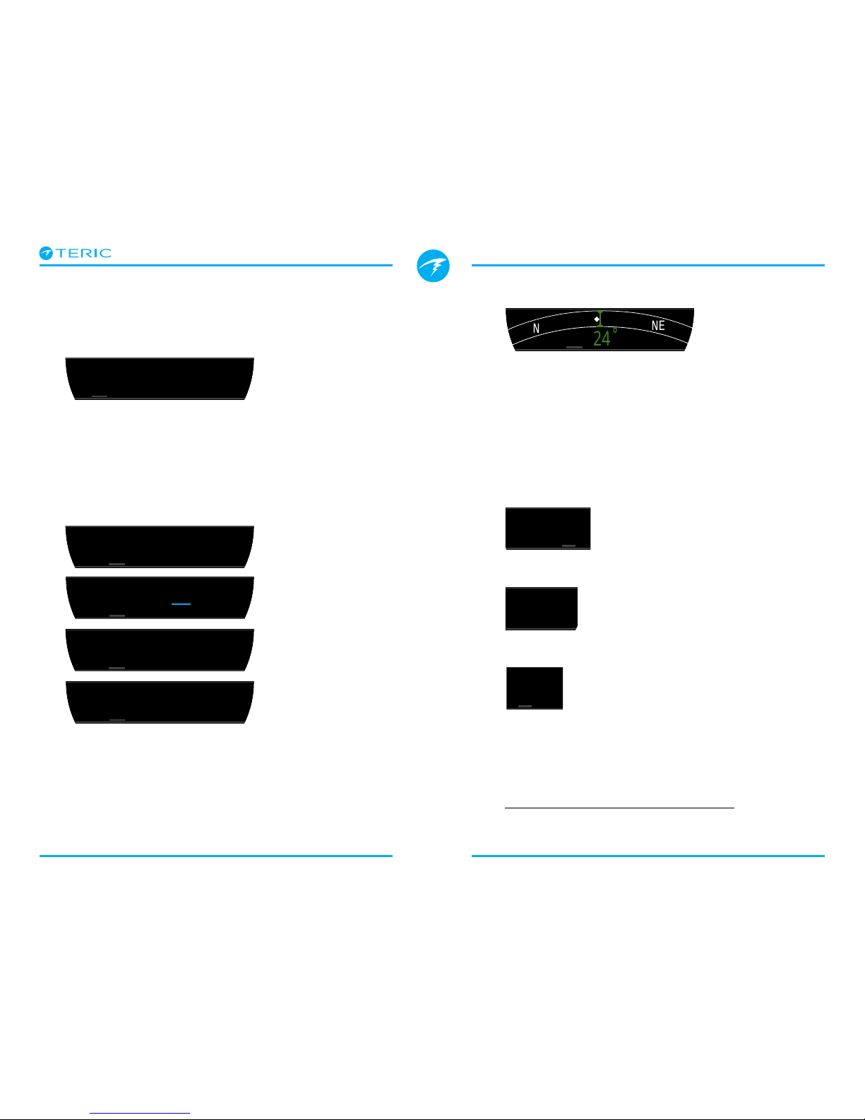
Compass
Marked headings appear in green while reciprocal
headings are shown in red. Green arrows point in the
direction of your mark when off course by 5˚or more.
Compass info row will not time out in Standard layout.
It is only available when compass feature is turned on.
See section 8.1 for more information on compass
calibration and use.
Maximum Depth
The maximum depth of the current
dive. When not diving, displays the
maximum depth of the last dive
Average Depth
Displays the average depth of the
current dive, updated once per
second. When not diving, displays
the average depth of the last dive.
Maximum Operating Depth
In OC mode MOD is the maximum
allowable depth of the current
breathing gas as determined by
PPO2 limits.
In CC mode, MOD is the maximum depth of the
diluent.
Displays in flashing red when exceeded.
Read more about PPO2 Limits on page 67.
NE
N
24
mmin
SURFACE
MAX AVG
43.3
ft
103.6 ft
mmin
SURFACE
MODCNS
%
11
mmin
PPO2
.21271
SURFACE
MAX AVG
43.3
ft
103.6
ft
mmin
SURFACE

Operating Instructions
Page 18 RevA
Partial Pressure of Oxygen in Diluent
DilPO2 displays the partial pressure
of oxygen in the diluent gas PPO2.
Displays in Flashing Red when
outside customizable PPO2 Limits.
When performing a manual diluent
flush, you can check this value to
see what the expected PPO2 will be
at the current depth.
CNS Toxicity Percentage
Central Nervous System oxygen
toxicity loading percentage. Turns
Yellow when greater 90%. Turns
Red when greater than 150%.
The CNS percentage is calculated
continuously, even when on the
surface and turned off. When deco
tissues are reset, the CNS will also
be reset.
The CNS value (short for Central Nervous System
Oxygen Toxicity) is a measure of how long you have
been exposed to elevated partial pressures of oxygen
(PPO2) as a percentage of a maximum allowable
exposure. As PPO2 goes up, the maximum allowable
exposure time goes down. The table we use is from
the NOAA Diving Manual (Fourth Edition). The
computer linearly interpolates between these points
and extrapolates beyond them when necessary.
Above a PPO2 of 1.65 ATA, the CNS rate increases at a
fixed rate of 1% every 4 seconds.
During a dive the CNS never decreases. When back
at the surface, a half-life of elimination of 90 minutes
is used. So for example, if at the end of the dive the
CNS was 80%, then 90 minutes later it will be 40%.
In 90 more minutes it will be 20%, etc. Typically after
about 6 half-life times (9 hours), everything is back
close to equilibrium (0%).
MODCNS
%
11
mmin
PPO2
.21271
SURFACE
MODCNS
%
101
mmin
PPO2
.21271
SURFACE
MODCNS
%
11
mmin
DilPO2
.21271
SURFACE
MODCNS
%
11
mmin
DilPO2
1.77271
SURFACE
Gradient Factor
The deco conservatism value when
the deco model is set to GF. The low
and high gradient factors control
the conservatism of the Bühlmann
GF algorithm. See “Clearing up the
Confusion About Deep Stops” by
Erik Baker for more information.
GF99
The current gradient factor as a
percentage (i.e. super-saturation
percent gradient)
0% means the leading tissue super-saturation is equal
to ambient pressure. Displays “On Gas” when tissue
tension is less than the inspired inert gas pressure.
100% means the leading tissue super-saturation is
equal to the original M-Value limit in the Bühlmann
ZHL-16C model.
SurfGF
The surfacing gradient
factor expected if the diver
instantaneously surfaced.
GF99 and SurfGF display in Red when the current
gradient factor modified M-Value is exceeded. Each
display in red when 100% is exceeded.
mmin
GF
35/75
GF99
22
%
136
%
SurfGF
SURFACE
mmin
GF
35/75
GF99
22
%
136
%
SurfGF
SURFACE
mmin
GF
35/75
GF99
22
%
136
%
SurfGF
SURFACE
OC
BO
CC
Operating Instructions
Page 19 RevA
Ceiling
The current decompression ceiling
not rounded to the next deeper
stop increment. (i.e. not a multiple
of 10ft or 3m)
@+5
“At plus 5” is the TTS if remaining
at the current depth for 5 more
minutes. This can be used as a
measure of how fast you are on-
gassing or off-gassing.
Δ+5
The predicted change in TTS if you
were to stay at the current depth
for 5 more minutes.
A positive “Delta plus 5” indicates that you are on-
gassing the leading tissue while a negative number
indicates that you are off-gassing the leading tissue.
Temperature
The current temperature in degrees
Celsius or degrees Fahrenheit.
Temperature units can be set in the
Display settings menu.
Battery
The Teric’s remaining battery level
expressed as a percentage.
Displays in yellow when battery is low and needs to
be recharged. Displays in red when battery is critically
low and must be recharged immediately.
mmin
Δ+5
+8
@+5
20
CEIL
26
SURFACE
mmin
Δ+5
+8
@+5
20
CEIL
26
SURFACE
mmin
Δ+5
+8
@+5
20
CEIL
26
SURFACE
TEMP
21 49
BATTERY
%
�C
mmin
SURFACE
TEMP
21 49
BATTERY
%
�C
mmin
SURFACE
Pressure
The pressure in millibars. Two values are shown,
the surface (surf) pressure and the current (now)
pressure.
Note that typical pressure at sea level is 1013 millibar,
although it may vary with the weather (barometric
pressure). For example, in a low pressure system
surface pressure may be as low as 980 millibar, or as
high as 1040 millibar in a high pressure system.
For this reason, the displayed PPO2 displayed on the
surface may not exactly match the FO2 (fraction of
O2), although the displayed PPO2 is still correct.
The surface pressure is set based on the lowest
pressure the Teric sees in the 10 minutes prior to the
start of a dive.
Time
In a 12 or 24 hour format. Time
format can be changed in the watch
settings menu.
End of Dive Time (EOD)
This is similar to TTS but is
expressed as a time of day.
The time of day at which you
can expect to surface if you
depart immediately, ascend at
10mpm or 33fpm, change gases
when prompted, and perform all
decompression stops as directed.
mBar SURF
1013
mBar NOW
2564
mmin
SURFACE
TIME
2:31
EOD
2:43
mmin
SURFACE
TIME
2:31
EOD
2:43
mmin
SURFACE

Operating Instructions
Page 20 RevA
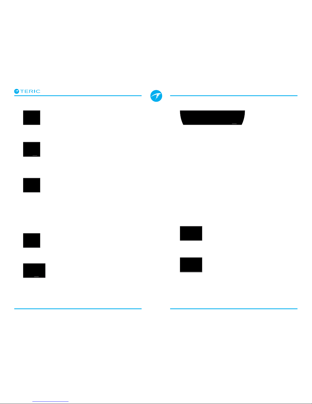
Sample Tissue Bar GraphsTissues Bar Graph
The tissues bar graph shows the tissue compartment
inert gas tissue tensions based on the Bühlmann ZHL-
16C model.
The fastest tissue compartment is shown on the
top, and the slowest on the bottom. Each bar is the
combined sum of the nitrogen and helium inert gas
tensions. Pressure increases to the right.
The vertical Cyan line shows the inert gas inspired
pressure. The yellow line is the ambient pressure. The
red line is the ZHL-16C M-Value pressure.
Tissues that are supersaturated above ambient
pressure are shown in yellow, and tissues that are
supersaturated above the M-Value are shown in red.
Note that the scale for each tissue compartment is
different. The reason the bars are scaled in this way is
so that the tissues tensions can be visualized in terms
of risk (i.e. how close they are as a percentage to
Bühlmann’s original super- saturation limits). Also, this
scale changes with depth, since the M-Value line also
changes with depth.
mmin
SURFACE
TISSUES
mmin
SURFACE
TISSUES
Inspired inert
gas pressure
Ambient
Pressure
Increasing
Pressure
M-Value
Pressure
16 tissue
compartments
{
mmin
SURFACE
TISSUES
On surface (sat. with air)
Note: Gas is 79% N2 (21% O2, or Air)
mmin
SURFACE
TISSUES
Immediately after descent
Deep Stop
mmin
SURFACE
TISSUES
On Gassing
mmin
SURFACE
TISSUES
Last deco Stop
Note: Gas is now 50% O2and 50% N2
mmin
SURFACE
TISSUES
Table of contents
Other Shearwater Watch manuals


