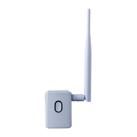
Sherlotronics RPT-800_V2 User manual

REPEATER UNIT
Model: RPT-800_V2
Instruction manual

SPECIFICATIONS:
Encryption.........................Code-Hopping
Frequency.........................433Mhz
Memory Capacity..............4000 Remotes
Receiving range................800m (open air)
Transmitting range............1500m (open air)
Power input range.............8 ~ 16V DC
Current drain.....................60mA, 12VDC
Dimensions.......................180 X 65 x 55mm
Weight (Packaged) ...........150 grams
Warranty............................2 year
DESCRIPTION OF FUNCTIONS:
The Repeater is used to strengthen signals thus extending the operation range of remote controls
which are required to work around large buildings indoors or outdoors. The Repeater unit will now
only Repeat signals that are LEARNT into its memory device. A maximum of 3992 Remotes may be
learnt in. The Repeater is compatible only to the Sherlotronics range of Code-hopping encryption
transmitters.
The New Version 2 Model, makes use of a memory device (Eeprom). This makes it possible to
learn in only the Remotes that are supplied with the system. The main benefit for this feature is to
limit the amount of RF traffic on the working frequency as the Repeaters will now only be able to
repeat signals that are physically learnt into the memory. We have added a Wire Terminal connector
block onto the PCB so that the installer can connect a long wire onto the unit and run it down to the
location which is easy to reach. When the unit is placed into LEARN mode the Repeater will firstly
Learn in the signal to its memory followed by repeat the signals out as a our previous models have
done. The repeater however may be left in LEARN mode for days if not Months at a time. If left in
LEARN mode the unit will work like the previous models and repeat any signal out that it receives as
we have termed “Promiscuous”. Once you taken the unit out of LEARN mode by un-bridging the
AUTO LEARN terminal connecter, the repeater will only respond and repeat signals that are actually
learnt into its memory. The unit has a memory capacity to 3992 Remotes.
The New Repeater also has a AC Fail Detect output as well as it can be set to transmit a System
Alive signal every 4 hours. Both the AC Fail and System Alive signals can be programmed into
either stand alone receivers or our Wireless Mimic base units.
As with the RPT-800_V1 Repeater, the masking feature is still implemented. This will prevent
unnecessary activity on the frequency from a particular remote that is used frequently. The Repeater
will mask the signal for 1 minute if it is received more than 5 times within a short period.
1.5km
Line of sight Built-up
500m
Indoors
120m
75m500m 120m
Line of sight Indoors
Built-up
APPLICATIONS:
- Shopping Centre Panic Systems
- Housing Estate Panic Systems
- Retirement Village Panic systems
- Farm Panic
Page 2

1
2
3
4
5
6
7
8
9
11
12
13
14
16
17
18
19
20 21 22 23
24
25
26
2728
29
30
32
33
34
35
36
37 38 39 40 41 42 43 44 46 47 48 49 50
51
52
53
54
55
56
5758
59
60
31
15
10
61
62
63
64 65 66 67 68 69 70 71 72 73 74 75
76
77
78
79
8081
82
8384
85
86
87 88 89 90
45
R
R
R
R
R
R
R
Repeater Unit
Typical Retirement Village Repeater Site Plan
Guard House 075
Page 3
OPENING & MOUNTING THE HOUSING:
The plastic housing is splash proof, and may be mounted externally if required. The receiver should be
mounted Vertically for best performance. Ensure that you do not mount the unit close to electric fences
cables or energizers, as these products
produce extreme levels of interference and may reduce the performance of the product. If mounting
indoors try and centralise the unit, and keep it at least 3 meters away from Armed Response company’s
alarm radio transmitters.
We recommend you mount the unit more than 2 metres above the floor height either inside a cupboard or
just above the trap door. For large properties that require reception range from the bottom of the drive
way, mount the unit in the garage which may be closer to the gate, and run a cable back to the Alarm
panel. Always conduct a signal range test before you hand over the product to the client, ensuring that
the remote works reliably from all areas of the site.
Insert a small 1-1.5mm flat screw driver into the slot
at the back of the housing and leaver the lid open.
Mount the Repeater unit as high as possible
building if you are requiring maximum range performance. This technique will improve the performance by
60% apposed to mounting the unit right up against a brick wall.
Run a good quality 6 core cable from the supplied 3.2A Power-supply to the Repeater unit. The reason you
need a 6 core cable is so that you can run two for the Power to the Repeater, one for the AC Fail detect and
then two for learning in the signals to the repeater. By running the LEARN wires to the inside of the power-
supply it will be easy to locate at a later stage, so it is important that the power-supply has easy access and
is not hidden away.
on either a Plastic or Aluminium pole on the exterior of a
SITE POSITIONING HINTS:
Using either a site plan or google maps, study the site
layout. Set repeaters on high points approx 75 meters
apart from each other.
This practice will ensure that the system has good signal
strength throughout all dwellings from behind walls.

WIRING DETAIL:
The Repeater should be wired to a 12V Power-supply. The LEARN input should be wired down to a easy
to locate position so that you will be able to easily place the Repeater into LEARN mode without having to
climb ladders or go into a roof.
Diagram: A
This wiring diagram shows how you should
wire up the Repeater V2 to the supplied
3.2A Power supply.
Do not exceed 100 meters if using
solid core comms cable.
100m MAX
cable run!
Page 4

Page 5
Diagram: B
MODEL:
3.2AMP
NEG
+12V
AC FAIL NEG
+12V
12VDC
10A/125VAC
28VDC
POS
NEG
Battery
Mark the wires
with the label supplied
in the packaging.
AUTO LEARN
This Diagram shows the actual connections done from the
power-supply to the Repeater pcb.
The AUTO LEARN wires are to be left loose inside the Power-
supply housing. Mark them with a label and insulate them for
peace of mind.
WIRING DETAIL:
The Repeater should be wired to a 12V Power-supply. The LEARN input should be wired down to a easy
to locate position so that you will be able to easily place the Repeater into LEARN mode without having to
climb ladders or go into a roof.
AUTO LEARN

To AUTO LEARN or program in the remote control
signals to the units memory, simply connect the
two AUTO LEARN terminals together.
Once a signal is learnt in the unit will flash the Rx LED
followed by the Tx LED.
Once all the remotes are programmed, you can disconnect the
wires connected to the AUTO LEARN terminals.
Please note: If the remotes are already handed out, and you
have no way of getting hold of them to program them in, it
will be quite acceptable to leave the unit in AUTO LEARN mode
for a few days or even a week if needed. The unit will work
the same whether it is in LEARN MODE or not.
LEDS explained:
Rx - one flash means it has received a programmed signal
Tx - one flash means that the unit is transmitting the signal
1. Remove all jumpers off the PCB.
2. Bridge the Default jumpers to the ON position for
10 seconds. The Rx & Tx LED will flash.
3. Once the unit is successfully defaulted all the LEDs
will turn on & stay on.
4. Remove the bridge from the ON position and wait for
the LEDs to turn off.
5. The unit is now ready to be reprogrammed.
LEARNING THE AC FAIL SIGNAL TO A STANDARD RECEIVER:
Then Bridge the AC Fail
jumpers on the Repeater
unit. The Receiver will
sound two beeps once it
has learnt in the signal.
Press the Learn switch on
the Receiver to take the
unit out of LEARN mode and
back into Normal operation
mode.
Step 3.
LEARN
2 beeps Long beep
Refer to the relevant Receiver programming procedure. Below is a standard
1 Channel Receivers programing procedure. Model RX1-500
PROGRAMMING THE REPEATER:
DEFAULTING MEMORY:
LEARN
Step 1. Step 2.
Press the Learn switch on
the Receiver unit
1 beep
Page 6

SYSTEM ALIVE / SUPERVISION FEATURE:
It is recommended that you enable this function if you are installing a Wireless Mimic base unit Model:
MB3000 Ver4, as the Mimic base unit will monitor the system alive signals from each repeater. If a
Repeater malfunctions or is removed from the system the Mimic base will report the problem within a 24
hour window time period. You will need to Learn in the System alive signal to the mimic base before it
will become active.
Please follow the procedure below to learn in the System alive signal to the MB3000 mimic base
unit.
24/07/2007 21:26:13
Memory
---- STORE REPEATER ----
Repeater 1
+1 +10 Store Ok
Press the far right button
to enter the Main Menu.
Press far left to move the
Arrow down to [5], then
press the far right
Ok button.
Press either +1 or +10 to
select the Repeater Location:
you want to Store a repeater.
Press Store followed by bridging the
Supervision jumpers to the ON
position. Wait until the “Active”
appears on the screen.
Press the far right Ok button to
return to the main menu.
Step2
Step3
Step4
Step1
Use the Up, Down and
Next button to enter the
PIN no: The default is
1;2;3;4. Pin no’s can
be changed in the Main
menu on option [7]
[5]Add/Del Repeater
[6]GSM Number
[7]Change PIN no
[8]Exit
24/07/2007 21:26:13
Memory
---- STORE REPEATER ----
Repeater 1
+1 +10 Store Ok
Step2
Step3
Step4
Step1
[5]Add/Del Repeater
[6]GSM Number
[7]Change PIN no
[8]Exit
Ok
Menu
— ENTER PASSWORD ---
1 2 3 4
Up Dn Next Ok
Page 7
Signal masking is a technique we have implemented which records the amount of signals received by a
particular remote control. If the same remote control is repeatedly transmitting the frequency will be highly
congested with RF noise and will cause interference on its self. We mask out signals that are received
more than 5 times in a 30 second period which are the same code. The mask period is 1 minute. Once the
minute has elapsed the Remote control will be repeated out if it is received by the repeater unit.
The reason we have implemented this feature is to ensure that transmitters that are connected to motion
detectors or beams do not cause continuos signal activation on a Panic system.
SIGNAL MASKING EXPLAINED:

This product is covered by this warranty for a period of one (1) year immediately subsequent to
the date of purchase indicated on the relevant invoice.
SHERLOTRONICS will replace or repair, at its option within a reasonable period of time, after it
receives the product, any part that proves to be defective in materials or workmanship. The
cost of parts and labour are included. All other costs are the responsibility of the purchaser.
Warranty Policy:
251 Aintree Ave, Northriding, Randburg, Johannesburg, South Africa.
Tel: +27 (0)11 462-5101 Fax: +27(0)11 462-8177 www.sherlotronics.com
Table of contents

