Sherwin-Williams System-ProCart 232584 User manual
824171
Rev. D
7930A
OWNER’S MANUAL
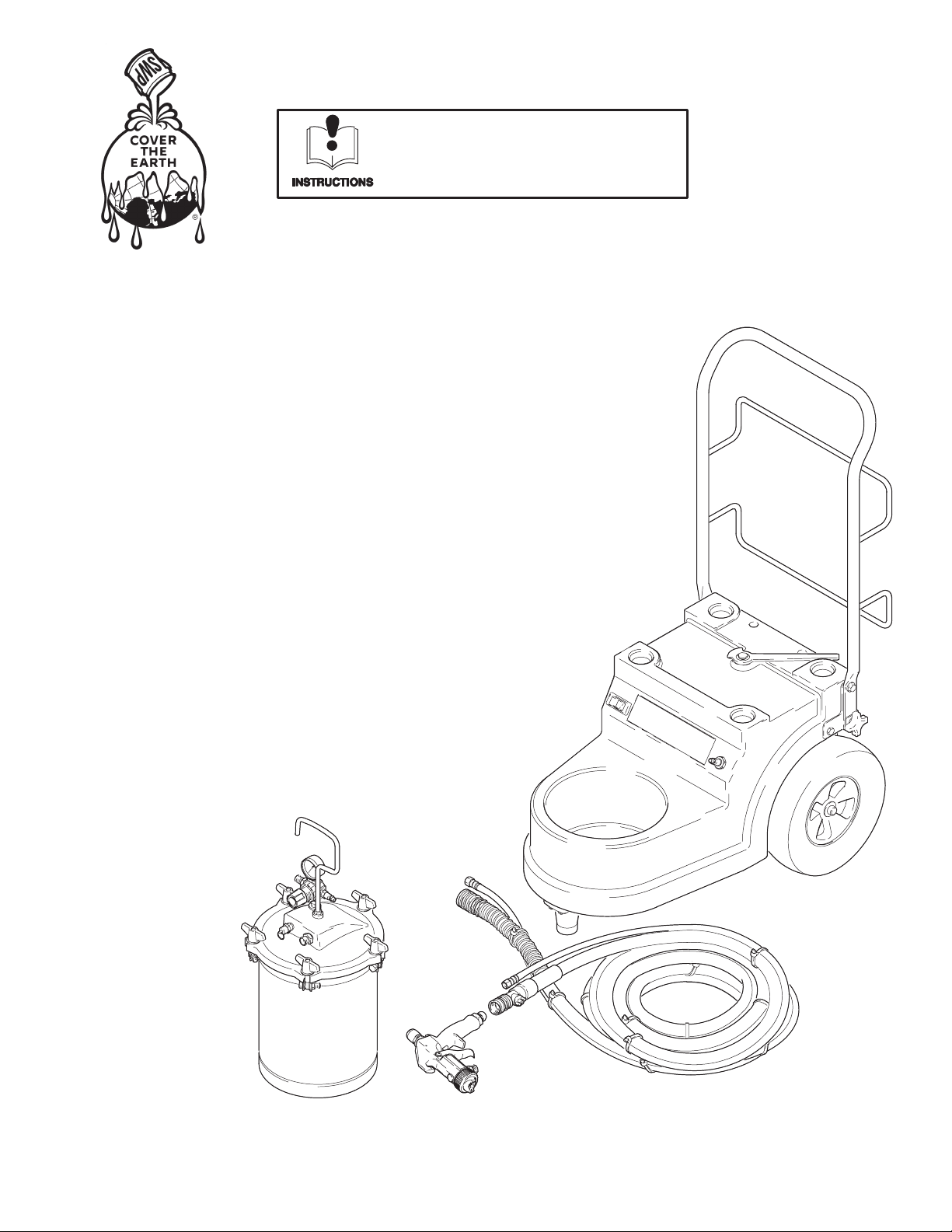
System-ProCartt
HVLP Compressor/Carts
120V AC, 50/60 Hz
15 psi (1.0 bar, 104 kPa) Maximum Working Pressure
Model 232584, Series A
Cart with 21/2-gallon remote pressure pot,
material hose, and compressor hose
Model 232585, Series A
Cart with 21/2-gallon remote pressure pot,
air and material hoses, and compressor hose
Model 232586, Series A
Cart with 21/2-gallon remote pressure pot,
air and material hoses, compressor hose, and
GTS-980 pressure-feed gun with #3 fluid set
Related Manuals
HVLP Turbine Sprayers 824170. . . . . . . . . . . . . .
GTS-960 Bleeder Gun 308336. . . . . . . . . . . . . . .
GTS-980 Non-Bleeder Gun 308810. . . . . . . . . . .
The SHERWIN–WILLIAMS COMPANY, CLEVELAND, OHIO 44115
ECOPYRIGHT 1998, GRACO INC.
This manual contains important
warnings and information.
READ AND RETAIN FOR REFERENCE
Table of Contents
Warnings 2. . . . . . . . . . . . . . . . . . . . . . . . . . . . . . . . . . . . .
General Information 4. . . . . . . . . . . . . . . . . . . . . . . . . . . .
Component Identification and Function 5. . . . . . . . . . . .
Setup 6. . . . . . . . . . . . . . . . . . . . . . . . . . . . . . . . . . . . . . . . .
Shutdown 11. . . . . . . . . . . . . . . . . . . . . . . . . . . . . . . . . . . .
Maintenance 12. . . . . . . . . . . . . . . . . . . . . . . . . . . . . . . . . .
Troubleshooting 13. . . . . . . . . . . . . . . . . . . . . . . . . . . . . . .
Repair 14. . . . . . . . . . . . . . . . . . . . . . . . . . . . . . . . . . . . . . .
Parts Drawing 16. . . . . . . . . . . . . . . . . . . . . . . . . . . . . . . . .
Parts List 17. . . . . . . . . . . . . . . . . . . . . . . . . . . . . . . . . . . . .
Specifications 17. . . . . . . . . . . . . . . . . . . . . . . . . . . . . . . . .
Sherwin–Williams Standard Warranty 18. . . . . . . . . . . .
Phone Number 18. . . . . . . . . . . . . . . . . . . . . . . . . . . . . . . .
Symbols
Warning Symbol
WARNING
This symbol alerts you to the possibility of serious
injury or death if you do not follow the instructions.
Caution Symbol
CAUTION
This symbol alerts you to the possibility of damage to
or destruction of equipment if you do not follow the
instructions.
WARNING
FIRE AND EXPLOSION HAZARD
Improper grounding, poor ventilation, open flames, or sparks can cause a hazardous condition and
result in a fire or explosion and serious injury.
DGround the equipment and the object being sprayed. See Grounding on page 6.
DIf there is any static sparking or you feel an electric shock while using this equipment, stop
spraying immediately. Do not use the equipment until you identify and correct the problem.
DProvide fresh air ventilation to avoid the buildup of flammable fumes from solvents or the fluid
being sprayed.
DWhen flammable liquid is sprayed or used for flushing or cleaning the equipment, place the
compressor at least 20 feet (6 m) away from areas where hazardous concentrations of flammable
vapors are likely to occur.
DUse additional air hose if necessary to ensure that the compressor is operated in a clean, dry,
well-ventilated area.
DNever place the compressor inside a spray booth! Use this equipment outdoors or in extremely
well-ventilated areas.
DKeep the spray area free of debris, including solvent, rags, and gasoline.
DElectrically disconnect all equipment in the spray area.
DExtinguish all open flames or pilot lights in the spray area.
DDo not smoke in the spray area.
DDo not turn on or off any light switch in the spray area while operating or if fumes are present.
DDo not operate a gasoline engine in the spray area.

WARNING
INSTRUCTIONS
EQUIPMENT MISUSE HAZARD
Equipment misuse can cause the equipment to rupture or malfunction and result in serious injury.
DThis equipment is for professional use only.
DRead all instruction manuals, tags, and labels before you operate this equipment.
DUse the equipment only for its intended purpose. If you are not sure, call your Graco distributor.
DDo not alter or modify this equipment. Use only genuine Graco parts.
DCheck equipment daily. Repair or replace worn or damaged parts immediately.
DDo not exceed the maximum working pressure of the lowest rated system component. The
Compressor/Cart has a working pressure of 15 psi (1.0 bar, 104 kPa).
DUse fluids and solvents that are compatible with the equipment wetted parts. See Specifications
on page 17 for this information.
DDo not use hoses to pull equipment.
DRoute hoses away from traffic areas, sharp edges, moving parts, and hot surfaces. Do not expose
Graco hoses to temperatures above 82_C (180_F) or below –40_C (–40_F).
DWear hearing protection when you operate this equipment.
DDo not lift pressurized equipment.
DComply with all applicable local, state, and national fire, electrical, and safety regulations.
DDo not point the gun at anyone or at any part of the body.
DDo not put your hand or fingers over the gun fluid nozzle.
DDo not stop or deflect leaks with your hand, body, glove or rag.
DDo not “blow back”fluid; this is not an air spray system.
DFollow the Pressure Relief Procedure on page 11 if the fluid nozzle clogs and before you clean,
check, or service this equipment.
DTighten all fluid connections before you operate this equipment.
DCheck the hoses, tubes, and couplings daily. Replace worn or damaged parts immediately.
TOXIC FLUID HAZARD
Hazardous fluid or toxic fumes can cause serious injury or death if splashed in the eyes or on the skin,
inhaled, or swallowed.
DKnow the specific hazards of the fluid you are using.
DStore hazardous fluid in an approved container. Dispose of hazardous fluid according to all local,
state, and national guidelines.
DAlways wear protective eyewear, gloves, clothing, and respirator as recommended by the fluid and
solvent manufacturer.
DDo not use 1,1,1-trichloroethane, methylene chloride, other halogenated hydrocarbon solvents or
fluids containing such solvents in the turbine spray system, which contains aluminum and/or
galvanized-coated parts. Such use could result in a serious chemical reaction, with the possibility
of explosion, which could cause death, serious injury, and/or substantial property damage.

General Information
Unpacking
Unpack the compressor/cart from the shipping carton,
and inspect for shipping damage. If anything is
damaged, call your distributor.
The contents of the System-ProCart HVLP
Compressor/Cart are as follows:
DCart with compressor
DMaterial hose
DAir hose (models 232585 and 232586 only)
DGTS 980 spray gun (model 232586 only)
DThis instruction manual
HVLP Compressor/Cart Information
The System-ProCart HVLP Compressor/Cart provides
air pressure to a 21/2-gallon remote pressure pot or to
a 2-quart remote pressure pot. Fluid under pressure is
propelled from the pressure pot to the turbine spray
gun.
HVLP System Operation
The System-ProCart HVLP Compressor/Cart, turbine
sprayer, and turbine spray gun comprises the HVLP
system. The HVLP system can spray most coatings or
finishes currently being used for automotive refinish,
industrial, aerospace, marine, wood, plastic, and
architectural applications.
The spray gun of the HVLP system utilizes inbound air
pressure from the compressor/cart and HVLP turbine
sprayer to produce a high-quality paint finish. The
spray gun produces a cone of air that carries and
directs paint from the gun to the surface with minimum
overspray. Application is easy because only a few
passes are required to obtain coverage. Increased
system transfer efficiency reduces material
requirements and clean-up time. The system complies
with clean air laws for reduced volatile organic
compounds (VOC) emissions.
See HVLP Turbine Sprayers manual 824170 for
information on the operation and use of the HVLP
turbine sprayer. See Turbine Gun manual 308336 or
308810 for information on the operation and use of the
turbine spray gun.
Various configurations of HVLP compressor/carts,
turbine sprayers, guns, and accessories are available
to meet specific application requirements.
System-ProCart HVLP Compressor/Cart Components Table
System-ProCart Material Hose Air Hose 980P Gun
232584 240476 none none
232585 240476 240059 none
232586 240476 240059 240103

Component Identification and Function
7930A
Fig. 1
E
C
B
G
D
A
F
H
I
J
ARemote pressure pot holder Provides space for 2-quart or 21/2-gallon remote pressure pots
BAir outlet Connection for compressor air supply to remote pressure pots
CTurbine latch Locks turbine sprayer in position on cart
DHose holder Provides storage space for sprayer hose, gun, and accessories
ECart handle Folds flat for minimum storage space
FTurbine sprayer base mount Provides lock-mount for turbine sprayer on cart
GON/OFF switch Power switch for compressor motor
HAir and material hoses Provide operating air and material to gun
IRemote pressure pot Holds 21/2gallons of application material
JTurbine spray gun Applies and controls flow of material to be sprayed
Setup
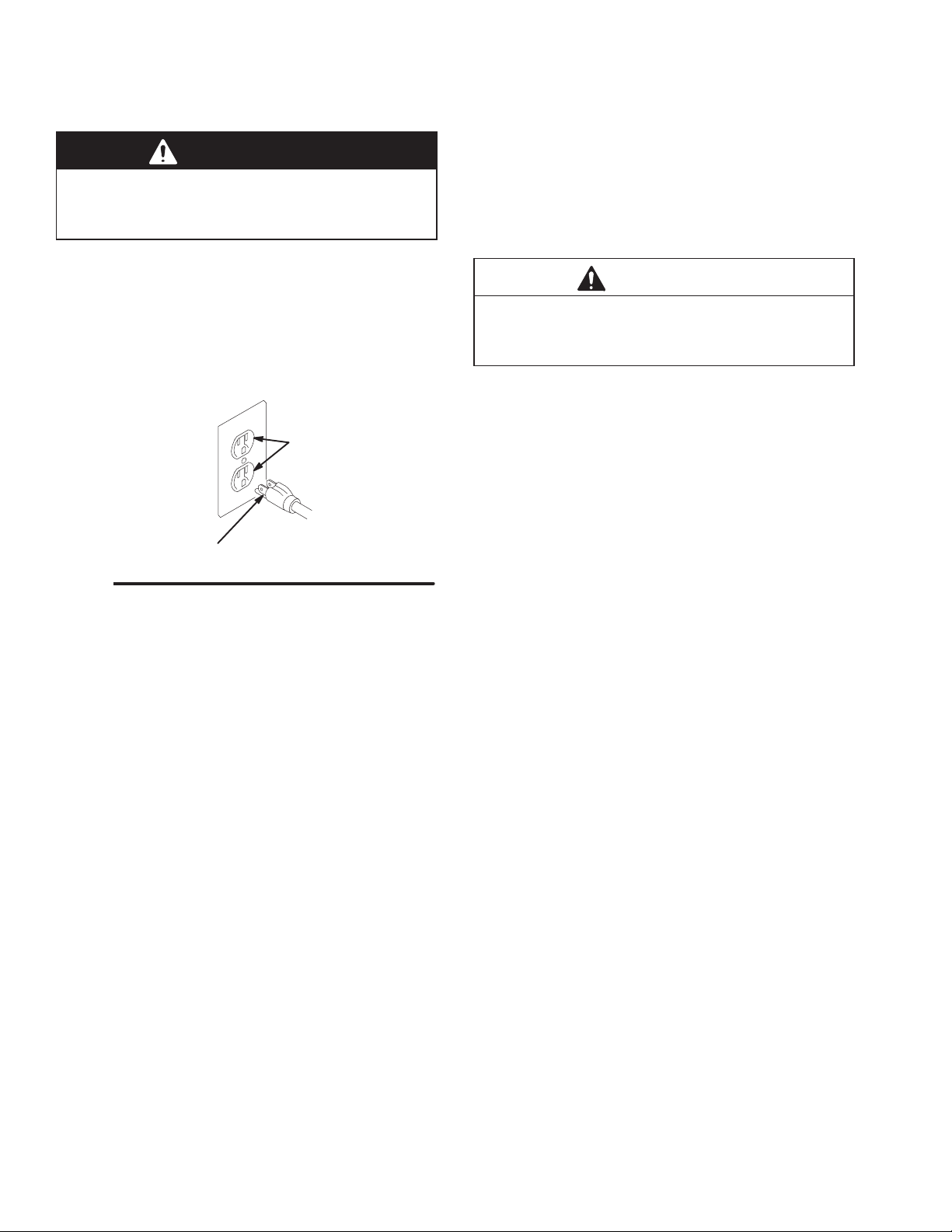
Grounding
WARNING
Improper installation or alteration of the grounding
plug will result in a risk of electric shock, fire or
explosion that could cause serious injury or death.
DThis equipment requires a 120V AC, 60 Hz, 15A
circuit with a grounding receptacle. See Fig. 2.
DDo not alter the ground prong or use an adapter.
DExtension cord must be 3-wire, 12 AWG, no longer
than 100 ft [30 m].
Fig. 2
grounding prong
grounded outlets
Setup/Use Options
The HVLP compressor/cart has a variety of user
options. See Fig. 3.
NOTES:
DSee Turbine Sprayer manual 824170 for
information on turbine setup and operation.
DSee Turbine Gun manual 308336 or 308810 for
information on turbine spray gun setup and
operation.
Prepare the Fluid
DAlways strain the fluid before you spray; this
includes color, reducer, and hardeners if used.
DUse a slower-drying reducer or thinner to
compensate for the faster drying time caused by
the warm air of the turbine. Do not over reduce.
CAUTION
The performance of the turbine sprayer varies with
the viscosity of the material and the length of the
hose. Keep the hose short to prevent pressure drop.
Paint Reduction —Automotive Type Finishes
Reduce and catalyze all paint to manufacturer’s
specifications. To compensate for the faster drying
time of turbine systems, use a reducer that is one step
slower than what is used for conventional air spray.
Paint Reduction —Industrial or Domestic
Coatings
Reduce and catalyze all paint to manufacturer’s
specifications. If no reductions are given, first
thoroughly mix the fluid to be sprayed, then gradually
mix in the proper reducer. Test the fluid until you have
the correct spraying consistency.
To test the consistency, remove the stir stick from the
thinned paint. When the paint stream running off the
stir stick breaks into droplets, the first few drops should
be about one second apart.

7932A
7931A
Storage Position for Cart Handle
1. Turn knob to free handle.
2. Fold handle down to store.
Remote Pressure Pot
1. Place remote pressure pot in pressure pot
holder on cart.
2. Follow Connect Fluid and
Air Supply instructions
on page 8.
remote
pressure
pot
turbine sprayer
(see manual 824170)
Compressor/cart with 21/2-gallon
remote pressure pot
Turbine Sprayer
1. Place turbine sprayer on cart.
2. Move latch on cart to the right to lock turbine sprayer.
3. Plug compressor/cart power cord into auxiliary
electrical outlet on turbine sprayer or into a separate
grounded electrical outlet.
4. Plug turbine sprayer into grounded electrical outlet.
NOTE: Extension cord must be 3-wire, 12 AWG, no
longer than 100 ft [30 m].
turbine sprayer
latch
auxiliary electrical outlet
knob
Fig. 3
7933A
Setup
7934A
Fig. 4
C
D
D
F
J
J
A
G
G
G
C
A
B
L
E
E
ZZ
HH
F
KK
Y
XX
Y
Y
Z
X
cup-over option
See manual
308336 or 308810
21/2-gallon remote pressure pot
cup setup for spray gun
remote pressure pot setup for
spray gun
2-quart remote pressure pot
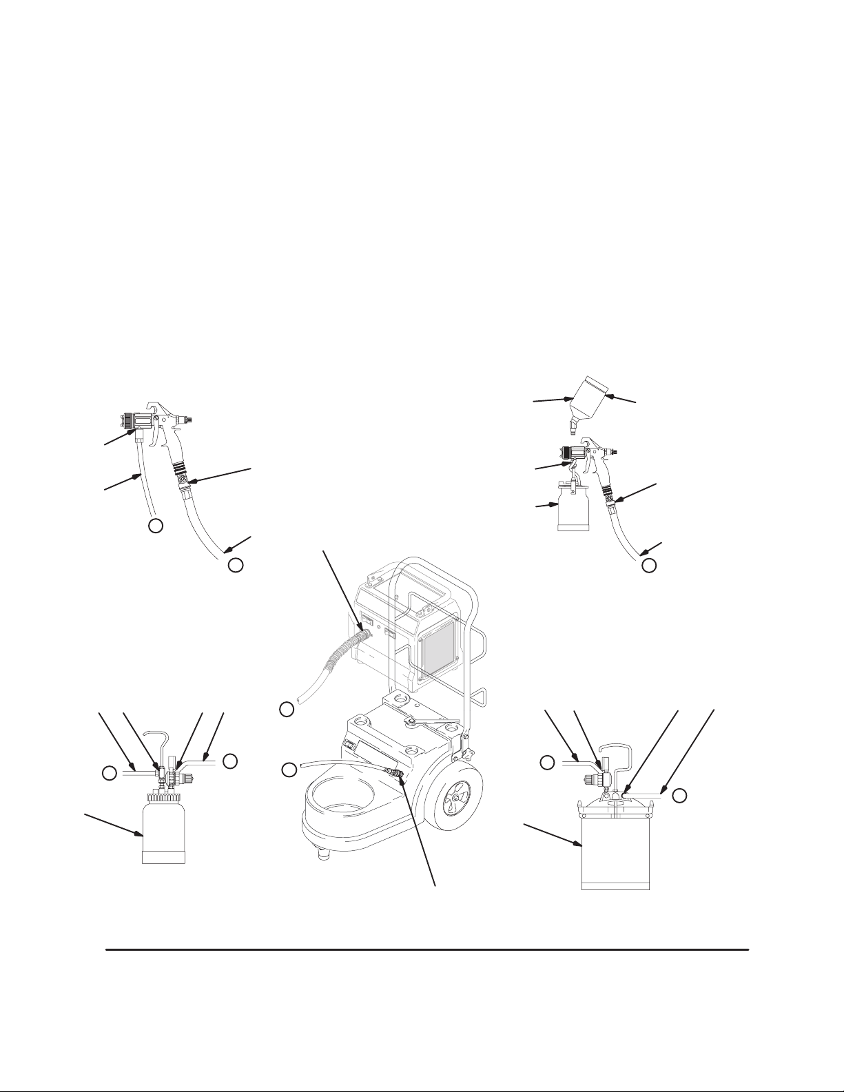
Setup
Connect Fluid and Air Supply
See Fig. 4.
DThe HVLP Compressor/cart provides the air supply
for remote pressure pots.
DThe circled letters in Fig. 4 indicate hose line
connections.
1. Connect gun air supply hose (A) between turbine
air outlet (B) and gun air inlet (C). DO NOT use
wrench to tighten connections; hand tighten only.
The System-4900 turbine uses a quick connector
at the air outlet (B). A wrench is not required for
hose connection.
2. If using spray gun cup (D):
Connect cup to gun fluid inlet (E).
If using accessory remote pressure pot (F):
Connect fluid supply hose (G) between remote
pressure pot fluid outlet (H) and gun fluid inlet (E).
Connect pressure pot air hose (J) between
pressure pot air regulator inlet (K) and cart
compressor air outlet (L).
Connect to Electric Supply
See Turbine Sprayer in Fig. 3 on page 7.
Setup
Fill the Cup or Remote Pressure Pot
Spray Gun Cup
WARNING
The spray gun cup is pressurized by the gun’s air
supply. To reduce the risk of serious injury from
pressurized fluid or accidental spray from the gun,
always turn off the air supply to the gun before you
remove the spray gun cup.
Only fill the cup 3/4 full to help keep the air pressure
tube clean, then install the cover. The under-cup cover
has a latch (H) to secure it to the cup. The over-cup
has a notched ring (J) that secures the cup hood into
place on the cup.
Fig. 5
02845
H
J
02845
Accessory Remote Pressure Pot
WARNING
The accessory remote pressure pots remain pres-
surized until pressure is manually relieved. To
reduce the risk of serious injury from pressurized
fluid or accidental spray from the gun, always
relieve pressure in the pressure pot before you
loosen or remove the cover.
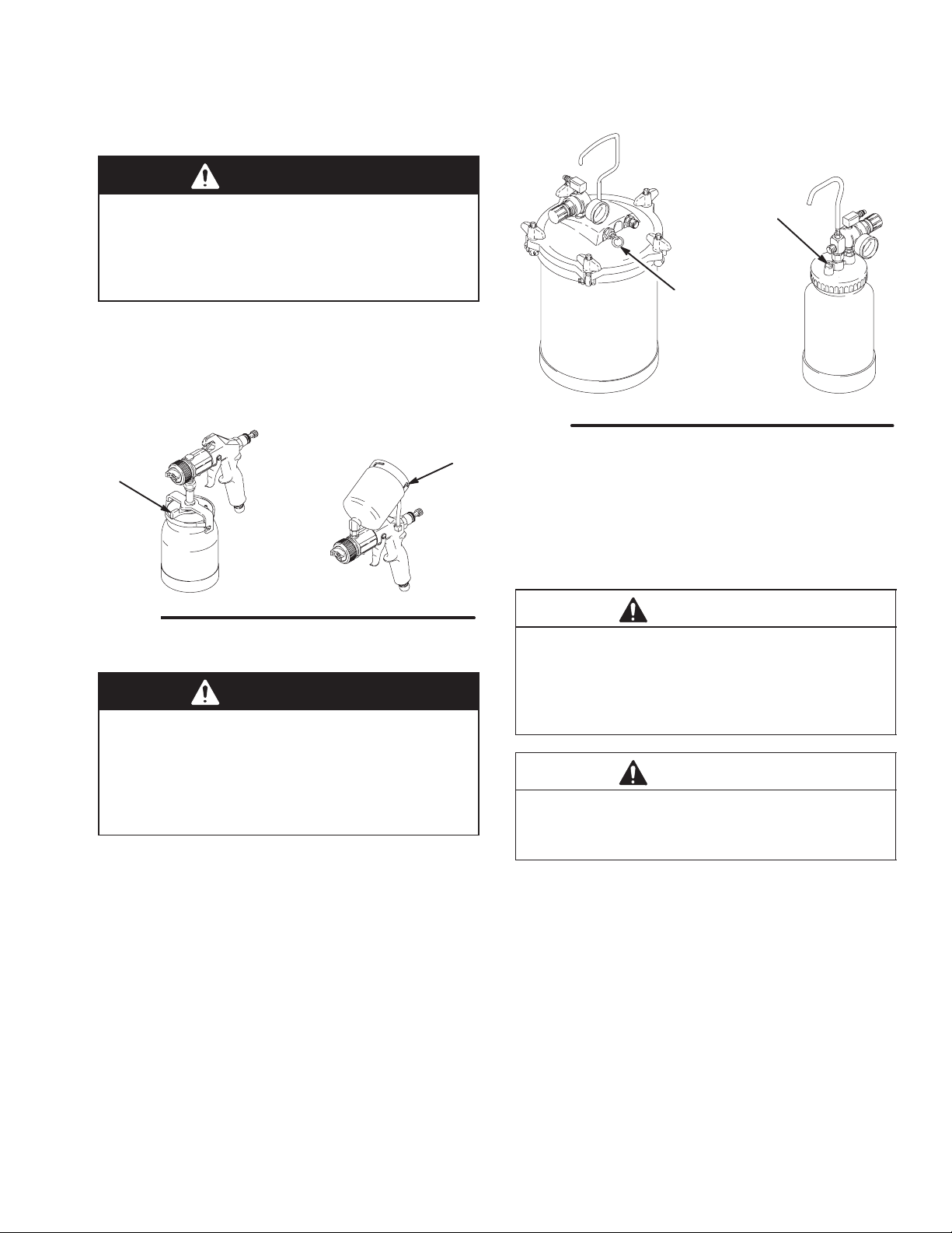
1. Relieve remote pressure pot pressure as follows
(see Fig. 6):
a. Turn off air supply to pressure pot.
b. 21/2-gallon remote pressure pot:
Pull pressure relief valve ring (206c) until
pressure is completely relieved.
2-quart remote pressure pot:
Turn out pressure relief knob (113) one turn.
Wait until pressure is completely relieved
before you remove cover. Close knob.
Fig. 6
206c
02882
113
02860
2 quart
21/2gallon
2. Remove pressure pot cover, fill pressure pot, and
secure cover.
3. 2-quart remote pressure pot only:
Lightly coat the cover threads with petroleum jelly.
CAUTION
If the 2-quart remote pressure pot is accidentally
tipped over or held at too great of an angle, fluid
could leak into the air regulator and cause damage.
Take precautions to avoid this. If fluid gets into the
regulator, clean it immediately.
CAUTION
Do not tighten the pressure pot cover more than
hand-tight. Excessive tightening can damage the
cover gasket.

Setup
Prepare the Surface to be Sprayed
To achieve proper adhesion, make sure the surface to
be sprayed is completely clean.
Operating the Compressor
WARNING
Sparking can be expected in the normal operation
of the motor. Sparks could ignite fumes from
flammable liquid, dust particles, and other
flammable substances in the spray area and cause
serious injury and property damage.
Follow the precautions below:
DWhen flammable liquid is sprayed or used for
flushing or cleaning equipment, place the
compressor at least 20 feet (6.1 m) away from
areas where hazardous concentrations of
flammable vapors are likely to occur.
DUse additional air hose if necessary to ensure
that the compressor is operated in a clean, dry,
well-ventilated area.
DNever place the compressor inside a spray
booth! Use this equipment outdoors or in
extremely well-ventilated areas.
DAvoid all ignition sources such as static
electricity from plastic drop cloths, open flames
such as pilot lights, hot objects such as
cigarettes, and arcs from connecting or
disconnecting power cords or turning light
switches on and off. Extinguish or remove all
sources of ignition.
1. Turn the compressor on a few minutes before you
start spraying to allow for warm-up time.
NOTE: When the compressor is not in use for an
extended period of time, turn it off. The compressor
does not shut off automatically.
2. Be sure the compressor filter is clean before
operating. See page 12 to check and clean the
filter.
NOTE: To adjust the spray gun pattern, see Turbine
Gun manual 308336.
Cold Weather Operation
The HVLP compressor/cart uses a diaphragm
compressor. A new diaphragm might be stiff in cold
weather. If cold enough, the diaphragm is too stiff to
allow the compressor motor to start (the unit hums).
If this occurs, follow these steps:
1. Turn turbine and compressor OFF.
2. Unplug turbine from power source.
3. Remove filter. Clean or replace if dirty.
4. Spin cooling fan on compressor for a few
revolutions.
5. Reassemble filter.
6. Plug in turbine.
7. Turn turbine and compressor ON. If necessary,
repeat procedure.

Shutdown
Pressure Relief Procedure
WARNING
PRESSURIZED EQUIPMENT HAZARD
The equipment stays pressurized until pressure is
manually relieved. To reduce the risk of a serious
injury from pressurized fluid, accidental spray from
the gun, or splashing fluid, follow the Pressure
Relief Procedure whenever you
DAre instructed to relieve the pressure
DStop spraying
DCheck or service any of the system equipment
DInstall or clean the fluid nozzles
1. Turn off air supply to gun.
2. Turn off turbine sprayer.
WARNING
The turbine hose outlet can get hot. Carefully check
the hose end before you remove the hose.
3. If using remote pressure pot:
Relieve pressure by following these steps (see
Fig. 7):
a. Turn off air supply to pressure pot.
b. 21/2-gallon remote pressure pot:
Pull pressure relief valve ring (206c) until
pressure is completely relieved.
2-quart remote pressure pot:
Turn out pressure relief knob (113) one turn.
Wait until pressure is completely relieved
before you remove cover. Close knob.
Fig. 7
206c
02882
113
02860
2 quart
21/2gallon
NOTE: Elevate spray gun and pull trigger. This will
allow fluid in fluid hose to drain back into remote
pressure pot.
4. If using a spray gun cup:
Unlatch cup cover, and loosen or remove cup from
cover to relieve cup pressure.
5. Clean spray gun and cup as instructed in Turbine
Gun manual 308336 or 308810.
Maintenance
Daily
Check the cart daily for cleanliness.
The compressor system is lifetime lubricated. The only
maintenance required is filter cleaning and
replacement.
The compressor filter must be clean at all times to
provide sufficient air flow to cool the motor and
sufficient pressurized air to the remote pressure pots.
Check the filter daily. Clean or replace as necessary.
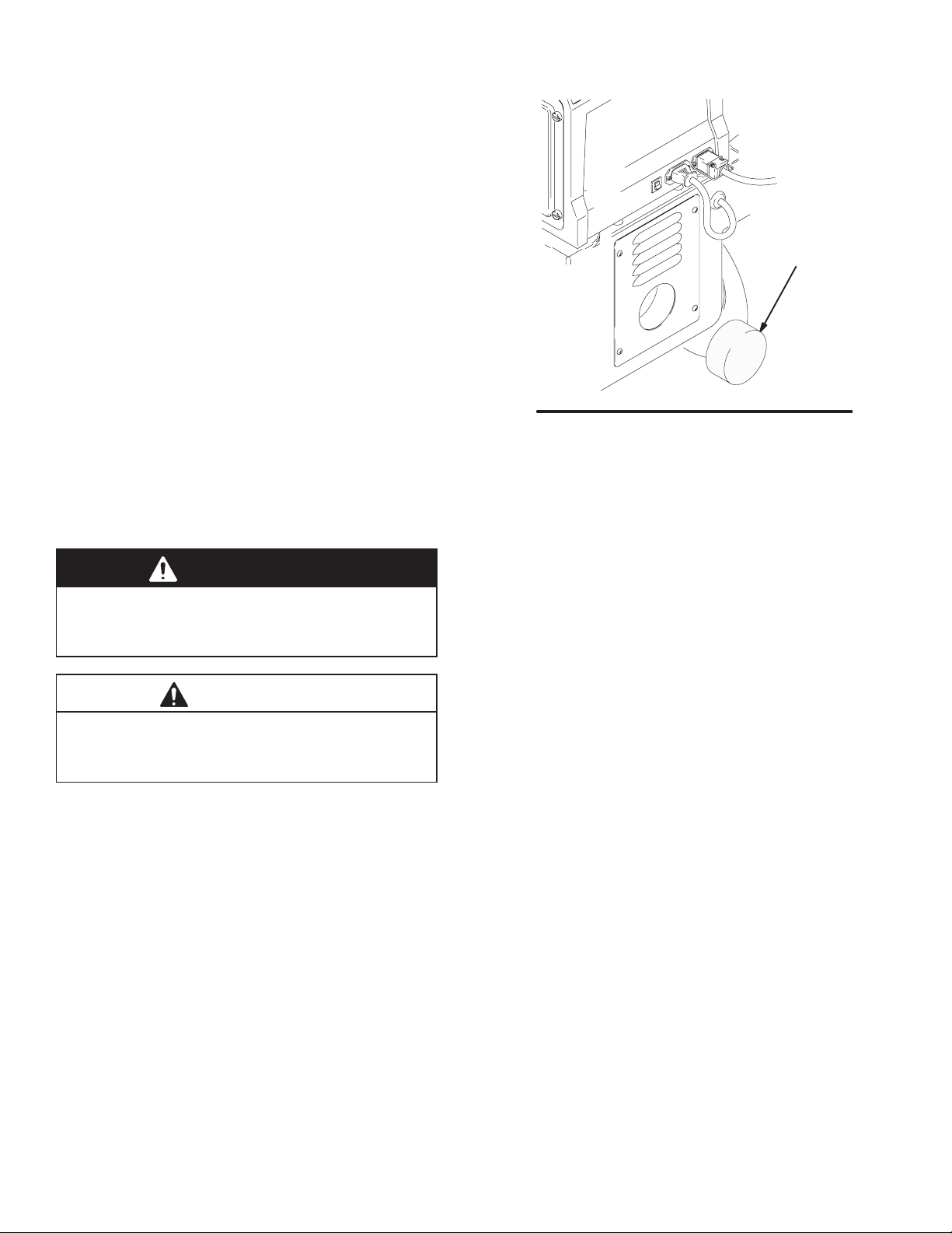
To service the compressor filter
1. Turn off and unplug compressor.
2. Pinch filter (A) and remove by hand. See Fig. 8.
3. Clean or replace filter as follows:
a. Brush accumulated paint and dirt from surface
of foam filter.
b. Rinse filter in water with mild detergent. Blow
dry.
c. Replace filter if paint is caked on.
WARNING
To avoid damage to the compressor and possible
electric shock, never install a damp filter in the
compressor.
CAUTION
Dust and dirt can accumulate during use and cause
equipment damage. Do not operate the compressor
without the filter installed.
Fig. 8
A
7935A
Weekly
Check hoses for cracks, leaks, and holes. Replace, as
necessary.

Troubleshooting
PROBLEM CAUSE SOLUTION
No fluid delivery No material, no remote container
pressurization, hose or pickup tube
clogged
Check container for material.
Check for leaks at the container gasket
(2-quart pressure pot cover or
21/2-gallon pressure pot wing nuts).
Tighten wing nuts if loose.
Check for air flow from male quick
disconnect at compressor outlet
(approx. 1/4 CFM).
Turn pressure regulator clockwise.
Look for pressure on gauge. (If no
pressure on gauge, check air line and
fittings).
Check hole in 21/2-gallon pot cover
under regulator or in 2-quart pot cover
at needle valve.
Clean if necessary.
Check for obstructions or kinks in
hoses and fittings.
Check if fluid pickup tube is unplugged.
Tighten.
Blow out and clear material hose.
Compressor not starting Cold weather operation See Cold Weather Operation on
page 10.
Repair
WARNING
Turn off turbine and unplug power for the following procedures.
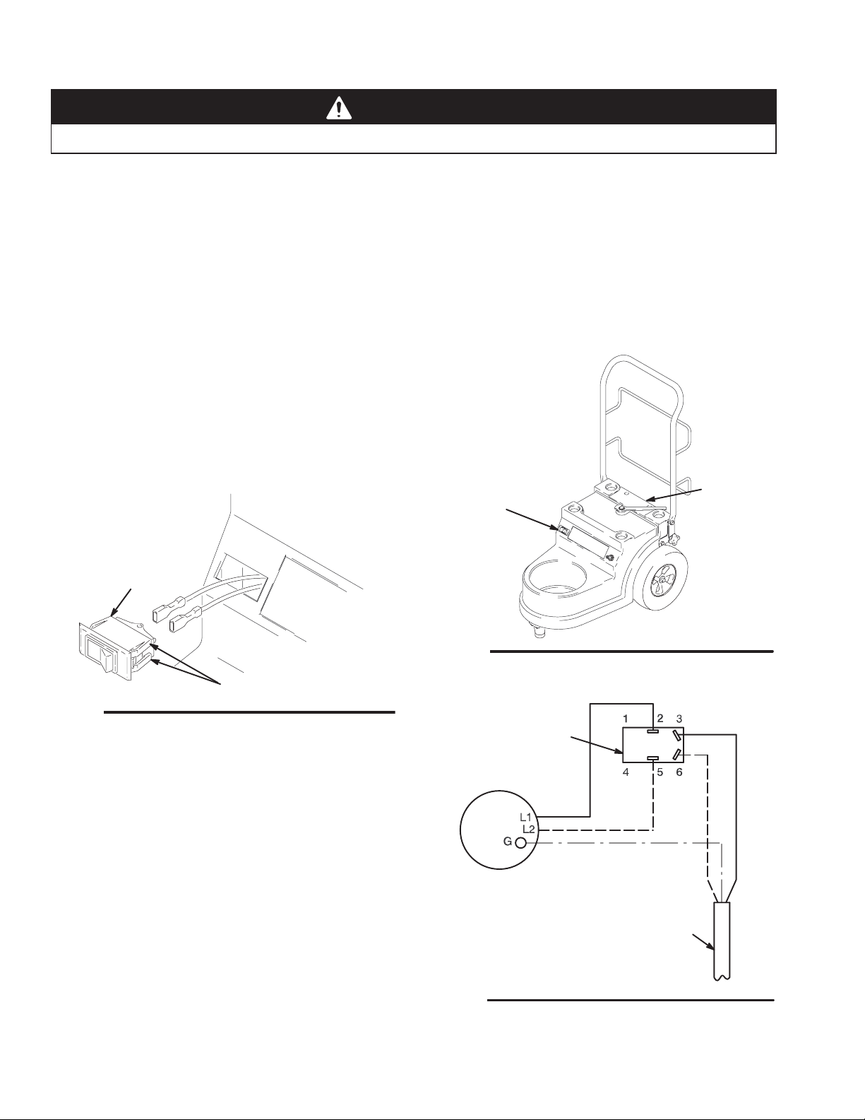
Compressor/Cart Switch Replacement
See Fig. 9, Fig. 10, and Parts Drawing on page 16.
1. To remove compressor power switch (28), wedge
large flat-blade screwdriver between top of switch
and cart face plate.
2. Push down firmly on switch. Pry switch out far
enough so two top switch locking tabs (A) are
visible.
3. While maintaining outward pressure on switch,
push down on two locking tabs with small
flat-blade screwdriver until they release. Switch will
pop out.
4. Disconnect two wires, and remove switch.
5. Reinstall by connecting wires to new switch. Snap
switch into place.
Fig. 9
A
28
7936A
Compressor Replacement
See Fig. 10, Fig. 11, and Parts Drawing on page 16.
1. Remove four cart grill plate screws (23). Remove
cart filter (9) and compressor duct (10). Clean or
replace filter as necessary.
2. Remove air hose (12) from compressor.
3. Remove screws (11) attaching compressor.
4. Disconnect motor wires, and remove compressor.
5. Install new compressor, and connect motor wires.
6. Reinstall hose on compressor.
7. Reinstall compressor duct and cart filter.
Power Cord Replacement
See Fig. 10 and Parts Drawing on page 16.
1. Remove four cart grill plate screws (23), and
remove cart filter (9). Clean or replace filter as
necessary.
2. Replace power cord (29).
3. Reinstall cart filter.
7930A
Fig. 10
9, 23
28
Fig. 11
Motor
Compressor Wiring
power cord
rocker switch

Notes

Parts Drawing
System-ProCart HVLP Compressor/Carts
Model 232584, Series A
Model 232585, Series A
Model 232586, Series A
29
2
7
3
6
5
4
9
10
19
1
25
24
26
28
8
11
12
13
13
15
18
21
22
23
7
20
1a
1c
1b
1d
27
36
38
39
40
41
37
7938B

Parts List
System-ProCart HVLP Compressor/Carts
Model 232584, Series A
Model 232585, Series A
Model 232586, Series A
Ref
No. Part No. Description Qty
Ref
No. Part No. Description Qty
1 240008 HOUSING ASSY, cart 1
1a 191824 . WASHER, space 2
1b 113658 . NUT, crest, hat 2
1c 113647 . WHEEL 2
1d 111841 . WASHER, plain, 5/8 in. 2
2 240000 HANDLE, cart 1
3 114047 VALVE, check 1
4 178945 NUT, hex 1
5 M70809 FITTING, barbed 1
6* 114281 COMPRESSOR, 110 V 1
7 105328 SCREW, cap, hx hd 4
8 192798 PLATE, handle 2
9{195862 FILTER, cart 1
10 192795 DUCT, compressor 1
11* 112948 SCREW, machine, pan hd 3
12 192810 HOSE, air, cart 1
13 M71635 CLAMP, hose 2
15 193219 SPACER, foot 1
18 114270 KNOB 2
19 192800 RETAINER, handle 2
20 107557 SCREW, cap, hex hd 1
21 192802 SPACER, handle 2
22 192797 PLATE, grill, cart 1
23 106084 SCREW, mach, pan hd 4
24 114421 CONNECTOR, cord strain relief 1
25 192799 HANDLE, latch 1
26 192801 SCREW, shoulder 1
27* 107262 TERMINAL, insulated, female 2
28 114293 SWITCH, rocker, red 1
29 114298 CORD SET, 24 in. 1
36 M70604 TANK, paint, 2.5 gal 1
37 240075 HOSE, air, quick disconnect;
1/4 in. x 24 in. 1
38 240481 HOSE, material, black;
3/8 in. x 30 ft 1
39 240299 HOSE, turbine air, gray, 30 ft
(supplied with 232585 & 232586) 1
40 240294 GUN, GTS 980P with #3 fluid set
(supplied with 232586) 1
41 103473 TIE WRAP 10
*Part of replacement compressor. Order 240277.
{Cart filters are available in 3 packs. Order 240249.
Specifications
Power requirement 120V AC, 50/60 Hz, 2 Amps. . . . . . . . . . . . . . . . . . . . . . . . . . . . . . . . . . . . . . . . . . . . . . . . . . . . . . . . . .
Power cord (Extension cord must be 3-wire, 12 AWG, no longer than 100 ft [30 m].) 14 AWG, 3 wire, 1 ft (0.3 m). . . . . . . .
CFM unrestricted 0.4 cfm. . . . . . . . . . . . . . . . . . . . . . . . . . . . . . . . . . . . . . . . . . . . . . . . . . . . . . . . . . . . . . . . . . . . . . . . . . . . . . .
Compressor horse power 1/16 HP. . . . . . . . . . . . . . . . . . . . . . . . . . . . . . . . . . . . . . . . . . . . . . . . . . . . . . . . . . . . . . . . . . . . . . .
Maximum working pressure 15 psi (1.0 bar, 104 kPa). . . . . . . . . . . . . . . . . . . . . . . . . . . . . . . . . . . . . . . . . . . . . . . . . . . . . .
Maximum compressor hose length 60 ft (18 m). . . . . . . . . . . . . . . . . . . . . . . . . . . . . . . . . . . . . . . . . . . . . . . . . . . . . . . . . . . .
Wetted parts
Bare spray gun stainless steel, brass, R, hard-coated aluminum. . . . . . . . . . . . . . . . . . . . . . . . . . . . . . . . . . . . .
Spray gun cups aluminum, polyethylene. . . . . . . . . . . . . . . . . . . . . . . . . . . . . . . . . . . . . . . . . . . . . . . . . . . . . . . . . . . . . . .
2-quart accessory remote pressure pot aluminum, brass, polyethylene. . . . . . . . . . . . . . . . . . . . . . . . . . . . . . . . . . . . .
21/2-gallon accessory remote pressure pot steel with solvent-resistant finish, EPDM gasket (standard). . . . . . . . . .
Compressor/cart shipping weight (without packaging, hoses, or gun) 22 lb (10 kg). . . . . . . . . . . . . . . . . . . . . . . . . . . . .
Sound level per ISO 3744
Sound power 74.0 dB(A). . . . . . . . . . . . . . . . . . . . . . . . . . . . . . . . . . . . . . . . . . . . . . . . . . . . . . . . . . . . . . . . . . . . . . . . . . . . .
Sound pressure 70.0 dB(A). . . . . . . . . . . . . . . . . . . . . . . . . . . . . . . . . . . . . . . . . . . . . . . . . . . . . . . . . . . . . . . . . . . . . . . . . . .
R
PTFE
PTFE

Sherwin-Williams Standard Warranty
Graco warrants all equipment referenced in this document which is manufactured by Graco and bearing its name to be free from
defects in material and workmanship on the date of sale by an authorized Graco distributor to the original purchaser for use. With the
exception of any special, extended, or limited warranty published by Graco, Graco will, for a period of twelve months from the date of
sale, repair or replace any part of the equipment determined by Graco to be defective. This warranty applies only when the equipment
is installed, operated and maintained in accordance with Graco’s written recommendations.
This warranty does not cover, and Graco shall not be liable for general wear and tear, or any malfunction, damage or wear caused by
faulty installation, misapplication, abrasion, corrosion, inadequate or improper maintenance, negligence, accident, tampering, or
substitution of non-Graco component parts. Nor shall Graco be liable for malfunction, damage or wear caused by the incompatibility of
Graco equipment with structures, accessories, equipment or materials not supplied by Graco, or the improper design, manufacture,
installation, operation or maintenance of structures, accessories, equipment or materials not supplied by Graco.
This warranty is conditioned upon the prepaid return of the equipment claimed to be defective to an authorized Graco distributor for
verification of the claimed defect. If the claimed defect is verified, Graco will repair or replace free of charge any defective parts. The
equipment will be returned to the original purchaser transportation prepaid. If inspection of the equipment does not disclose any defect
in material or workmanship, repairs will be made at a reasonable charge, which charges may include the costs of parts, labor, and
transportation.
THIS WARRANTY IS EXCLUSIVE, AND IS IN LIEU OF ANY OTHER WARRANTIES, EXPRESS OR IMPLIED, INCLUDING BUT
NOT LIMITED TO WARRANTY OF MERCHANTABILITY OR WARRANTY OF FITNESS FOR A PARTICULAR PURPOSE.
Graco’s sole obligation and buyer’s sole remedy for any breach of warranty shall be as set forth above. The buyer agrees that no other
remedy (including, but not limited to, incidental or consequential damages for lost profits, lost sales, injury to person or property, or any
other incidental or consequential loss) shall be available. Any action for breach of warranty must be brought within two (2) years of the
date of sale.
GRACO MAKES NO WARRANTY, AND DISCLAIMS ALL IMPLIED WARRANTIES OF MERCHANTABILITY AND FITNESS FOR
A PARTICULAR PURPOSE, IN CONNECTION WITH ACCESSORIES, EQUIPMENT, MATERIALS OR COMPONENTS SOLD
BUT NOT MANUFACTURED BY GRACO. These items sold, but not manufactured by Graco (such as electric motors, switches,
hose, etc.), are subject to the warranty, if any, of their manufacturer. Graco will provide purchaser with reasonable assistance in
making any claim for breach of these warranties.
In no event will Graco be liable for indirect, incidental, special or consequential damages resulting from Graco supplying equipment
hereunder, or the furnishing, performance, or use of any products or other goods sold hereto, whether due to a breach of contract,
breach of warranty, the negligence of Graco, or otherwise.
FOR GRACO CANADA CUSTOMERS
The parties acknowledge that they have required that the present document, as well as all documents, notices and legal proceedings
entered into, given or instituted pursuant hereto or relating directly or indirectly hereto, be drawn up in English. Les parties
reconnaissent avoir convenu que la rédaction du présente document sera en Anglais, ainsi que tous documents, avis et procédures
judiciaires exécutés, donnés ou intentés àla suite de ou en rapport, directement ou indirectement, avec les procedures concernées.
ADDITIONAL WARRANTY COVERAGE
Graco does provide extended warranty and wear warranty for products described in the “Graco Contractor Equipment Warranty
Program”.
Phone Number
TO PLACE AN ORDER, contact your Graco distributor, or call this number to identify the distributor closest to you:
1–800–690–2894 Toll Free
All written and visual data contained in this document reflect the latest product information available at the time of publication.
Graco reserves the right to make changes at any time without notice.
The SHERWIN–WILLIAMS COMPANY, 101 PROSPECT AVENUE, CLEVELAND, OHIO 44115
PRINTED IN U.S.A. 824171 03/1998, Revised 03/2000
This manual suits for next models
2
Table of contents
Popular Air Compressor manuals by other brands

Heatcraft Refrigeration Products
Heatcraft Refrigeration Products PARALLEL COMPRESSOR SYSTEMS 25000102 Installation and operation manual

Ryobi
Ryobi YN301PL Repair sheet

Network Computing Devices
Network Computing Devices 2168 installation instructions

Campbell Hausfeld
Campbell Hausfeld FP205101 Operating instructions and parts manual

Lenhardt & Wagner
Lenhardt & Wagner LW 150 ES operating instructions

Rolair
Rolair 6590RK18 instruction manual


