Shift Line Astronaut V User manual

Astronaut V Stereo Multiverb Space Unit
User Guide

Table Of Contents
Connections 3
Connection Modes 3
MONO Mode 3
MONO TO STEREO Mode 3
STEREO / DUAL MONO Mode 3
DOUBLE PROCESSING Mode 3
Controls 4
The STEREO Knob 5
The PDL/TIME Knob, TAP Footswitch and BEAT Switch 5
The HPF and LPF Knobs 6
Bypass & Indication 6
The ON/HOLD LED 6
The TAP/ALT LED 6
Program Management 7
Algorithms 7
RV Bank (Reverbs) 8
Classic Reverbs 8
Futuristic Space Reverbs 9
Shimmer Reverbs 9
FX Bank (Effects) 9
Delays 9
Arpeggiators 9
Complex Effects 10
Freeze Reverbs / Microsamplers 10
Banks & Programs 10
User Defined (UD) 10
Effects (FX) 11
Reverberation (RV) 11
Hold Mode (Infinite Sustain) 11
Quick Access 12
External Parameter Control 12
Setup Mode 12
Setup Mode: Available Settings 13
Global Setup 13
MIDI Setup 14
Expression Pedal Setup 14
Setup over USB 15
Connecting the Pedal over USB 15
Introduction 15
USER.SET Version 15
BEAT Switch Settings 15
Expression Pedal Settings 16
Global Reverb Tails Settings 16
Quick Access Settings 16
Input and Output Level Settings 16
CTRL Input Settings 16
MIDI Settings 17
Saving Parameters & Settings 17
Reverting to Default Config File Settings 17
Service Commands 17
MIDI Control Config 18
MIDI Implementation Chart 18
Factory Reset 18
Firmware Updates 19
Specifications 20

Connections
●LEFT IN is a monophonic signal input. In a mono signal chain, use this input exclusively.
●RIGHT IN is an input for the second signal source. A stereo setup can be achieved by simultaneously connecting
two mono signal sources to the LEFT IN and RIGHT IN inputs. The Astronaut V doesn’t support TRS connections.
●LEFT OUT is the left channel output. Connect it to the signal receiver. In a mono signal chain, use this output
exclusively.
●RIGHT OUT is the right channel output. Connect it to the signal receiver. A stereo setup can be achieved by
simultaneously connecting the LEFT OUT and RIGHT OUT outputs to two mono inputs. The Astronaut V doesn’t
support TRS connections.
●CTRL is an input for external control sources. It accepts MIDI type A, single or dual momentary footswitch,
expression pedal, or analog triggers (S-trig/V-trig). Read more about the CTRL input in the External Parameter
Control section.
●POWER IN is the power supply input (9-12VDC).
●USB Type C is a port for connecting the pedal to a computer for servicing, firmware updates, configuration and
mode switching.
Connection Modes
MONO Mode
LEFT IN is the main mono input. If you are using the pedal with a
mono signal source, use this input exclusively.
Connect the signal source to the LEFT IN input, then connect the LEFT OUT output to the signal receiver. Using RIGHT
IN in mono setups is not recommended.
MONO TO STEREO Mode
In order to convert a mono signal to stereo, connect the signal
source to LEFT IN, then connect LEFT OUT and RIGHT OUT to the
signal receiver.
The dry signal will be placed in the center, while the wet signal will be spread across the stereo image depending on
the STEREO knob’s setting.
STEREO / DUAL MONO Mode
When both LEFT IN and RIGHT IN are engaged, the pedal goes
into dual mono mode and the channels are processed
independently.
The dry signal in the left channel goes to LEFT OUT while the dry signal in the right channel goes to RIGHT OUT.
In this mode, you can plug either a stereo source or two mono sources into the pedal. The two mono sources will
be processed in parallel.
DOUBLE PROCESSING Mode
Aside from standard use cases, independent left & right channel
processing allows using the pedal in mono for double signal
processing.
Plug a mono signal source into LEFT IN, connect RIGHT OUT to the signal receiver, then connect LEFT OUT to RIGHT
IN. The incoming signal will be processed by the pedal twice. Please note that control knob ranges are significantly
altered in this mode. The pedal goes into self-oscillation much quicker and overloads may happen at various internal
gain stages. However, with a bit of practice you can achieve very peculiar results in this mode. Experiment away!

Controls
The device makes use of dual-function controls: each knob and switch can have different functions depending on the
situation. Primary functions with direct access are printed in bold font on the pedal. Secondary functions which can
be accessed by holding down the TAP / ALT footswitch are printed in a box on the pedal and are underlined in this
document.
●The PROGRAM knob selects a program/algorithm from a bank.
●The X-MIX knob controls the cross mix between the dry and wet signals.
●The PDL/TIME knob controls pre-delay (for the RV bank) or the time interval (for the FX bank). This knob works
in conjunction with the BEAT switch. Read more in the Algorithms section.
●The DECAY knob controls the decay for reverb/delay. Press and hold the ON/HOLD footswitch to go to the fully
CW position on this knob.
●The CHARACTER knob controls an algorithm-dependent parameter. Read more in the Algorithms section.
●The BANK switch selects the program bank:
○UP: UD (User Defined) — user-selected algorithms.
○CENTER: FX (Effects) —various spatial effects.
○DOWN: RV (Reverberation) — reverb effects.
Read more in the Banks & Programs section.
●The BEAT switch selects the beat division for the tempo set by the PDL/TIME knob or the TAP footswitch:
○UP: 1/1 (quarter note).
○CENTER: 3/4 (dotted 8th).
○DOWN: 2/3 (quarter note triplets).
The beat divisions can be changed via the config file.
●The ON / HOLD footswitch has several functions:
○Press once to turn the effect on or off.
○Press and hold to enter Hold Mode (gradual ramp-up towards infinite decay).
○Press twice to switch between the Quick Access program (program 1 in UD bank) and the current program.
○Press and hold while changing the BEAT switch position to select bypass type. Set the BEAT switch to the
UP position for no reverb tails in bypass. Set the BEAT switch to the DOWN position for reverb tails in
bypass.
Read more in the Bypass & Indication section.
●The TAP / ALT footswitch has several functions:
○Press briefly several times to set the tempo (TAP). The tempo is set after two consecutive taps. When using
Force programs, press this footswitch to “freeze” the incoming signal.
○Press and hold to access secondary functions of other controls (printed in a box on the pedal and
underlined in this document).
When you press and hold the TAP / ALT footswitch, the LED above it starts glowing blue. This indicates that secondary
functions of the controls are being accessed.
Tweaking secondary control values (while holding down the TAP / ALT footswitch) doesn’t affect primary control
values, and vice versa. The primary and secondary functions are completely independent, but only the last tweaked
value of each control is physically visible.

Secondary functions (accessed by holding down the TAP / ALT footswitch):
●The VOLUME knob boosts the output up to +10dB. The boost affects both the dry and wet signal. This prevents
the sound from getting too “washed out” while using spatial effects.
●The HPF knob is a high-pass filter which attenuates low frequencies of the wet signal. The higher the value, the
less low end in the wet signal.
●The LPF knob is a low-pass filter which attenuates high frequencies of the wet signal. The lower the value, the
less high end in the wet signal.
●The STEREO knob controls the width of the stereo image.
●The COPY SETTINGS knob copies all the current control values into the selected program slot as soon as you
release the TAP / ALT footswitch. Read more in the Program Management section.
●Change the BANK switch position while holding down the TAP / ALT footswitch to move the copied settings to a
different bank. Read more in the Program Management section.
The STEREO Knob
Dual mono processing implies that the left and right channels are processed independently all along the signal path
and are merged into a stereo signal at the output. The width of that stereo signal is controlled via the STEREO knob.
The STEREO knob controls two parameters simultaneously:
●Micro-delay of the right channel signal before the main processing block to achieve wide stereo (the Haas
effect).
●Channel crosstalk at the output (narrowing the stereo image down).
This way, you can either bring the wet signal to the center or pan it to the sides, leaving the center for the dry signal —
all via the same knob. Take a look at the image below to get a better idea of the ranges for different modes.
Channel crosstalk is controlled in the 7:00-12:00 range.
7:00: 100% channel crosstalk, effects are summed to mono
regardless of their initial panning.
12:00: 0% channel crosstalk, the left and right channels are
processed independently.
The Haas effect delay setting is controlled in the whole range
(7:00-17:00).
Splitting the STEREO knob ranges is necessary for independent
channel processing while in series or double processing mode.
The PDL/TIME Knob, TAP Footswitch and BEAT Switch
The PDL/TIME knob, TAP footswitch and BEAT switch are all used to set the tempo parameter for various algorithms.
For the RV bank, that’s reverb pre-delay (1/16th of the tap interval). For the FX bank, that’s the time parameter for
delays, modulation or arpeggios. The resulting tempo equals TIME*BEAT or TAP*BEAT, where the quarter note tempo
is set by TIME or TAP, while the BEAT switch subdivides quarter notes (*1) into dotted 8ths (*0.75) or quarter-note
triplets (*0.66666). Additionally, you can alter those subdivisions via the config file. The set tempo is displayed by the
TAP LED.
The TAP footswitch sets the tempo after two consecutive presses. The minimum tap interval for this footswitch is
0.2s, while the max interval is 2s.
The TAP footswitch and the TIME knob have the same effect on the tempo parameter. The pedal uses the value of
the control used last.
The Astronaut V allows for external tempo control (e.g. via MIDI or analog triggers).
Read more in the External Parameter Control section.

The HPF and LPF Knobs
The HPF and LPF knobs control the wet signal’s frequencies.
The HPF knob shifts the cutoff point for the low frequencies in the wet signal. When the knob is fully CCW, all low
frequencies are present. When the knob is fully CW, most of the low frequencies are filtered out. The filtering is done
at the wet signal output, so it doesn’t affect the way the sound is processed by the algorithms.
The LPF knob shifts the cutoff point for the high frequencies in the wet signal. When the knob is fully CCW, most of
the high frequencies are filtered out. When the knob is fully CW, all high frequencies are present. The filtering is done
at the wet signal output, so it doesn’t affect the way the sound is processed by most algorithms (aside from Paradox,
Reverse and Reverdox, in which the filter is placed in the delay loop and thus affects both the decay and the tone of
the repeats).
To get the full frequency range in the wet signal, set the HPF knob fully CCW and the LPF knob fully CW. Optimal cutoff
points have been set for each algorithm individually.
Bypass & Indication
The dry signal doesn’t go through any AD/DA conversion and thus has no added latency or artifacts. Due to its active
bypass and VCA-based wet/dry signal mixing, the Astronaut V offers two bypass options and doesn’t send any clicks
down the signal chain when turned on or off.
To switch between the two bypass options, press and hold the ON / HOLD footswitch, then move the BEAT switch to
the desired position:
●UP: Effect tails in bypass. After you’ve disengaged the pedal via the ON / HOLD footswitch, the remaining effect
tails will keep playing out, but no further incoming signal will be processed.
●DOWN: No effect tails in bypass. The effect is only audible while the pedal is engaged. After you’ve disengaged
the pedal via the ON / HOLD footswitch, the effect tails will stop immediately.
The Kill Dry mode is implemented via the X-MIX knob. If you’re using the Astronaut V in setups with external mix
control, it’s recommended to set the X-MIX knob fully CW.
The currently selected bypass mode is indicated as soon as the pedal powers up or when you switch between bypass
modes. The LED over the ON / HOLD footswitch flashes 5 times in one of the following colors:
●White for reverb tails in bypass.
●Red for no tails in bypass.
The ON/HOLD LED
has five functions:
1. It indicates whether the effect is engaged. If it is, the LED lights up.
2. It indicates the selected bank when the pedal is engaged in the signal chain: blue for RV, red for FX, or purple for
UD.
3. It indicates whether Hold Mode is active. If it is, the LED shifts between multiple colors while you’re holding
down the ON / HOLD footswitch.
4. It provides indication for the Quick Access program. When you recall the program in the Quick Access slot, the
LED lights up in green. When the pedal is bypassed, the LED flashes briefly to indicate that the Quick Access
program will be recalled once you engage the effect. If you alter the Quick Access program without saving, the
LED will flash briefly to indicate that the altered preset hasn’t been saved.
5. It indicates the currently selected bypass mode as soon as the pedal powers up or when you switch between
bypass modes.
The TAP/ALT LED
has two functions:
1. It flashes to indicate the current tempo setting.
2. It lights up in blue when you hold down the TAP / ALT footswitch to indicate that secondary control functions are
being accessed.

Program Management
The terms “algorithm” and “program” are used in the UI of the Astronaut V.
●An algorithm is one of the 22 spatial processing algorithms in the pedal, which are tied to memory slots 1-22
(PC 0-21). Algorithms reside in the RV and FX banks, and their positions are fixed. Algorithm positions match the
values of the PROGRAM knob. Read more in the Algorithms section.
●A program (also known as patch/preset) is the number and full set of settings for a specific algorithm. Programs
are stored in the device’s memory. The first 22 programs are linked to the positions of their respective algorithms
on the PROGRAM knob. Programs in the UD bank can be freely saved along with their algorithms to any memory
slot (PC 22-32).
The pedal boots up in Standard Mode, which scans the device’s memory for control values for each program. All
saved values are applied. This way, the Astronaut V can be viewed as a collection of saved presets which are
available via the PROGRAM knob. Physical controls don’t reflect the values stored in the program; however, as soon
as you turn a control knob, the UI will save its new value to the program.
The pedal allows you to transfer the current values of all controls to any program slot. This is how you can do that:
1. Press and hold the TAP / ALT footswitch (the LED above it will light up in blue).
2. Turn the PROGRAM knob to the desired position, then release the TAP / ALT footswitch.
You can also move a program to a different bank:
1. Press and hold the TAP / ALT footswitch (the LED above it will light up in blue).
2. Set the BANK switch to the desired position.
3. Turn the PROGRAM knob to the desired position, then release the TAP / ALT footswitch.
The program will be moved to the new slot as soon as you release the TAP / ALT footswitch.
If you wish to cancel the transfer, return to the initial bank & program positions without releasing the TAP / ALT
footswitch.
The UD (User Defined) bank holds 11 user programs and their respective algorithms.
To save a program to the UD bank, do the following:
1. Select the algorithm you wish to transfer.
2. Press and hold the TAP / ALT footswitch (the LED above it will light up in blue).
3. Set the BANK switch to the UP position.
4. Turn the PROGRAM knob to the desired position, then release the TAP / ALT footswitch.
The program and algorithm will be saved as soon as you release the TAP / ALT footswitch.
Programs in the UD bank can be edited and/or overwritten.
If you wish to switch programs via the CTRL input, you can use Setup Mode which allows you to change the pedal’s
settings without connecting it to a computer.
Algorithms
Just like the Astronaut III and Astronaut Modular, the Astronaut V has 22 effect algorithms. All of those have been
significantly improved and optimized for the new processor; also, stereo capabilities have been added to each
algorithm. Thus, you shouldn’t expect the pedal’s algorithms to sound exactly like the ones in the previous versions —
but chances are they will sound even better!
The algorithms are split into two main banks. The RV bank contains various reverb flavors, while the FX bank offers a
selection of delays, complex effects, arpeggiators and microsamplers. The table below lists each algorithm’s
position and its specific controls. All unlisted controls work the same way with all algorithms.

RV Bank (Reverbs)
In this bank, the PDL/Time knob and the TAP footswitch always set the pre-delay for reverb reflections at a ratio of
1:16 relative to the set tempo (taking the BEAT switch position into account).
The LPF and HPF knobs affect the output in each algorithm featured in the RV bank. All the algorithms in this bank
can be split into several subgroups:
Classic Reverbs
1. Spring. Spring reverb with a classic resonant character. The CHARACTER knob controls the brightness and
intensity of the effect, taking it from a traditional mild studio effect to the bright sound of Fender® spring
reverbs.
2. Plate. The plate reverb was one of the first implementations of the effect and has found its way to countless
studio records over the years. The CHARACTER knob controls the size and other parameters of the plate.
3. Room. Strictly speaking, this isn’t just a room reverb: depending on the DECAY and CHARACTER knob positions,
you can get anything from very short ambience to large hall-like soundscapes. The CHARACTER knob controls
the initial reflections.
4. Modulated. A well-known reverb type in which reverb reflections are modulated. The CHARACTER knob controls
modulation depth, while the PDL/TIME knob sets LFO speed along with pre-delay time.

Futuristic Space Reverbs
5. Skynet. A bright, futuristic space reverb which can create huge soundscapes. It’s a great tool for ambient music
and other atmospheric genres. The CHARACTER knob controls the smoothness of reverb reflections.
6. Skynet-2. A darker version of Skynet which works very well for ambient music, too. The CHARACTER knob
controls the smoothness of reverb reflections: from granular-like quality to long, smooth attacks.
7. Mechanics. A futuristic reverb/delay which creates ethereal soundscapes with a “mechanical” quality; echo trails
can transform into thunderous oscillation. The CHARACTER and PDL/TIME knobs control space size.
Shimmer Reverbs
8. ShimUp-2. Classic octave-up shimmer reverb. The CHARACTER knob controls octave volume in reverb tails.
9. ShimUp. Another variation of the octave-up shimmer reverb algorithm with its own sonic flavor. The CHARACTER
knob controls octave volume in reverb tails.
10. ShimUpDown. A shimmer reverb algorithm with an upper and lower octave added to the reflections
simultaneously. It works well for dense atmospheric sounds. The CHARACTER knob controls the volume of both
octaves in reverb tails.
11. ShimDown. An octave-down shimmer reverb which can add weight to the played parts. The CHARACTER knob
controls octave volume in reverb tails. Thick pad-like sounds can be achieved by tweaking the HPF and LPF
knobs.
FX Bank (Effects)
Delays
A collection of delay algorithms with different tonal qualities. The DECAY knob controls the number of repeats. The
PDL/TIME knob and TAP footswitch set delay time. In this group of algorithms, the LPF knob works in the delay loop
and thus affects both the tone and the HOLD operation. When the LPF knob is fully CW, you get the maximum number
of repeats.
1. Paradox. X-FI delay. As long as the CHARACTER knob is fully CCW, this algorithm sounds like a regular delay.
Turning the CHARACTER knob clockwise progressively lowers the bitrate and increases the delay buffer. Bitrate
changes are tied to musical intervals; essentially, the CHARACTER knob acts like an instrument of its own here.
Additionally, this knob controls max delay time: when the CHARACTER knob is fully CW, max delay time is over
30 seconds. Turn the LPF and DECAY knobs fully CW to turn this algorithm into a lo-fi looper.
2. Reverse. This delay plays the repeats in reverse. The CHARACTER knob controls the balance between the regular
wet signal and the octave signal (which is played back at 4x speed). This way, you can get traditional reverse
delay sounds as well as musically pleasing granular delay tones with lots of high frequencies.
3. Reverdox. A reverb/delay algorithm in which the repeats alternate between forward and reverse playback,
creating a peculiar “seesaw” effect. The CHARACTER knob controls the attack and decay of the repeats. When
it’s fully CCW, you can clearly hear the granular nature of the effect. Turn the knob fully CW for a mellower sound.
This algorithm can also go into self-oscillation at high DECAY values.
Arpeggiators
These algorithms add randomly selected notes from a certain scale to the incoming signal. The rate is set by the
PDL/TIME knob and TAP footswitch in 16th notes (at a 4:1 ratio to the set tempo). BEAT switch values are also
accounted for, allowing you to get various time signatures such as 3/4. The CHARACTER knob controls arpeggiator
volume. The mix of the arpeggiated notes and the incoming signal then goes through a reverb.
4. Eva Maj. A major-scale arpeggiator which can add some upbeat character to the played parts.
5. Eva Min. A minor-scale arpeggiator which works great for melancholic songs.
6. Eva Octave. An octave arpeggiator which adds random octaves to the notes you play. It works very well with
chords and can help you achieve a fuller sound.
7. Eva Random. This chaotic arpeggiator adds completely random intervals to the incoming signal. If you’re scoring
a horror movie or just looking for happy accidents, this is the one for you.

Complex Effects
These algorithms create walls of sound or rhythmic patterns, depending on the settings. They can sound like a
combination of rotary speakers and reverb. Mod rate is set by the PDL/TIME knob and TAP footswitch.
8. Universe M1. This complex algorithm has prominent phasing and panning. The CHARACTER knob controls
phasing and panning depth.
9. Universe M2. A flanger-based complex effect. The CHARACTER knob controls mod depth.
Freeze Reverbs / Microsamplers
A set of improved algorithms from the Shift Line Force. The DECAY knob now works as a wet/dry signal mix. The
CHARACTER knob controls an additional resonant low-pass filter which works across the whole frequency range and
can completely mute the frozen signal. The HPF and LPF knobs work as usual, allowing for fine tweaks to the frozen
signal.
The signal is initially captured and frozen as soon as you press the ON footswitch. Once you’ve captured a signal
fragment, you can press the TAP footswitch to capture a new one. Press and hold the HOLD footswitch to detune the
frozen signal in the direction set by the PDL/TIME knob (down if under 12 o’clock, up if over 12 o’clock).
10. Force Roar. An octave-up microsampler with an organ-like sound character.
11. Force OctDn. An octave-down microsampler for hefty sound textures.
Banks & Programs
The Astronaut V has 33 program slots, which are split into 3 banks of 11 programs. To select a bank, move the BANK
switch to the desired position:
●UP: UD (User Defined). The LED above the ON footswitch glows purple. This is essentially a “favorites” bank.
You can freely add programs and algorithms to this bank. The first program in the UD bank is also the Quick
Access program which you can engage by double-tapping the ON footswitch or via external control.
●CENTER: FX (Effects). The LED above the ON footswitch glows red. This bank contains various effects: delays,
arpeggiators, complex effects and microsamplers. The algorithms in this bank have fixed positions.
●Вниз: RV (Reverberation). The LED above the ON footswitch glows blue. This bank contains various reverb
algorithms ranging from traditional to experimental. The algorithms in this bank have fixed positions.
Turn the PROGRAM knob to select a program within the currently selected bank.
User Defined (UD)
“Favorite” programs which can be freely added or overwritten. By default, the UD bank has the programs listed
below. You can freely change each of those programs (including switching to a different algorithm).
The LED above the ON footswitch glows purple.
To select a program, set the PROGRAM knob to the desired position.
Programs in this bank correspond to MIDI PC messages 22-32. The values are shown in brackets in the list below.

Effects (FX)
This bank contains various effects: delays, arpeggiators, complex effects and microsamplers. Algorithm positions
are fixed but you can freely edit the programs.
The LED above the ON footswitch glows red.
To select a program, set the PROGRAM knob to the desired position.
Programs in this bank correspond to MIDI PC messages 11-21. The values are shown in brackets in the list below.
Reverberation (RV)
This bank contains various reverb algorithms ranging from traditional to experimental. Algorithm positions are fixed
but you can freely edit the programs.
The LED above the ON footswitch glows blue.
To select a program, set the PROGRAM knob to the desired position.
Programs in this bank correspond to MIDI PC messages 00-10. The values are shown in brackets in the list below.
Hold Mode (Infinite Sustain)
Press and hold the HOLD footswitch for more than 0.3 seconds to simulate turning the DECAY knob to the max. In
this mode, reverbs become infinite or very long (2–5 minutes), delays go into maximum feedback, and the LED starts
flashing in various colors. Release the bypass switch to let DECAY go back to the setting of the knob.
The Force Roar and Force OctDn algorithms are already based on infinite sustain, so the HOLD footswitch instead
detunes the frozen signal while the PDL/TIME knob determines detune direction.

Quick Access
The Quick Access function allows you to quickly switch from the currently selected program to the first program in
the UD bank. We recommend that you save your most frequently used program to the first slot in the UD bank.
To recall or exit the Quick Access program, double-tap the ON footswitch. If the ON LED is glowing green, it means
the Quick Access program is active. If the Quick Access program is active but the pedal is bypassed, the ON LED
flashes briefly to indicate that the Quick Access program will be recalled once you engage the effect.
When the Quick Access is active, control values aren’t updated unless you turn a knob or move a switch. If you alter
the Quick Access program without saving, the ON LED will flash briefly to indicate that the altered preset hasn’t been
saved. If you exit the Quick Access program without saving, the pedal will use the last saved Quick Access settings
the next time you recall it. Saving a program to the Quick Access slot is done in the same way as to any other slot
(see the Program Management section for instructions).
The Quick Access function can be assigned to the CTRL input in Setup Mode or via the config file. You can also disable
the Quick Access function there.
External Parameter Control
The CTRL stereo input allows for external control over the pedal’s parameters. This input has several operation
modes:
1. Passive controller (normally open momentary switch). Footswitch functions are replicated. TIP corresponds to
the TAP/ALT footswitch, RING corresponds to the ON/HOLD footswitch.
2. Full MIDI control (Type A). This mode is active by default.
3. S-trigger (“short circuit trigger”). Analog trigger/gate with the same polarity as the pedal’s. This is the
recommended trigger type. TIP controls the TAP function, RING controls the HOLD function.
4. V-trigger (“voltage trigger”/”positive trigger”). Analog trigger/gate with polarity opposite to the pedal’s. If no
external signal is coming into the CTRL input, the LED will light up, and some of the pedal’s functions will be
inactive. Those functions become active as soon as a control signal is connected. TIP controls the TAP function,
RING controls the HOLD function. Use this trigger type if you have no S-trigger source or if you prefer V-triggers
for other reasons.
5. Passive expression pedal. Provides external control over the DECAY knob. Expression pedals with TS (mono)
connection are recommended. More expression pedal functions will be implemented later.
6. Passive controller (normally open momentary switch) or analog S-trigger. TIP controls the Quick Access
function, RING controls the TAP function.
Setup Mode
By default, the pedal powers up in standard mode. To access parameter settings through the pedal’s UI elements, you
need to enter Setup Mode.
Entering Setup Mode: Connect the power to the pedal while holding down the TAP/ALT footswitch. Both LEDs will
glow purple for 5 seconds. After that, the UI will display the current settings.
Saving & Exiting Setup Mode: Press and hold the ON footswitch for over 5 seconds. The pedal will return to standard
mode (the ON LED will stop glowing). All changes to the pedal’s settings will be saved as soon as you exit Setup
Mode and will be immediately applied.
Exiting Setup Mode (Without Saving): If you wish to exit Setup Mode without saving, unplug the power from the
pedal, then plug it back in.
To revert to default settings, use Factory Reset.
You can also edit the config file (USER.SET) over USB.

Setup Mode: Available Settings
Upon entering Setup Mode, you need to choose which settings you wish to edit.
All settings are divided into 3 pages accessible via the BANK switch. Move the BANK switch to the desired position,
as listed below.
●UP: Global Setup.
●CENTER: MIDI Setup.
●DOWN: Expression Pedal Setup.
Some of the parameters (BEAT switch subdivisions and MIDI channel 12-16 setup) can only be edited via the config file.
To edit those settings, you need to access the config file via USB.
Global Setup
While in Setup Mode, set the BANK switch to the UP position.
Parameter settings use dual-function indication: the ON LED displays the CHARACTER and DECAY knob parameters,
while the ALT LED refers to the X-MIX and PDL/TIME knob parameters. If a group’s parameters are disengaged, the
respective LED doesn’t flash.
The Global Setup page provides access to the following settings:
●Global “reverb tails in bypass” setup is done via the CHARACTER knob:
○7:00 (fully CCW): No tails in bypass. The ON LED doesn’t flash blue.
○5:00 (fully CW): Tails present in bypass (default setting). The ON LED flashes blue.
●Quick Access operation is set via the DECAY knob:
○7:00 (fully CCW): The Quick Access function is inactive. The ON LED doesn’t flash green.
○5:00 (fully CW): The Quick Access function is active (default setting). The ON LED flashes green.
●GUITAR/LINE level selection is done via the X-MIX knob:
○7:00 (fully CCW): Guitar level (default setting). The ALT LED doesn’t flash red.
○5:00 (fully CW): Line level. The ALT LED flashes red.
●CTRL input mode is selected via the PROGRAM knob. Set the PROGRAM knob to the desired position:
○1: Passive controller (normally open momentary switch). Footswitch functions are replicated. TIP
corresponds to the TAP/ALT footswitch, RING corresponds to the ON/HOLD footswitch.
○2: Full MIDI control (Type A). This mode is active by default.
○3: S-trigger (“short circuit trigger”). Analog trigger/gate with the same polarity as the pedal’s. This is the
recommended trigger type. TIP controls the TAP function, RING controls the HOLD function.
○4: V-trigger (“voltage trigger”/”positive trigger”). Analog trigger/gate with polarity opposite to the pedal’s. If
no external signal is coming into the CTRL input, the LED will light up, and some of the pedal’s functions will
be inactive. Those functions become active as soon as a control signal is connected. TIP controls the TAP
function, RING controls the HOLD function. Use this trigger type if you have no S-trigger source or if you
prefer V-triggers for other reasons.
○5: Passive expression pedal (TS or TRS, 10-25kOhm). Provides external control over the DECAY knob.
Expression pedals with TS (mono) connection are recommended. More expression pedal functions will be
implemented later.
○6: Passive controller (normally open momentary switch) or analog S-trigger. TIP controls the Quick Access
function, RING controls the TAP function.

MIDI Setup
While in Setup Mode, set the BANK switch to the CENTER position.
Parameter settings use dual-function indication: the ON LED displays the CHARACTER and DECAY knob parameters. If
the parameters are disengaged, the LED doesn’t flash.
The MIDI Setup page provides access to the following settings:
●MIDI channel is selected via the PROGRAM knob. Set the PROGRAM knob to the desired position. The PROGRAM
knob’s 11 positions correspond to MIDI channels 1-11. MIDI channel 1 is selected by default.
If you wish to select MIDI channel 12-16, you need to do it over USB.
●MIDI Clock Setup is done via the CHARACTER knob:
○7:00 (fully CCW): Internal clock is used. MIDI Clock isn’t accepted. The ON LED doesn’t flash cyan.
○5:00 (fully CW): External clock is used. MIDI Clock is accepted (default setting). The ON LED flashes cyan.
●MIDI Program Change (PC) Setup: The pedal accepts 33 MIDI PC messages (0-32).
You can enable or disable MIDI PC messages via the DECAY knob:
○7:00 (fully CCW): PC messages aren’t accepted. The ON LED doesn’t flash yellow.
○5:00 (fully CCW): PC messages are accepted (default setting). The ON LED flashes yellow.
Expression Pedal Setup
Expression pedals with resistances of 10 or 25kOhm with a TS (mono) connection work best with the pedal. You can
also use 10-25kOhm expression pedals with TRS (stereo) connections, but the response curve will be less linear in
that case. You can currently control the DECAY knob with an expression pedal. More parameters will be made
available for expression pedal control in further firmware updates.
While in Setup Mode, set the BANK switch to the DOWN position.
The Expression Pedal Setup page provides access to the following settings:
●Expression pedal type is set via the CHARACTER knob:
○7:00 (fully CCW): TS (mono). The ON LED flashes white.
○5:00 (fully CW): TRS (stereo). The ON LED flashes red.
●Expression pedal calibration is done as follows:
○Plug the expression pedal into the CTRL input jack.
○Set the expression pedal to the max position.
○Set the BEAT switch to the UP position.
○Press the ALT footswitch.
○The ALT LED will flash green. This means the max value has been set.
○Set the expression pedal to the min position.
○Set the BEAT switch to the DOWN position.
○Press the ALT footswitch.
○The ALT LED will flash green/blue. This means the expression pedal has been successfully calibrated.

Setup over USB
Connecting the Pedal over USB
The Astronaut V has a USB Type C port (above the power input) for connecting the pedal to your computer. To
establish the connection, you need a USB cable (not included). You need to use a USB 2.0 (or better) port on your
computer.
NB! Make sure that your USB cable is working properly before making any changes to the files on the Astronaut V
drive.
To connect the pedal to your computer, do the following:
●Plug the power supply into the Astronaut V.
●Connect the Astronaut V to your computer via a USB Type C cable.
●If the connection is successful, an external ASTRONAUT drive will be found on your computer. This means you
can proceed with the setup.
●Before disconnecting the USB cable from the pedal or your computer, safely eject the ASTRONAUT drive.
●Don’t disconnect the USB cable until you’ve finished all operations with the ASTRONAUT drive!
Introduction
The device’s flash drive has an AFXSETUP folder which contains the USER.SET file. The file can be viewed and edited
in any text editor: simply right-click on the file and select an editor to open it with (you can also configure your system
to open *.SET files with your text editor of choice).
The USER.SET file is a set of configurations which the pedal accepts to edit its programs. Each parameter has a
name and begins with “#” (e.g. #BEAT_UP). You can’t edit parameter names. You can only edit numeric values (such
as 1.0000) according to the principles explained below. Once you’ve made the desired edits, save the USER.SET file.
The changes will come into play as soon as you reboot the pedal.
While editing the USER.SET file can go wrong (after entering improper values or erasing vital data, for instance), no
harm will be done to the pedal itself. Simply delete the “bad” file, eject the ASTRONAUT drive, unplug the power
supply from the pedal, then plug it back in. This will make the pedal generate the default config file again.
The AFXSETUP folder also contains a file named A5.SET, which contains detailed settings for each algorithm of the
Astronaut V. We don’t recommend editing it until we’ve published instructions for all of its functions and parameters on
this page.
USER.SET Version
The first section of the file describes its version:
; Astronaut V
; Ver. 1.0
BEAT Switch Settings
The first parameter block assigns subdivisions to various BEAT switch positions. You can use any values in the 0–1.0
range; however, we recommend using rhythmically connected ones.
The UP position of the BEAT switch is set to quarter notes (1.0000) by default.
#BEAT_UP 1.0000
The CENTER position of the BEAT switch is set to dotted 8th notes (0.75) by default.
#BEAT_CENTER 0.7500
The DOWN position of the BEAT switch is set to quarter note triplets (0.6666666) by default.
#BEAT_DOWN 0.6666666

We recommend leaving any one of those values at 1.0 and altering the other two as needed. For instance, try setting
the value to 0.5 (8th note), 0.25 (16th note) or 0.125 (32nd note). You can also experiment with more exotic
subdivisions such as 5/8 (0.625), 7/8 (0.875), 5/6 (0.833333334), and so on.
Expression Pedal Settings
Expression pedal type selection.
#EXPRESSION_TYPE 1
●Set this value to 0 if you’re using a TS (mono) expression pedal.
●Set this value to 1 if you’re using a TRS (stereo) expression pedal.
Expression pedal range parameters.
#EXPRESSION_UP 0
#EXPRESSION_DOWN 1023
These parameters have a range of 0-1023 and are set via calibration in Setup Mode. Changing these values manually
following the calibration is not recommended. However, you can swap the two values to flip the direction of the
expression pedal’s operation.
Global Reverb Tails Settings
This parameter provides global control over reverb tails.
#GLOBAL_TAILS_ENABLE 1
●0: No tails in bypass.
●1: Tails present in bypass (default setting).
Quick Access Settings
This parameter controls the option to recall the Quick Access program through the main UI (by double-tapping the ON
footswitch).
#PANEL_QUICK_ACCESS_ENABLE 1
●0: Quick Access cannot be engaged by double-tapping the ON footswitch.
●1: Quick Access can be engaged by double-tapping the ON footswitch.
Input and Output Level Settings
This parameter sets signal level (instrument/line). It allows you to select the optimal operation mode depending on
input signal volume. Max recommended input level is 5.5Vpp (+8dBu), higher levels lead to distortion.
#GLOBAL_LEVEL 0
●0: instrument level (default setting).
●1: line level.
CTRL Input Settings
This parameter sets CTRL input operation mode.
#GLOBAL_EXT_MODE 2
●1: Passive controller (normally open momentary switch). Footswitch functions are replicated. TIP corresponds
to the TAP/ALT footswitch, RING corresponds to the ON/HOLD footswitch.
●2: Full MIDI control (Type A). This mode is active by default.
●3: S-trigger (“short circuit trigger”). Analog trigger/gate with the same polarity as the pedal’s. This is the
recommended trigger type. TIP controls the TAP function, RING controls the HOLD function.
●4: V-trigger (“voltage trigger”/”positive trigger”). Analog trigger/gate with polarity opposite to the pedal’s. If no
external signal is coming into the CTRL input, the LED will light up, and some of the pedal’s functions will be
inactive. Those functions become active as soon as a control signal is connected. TIP controls the TAP function,
RING controls the HOLD function. Use this trigger type if you have no S-trigger source or if you prefer V-triggers
for other reasons.

●5: Passive expression pedal (TS or TRS, 10-25kOhm). Provides external control over the DECAY knob.
Expression pedals with TS (mono) connection are recommended. More expression pedal functions will be
implemented later.
●6: Passive controller (normally open momentary switch) or analog S-trigger. TIP controls the Quick Access
function, RING controls the TAP function.
MIDI Settings
MIDI channel selection.
#MIDI_CHANNEL 1
Set this parameter in a range of 1-16 to select the desired channel.
MIDI Clock settings.
#MIDI_CLOCK_ENABLE 1
●0: Internal clock is used, MIDI Clock is ignored.
●1: External clock is used, MIDI Clock is accepted (default setting).
MIDI Program Change (PC) settings.
#MIDI_PC_ENABLE 1
●0: MIDI PC messages are ignored.
●1: MIDI PC messages are accepted (default setting).
The pedal accepts 33 MIDI PC messages (0-32).
Saving Parameters & Settings
All changes made to the USER.SET file are available after saving and are applied as soon as you’ve rebooted the
pedal. Settings saved in the USER.SET file will persist until the file is deleted or altered in Setup Mode. If needed, you
can make a backup copy of the file on a different drive. You can upload premade configurations by replacing
USER.SET (UI settings) or A5.SET (algorithm settings). Make sure not to change file names.
Reverting to Default Config File Settings
If you’ve edited the config file and wish to revert to default settings, you can easily restore the default config file.
Simply delete the unwanted config file from the AFXSETUP folder, and the pedal will go back to factory settings. This
applies to USER.SET (UI settings) and A5.SET (algorithm settings). Any programs saved in the pedal’s memory will
remain there.
Service Commands
The Astronaut V supports service commands. To issue a command, create a folder or file with a specific name in the
root folder of the ASTRONAUT drive, then reboot the pedal.
Available commands:
●ver: creates an A5_VER.TXT file which contains firmware version info.
●export: saves the settings for all 33 programs to a PRESETS.TXT file. You can then use that file to restore the
needed settings.
●import: imports settings from PRESETS.TXT. To start the import process, place the PRESETS.TXT file into the
root folder of the ASTRONAUT drive, then create a folder or file named import.
●reset: performs a factory reset (reverting to default settings and programs).
You can also use a knobs.set file to import all program settings. Rename PRESETS.TXT to knobs.set and save the
changes. To restore program settings, place the knobs.set file into the root folder of the ASTRONAUT drive. The
pedal will import the settings and erase the knobs.set file.

MIDI Control Config
The stability of MIDI Clock messages depends on the source, which may or may not be perfect (particularly when
Clock and CC messages are transmitted simultaneously). For best performance, the interval between two
consecutive messages should be set accordingly. We recommend setting the CC message interval to 17ms.
The Astronaut V is connected to the MIDI source via a MIDI Type A 6.3mm TRS jack. The wiring scheme is as follows:
MIDI 4 (Source) > TRS RING,
MIDI 2 (Shield) > TRS SLEEVE,
MIDI 5 (Sink) > TRS TIP.
Read more about MIDI standards here.
NB! The DIN5 standard allows for two connection types. Depending on the viewing angle, the pins may look
reversed. DIN5 connector pins have numeric signifiers; please refer to those in order to avoid any issues.
MIDI Implementation Chart
NB! The CC11 (MIDI Expression) parameter is currently in development and doesn’t work yet.
Factory Reset
While in Setup Mode, press and hold the ON/HOLD and TAP/ALT footswitches until both LEDs light up in red. As soon
as the factory reset is finished, the pedal will return to standard mode (the ON LED doesn’t glow). Don’t disconnect
the power supply from the pedal until factory reset is finished!
NB! The device’s internal memory is formatted as part of the factory reset process. Make sure to save any config files
or other data you wish to keep to another drive before starting the reset.

Firmware Updates
The current firmware version is 1.0. When a new firmware version is released, follow the instructions below to update
your pedal’s firmware.
Please note that updating the firmware may alter the pedal’s sound settings. If you’re actively using the pedal in a
project right now, it may be advisable to only update the firmware once the project is over.
NB! An incomplete firmware update can make the pedal unusable. If something goes wrong during the update, the
pedal will most likely need to be serviced by Shift Line’s qualified specialists. Please use the feedback form if you
experience any issues with the firmware update.
PLEASE READ THE INSTRUCTIONS IN FULL BEFORE STARTING THE UPDATE!
Follow these steps one by one:
1. Disconnect all cables from the Astronaut V, then connect them in the following order:
1.1. First, connect the pedal to your computer via a USB cable.
1.2. Next, connect the power supply to the pedal.
2. Both LEDs should now be glowing blue: this means the pedal is ready for the firmware update. If that’s the
case, you can proceed to the next step.
3. Open the ASTRONAUT drive and delete the AFXSETUP folder (remove it from the bin, too).
NB! If you need to save a previously edited config file, save it to a different destination on your
computer before deleting the AFXSETUP folder!
4. Copy the a5update.bin file to the root folder of the ASTRONAUT drive.
NB! Do not rename the update file.
5. After the files have been copied, safely eject the ASTRONAUT drive from your computer.
6. Disconnect the cables in the following order:
6.1. First, disconnect the power supply from the pedal.
6.2. Next, disconnect the USB cable.
7. Reconnect the power supply to the pedal.
8. The pedal will start the firmware update as soon as the power supply is plugged in.
Do not disconnect the power supply from the pedal until the update is finished!
The firmware update takes two minutes to complete. The ASTRONAUT V indicates various stages of the update
process by LED colors. When the update is over, the pedal goes to a bypassed state.
Once you’ve completed the steps described above, you can continue using the pedal. You can also use the VER
service command to make sure the update was successful. After you’ve used the command, an A5_VER.TXT file will
appear in the root folder of the pedal’s flash memory.
The latest firmware version to date is 1.0. The A5_VER.TXT file contains the following:
Astronaut V
Ver. 1.0
Jul 16 2022 20:00:57
Dic ver: 20220711 A5v1

Specifications
●LEFT IN / RIGHT IN: 6.3mm, mono, unbalanced, 1MOhm input impedance. LEFT IN is the main mono input.
●LEFT OUT / RIGHT OUT: 6.3mm, mono, unbalanced, 100Ohm output impedance. LEFT OUT is the main mono
output.
●CTRL: 6.3mm, stereo, normally open momentary button, MIDI Type A, 5V analog trigger (S-trig/V-trig), or passive
expression pedal (TS or TRS, 10-25kOhm).
●Power: 2,1/5,5mm, negative tip.
○9V DC 200mA.
○12V DC 160mA.
The pedal can’t be battery-powered. Use a regulated PSU only.
●Dimensions (LхWхH): 110х104х56mm (4.3x4.1x2.2”).
●Weight: 350g (0.77lbs).
Table of contents
Other Shift Line Music Pedal manuals
Popular Music Pedal manuals by other brands
PedalPCB
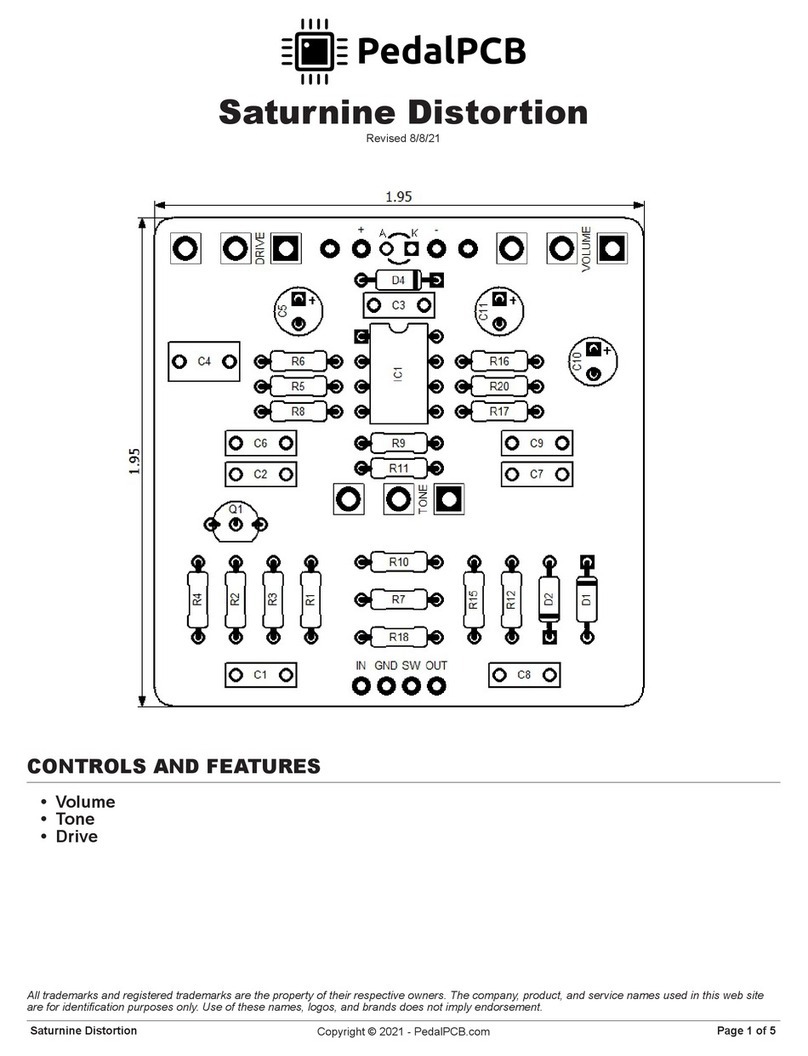
PedalPCB Saturnine Distortion Wiring diagram
FuzzDog
FuzzDog Klone V4 manual
thomann
thomann Harley Benton Classic Chorus user manual
Voodoo Lab
Voodoo Lab PEDAL POWER DIGITAL user manual
Fractal Audio
Fractal Audio AXE-FX II Quick reference guide
Zoom
Zoom Guitar Effects Console G9.2tt2q Operation manual
