Shift Line Prism II User manual
Prism II Stereo Filter-Pad
User Guide

Table Of Contents
Connections 3
Connection Options 3
MONO Mode 3
MONO TO STEREO 3
STEREO / DUAL MONO Mode 4
DOUBLE PROCESSING Mode 4
Controls 4
The STEREO Knob 6
Bypass and Indication 6
ON/HOLD LED 6
TAP/ALT LED 7
Prism II: Signal Path 7
LFOs 8
Modulation Rate Setup 9
Banks & Patches 9
Blue Bank 9
Red Bank 10
Magenta Bank 10
Cyan Bank 11
Favorite Preset 11
Detune Mode (Gradual Signal Detuning) 12
EXT.TAP — External Control 12
Working with the Config File 13
Fine-Tuning via USB 13
Introduction 13
General Settings 13
Firmware Version & Rules 13
BEAT Switch Settings 14
Program Switching Settings 14
EXT.TAP (External Parameter Control) Settings 14
MIDI Config 15
Favorite Preset Control Settings 15
Patch Settings 15
Patch Position in Banks 15
Input and Output Level Settings 16
Additive Synthesis Section 16
Filter Blocks 17
Modulation Settings 17
Reverb Settings 18
LFO Settings 19
Saving Parameters and Configs 20
Reverting to Default Settings 20
MIDI Config 20
MIDI Implementation Chart 20
Updating the Firmware 21
Specifications 22

Connections
●LEFT IN is a monophonic signal input. In a mono signal chain, use this input exclusively.
●RIGHT IN is an input for the second signal source. A stereo setup can be achieved by simultaneously connecting
two mono signal sources to the LEFT IN and RIGHT IN inputs. The Prism II does not support TRS connections.
●LEFT OUT is the left channel output. Connect it to the signal receiver. In a mono signal chain, use this output
exclusively.
●RIGHT OUT is the right channel output. Connect it to the signal receiver. A stereo setup can be achieved by
simultaneously connecting the LEFT OUT and RIGHT OUT outputs to two mono inputs. The Prism II does not
support TRS connections. The mono and stereo modes are described in detail further on.
●EXT. TAP is an input for external control: MIDI Type A, passive footswitch (normally open momentary button) or
analog triggers (S-trig/V-trig). The EXT. TAP functions are described in detail further on.
●POWER IN is a power supply input (9-12VDC).
●Micro-USB is a port for connecting the pedal to a computer for servicing, configuration and mode switching.
Connection Options
MONO Mode
LEFT IN is the main input. If you are using the pedal with a mono
signal source, use that input exclusively. Connect the signal
source to the LEFT IN input, then connect the LEFT OUT output to
the signal receiver. Using RIGHT IN in mono setups is not
recommended.
MONO TO STEREO
In order to convert a mono signal to stereo, connect the signal
source to LEFT IN (the main input jack), then connect LEFT OUT
and RIGHT OUT to the signal receiver. The dry signal will be
placed in the center, while the wet signal will be spread across the
stereo image depending on the STEREO knob’s position.
STEREO / DUAL MONO Mode
When both LEFT IN and RIGHT IN are engaged, the pedal goes
into dual mono mode and the channels are processed
independently.
The dry signal in the left channel goes to LEFT OUT while the dry signal in the right channel goes to RIGHT OUT. In
this mode, you can plug either a stereo source or two mono sources into the pedal. The two mono sources will be
processed in parallel.
DOUBLE PROCESSING Mode
The Prism II has no audible delay effects; however, it has four
resonant filters.
WARNING! Using the double processing mode IS NOT RECOMMENDED. This type of connection will create a
feedback loop, causing the pedal to immediately go into self-oscillation which may damage your hearing and/or
speakers. Be careful to never use this connection type unless you’re 100% sure it is the desired effect.

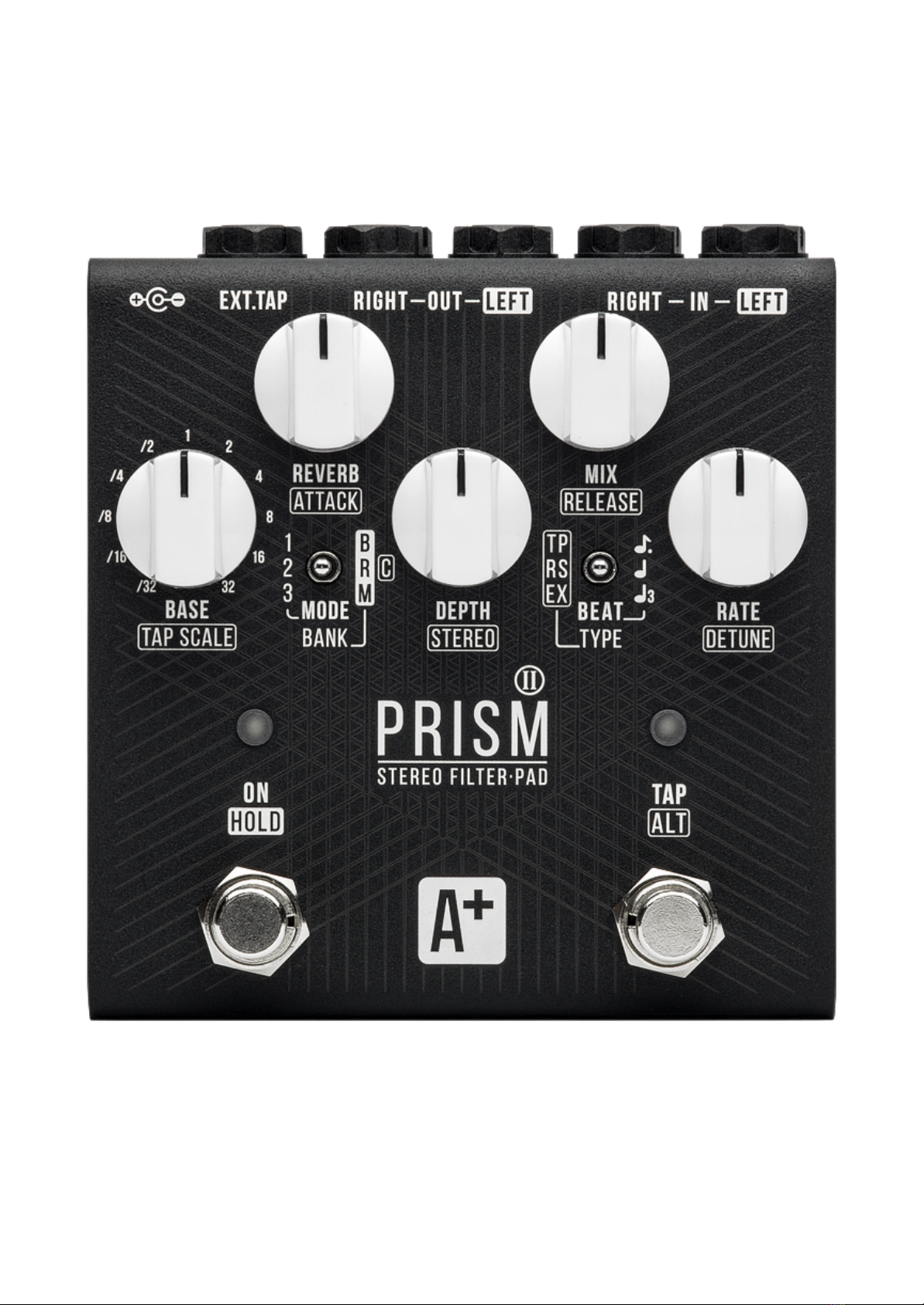
Controls
The Prism II has dual-function controls: each knob and switch can have several purposes. Primary functions are
printed in white on the pedal (and in bold in this text). Secondary functions which can be accessed by holding down
the TAP (ALT)footswitch are printed in a white border on the pedal (and are underlined in this text). The functions
which can be accessed by holding down the ON (HOLD)footswitch are printed in black-on-white on the pedal (and in
italics in this text).
●The BASE knob sets the base filter frequency value. In most cases, the LFO oscillates between the minimum and
maximum values. The BASE knob sets the minimum value (frequency) for the device’s filters.
●The DEPTH knob sets the maximum filter frequency value (the filter’s frequency mod depth). The higher this
value, the more impact the LFO has on the BASE knob (movement of the base filter value across the frequency
range). Set the DEPTH knob fully CCW for static filters or fully CW to make them move from the min value to the
max.
●The RATE knob determines the speed at which the filters move along the LFO shape. The range is 60 to 0,125
seconds (0,01666(6)Hz – 8Hz). The BEAT switch provides additional control over this range.
●The REVERB knob controls reverb decay time. Turn this knob fully CCW to disengage the reverb block. The reverb
to dry signal ratio is fixed for each algorithm, but turning the REVERB knob allows you to go all the way from
slight signal coloration to huge pad-like tails.
●The MIX knob controls wet signal volume. The Prism II was designed as a send effect where the processed
signal is mixed in with the dry one; however, you can use the Kill Dry mode to exclude the dry signal from the
output. In Kill Dry mode, the MIX knob controls output volume.
●The MODE switch selects the algorithm (patch). For a detailed description of patches, please refer to the “Banks
& Patches” section.
●The BEAT switch selects a subdivision for the time set by the TIME knob or the TAP footswitch:
○UP: 3/4 (dotted eighth note).
○CENTER: 1/1 (quarter note).
○DOWN: 2/3 (quarter note triplet).
The subdivisions can be altered via the config file.
●The ON (HOLD) footswitch has multiple functions:
○Press once to turn the effect on or off.
○Press and hold to go into Detune Mode (gradual detuning of the signal at a set rate).
○Press twice to recall the Favorite preset or switch back to live control.
○Press and hold while changing the MODE switch setting to select the bank (this behavior can be changed
via the config file).
○Press and hold while changing the BEAT switch setting to select bypass mode and control the Kill Dry
function.
●The TAP (ALT) footswitch has multiple functions:
○Press twice to set LFO rate.
○Press and hold the TAP and ON footswitches simultaneously for 3 seconds to record the current settings as
a Favorite preset.
○Press to access the secondary functions printed in blue.
○Press and hold while in EX mode to trigger the expression pedal simulation envelope.
○Press and hold while changing the MODE switch position to access the Cyan bank.

Press and hold the ON/HOLD footswitch:
●While changing the BANK switch position to select a patch bank (each bank holds 3 patches):
○UP: the Blue bank.
○MIDDLE: the Red bank.
○DOWN: the Magenta bank.
For a detailed description of the banks, see the “Banks & Patches” section.
●While changing the BEAT switch position to select the bypass mode:
○UP: “No tails” mode.
○MIDDLE: “Tails” mode.
○DOWN: “Kill Dry with tails” mode.
For a detailed description of the modes, see the “Bypass and Indication” section.
Press and hold the TAP/ALT footswitch:
●While changing the TYPE switch position to select one of the three global modes:
○TP: tap tempo mode. LFO rate is controlled by the RATE knob or the TAP footswitch.
○RS:the RATE knob controls LFO rate; LFO phase is reset to zero with every press of the TAP
footswitch.
○EX:expression pedal simulation mode. LFO MAIN is turned off and the movement across the
frequency range is controlled by ATTACK and RELEASE times. In this mode, the BASE knob sets the
minimum value of the virtual expression pedal, while the maximum value is controlled by the DEPTH
knob. The envelope is triggered upon pressing the TAP footswitch. Press and hold the TAP footswitch
to enter the envelope’s hold stage.
●While turning the TAP SCALE knob to scale the tempo set by the TAP footswitch, which operates in the 0.2 –
2s range. In tap tempo mode, scaling the tempo this way lets you access tempos that are inconvenient to tap
in. The available division/multiplication range is 2x to 32x. Turn the knob CCW to slow the LFO rate down
(divide) or CW to speed it up (multiply).
●While turning the STEREO knob to control stereo width. The knob’s main function is to offset LFO phase in
one of the channels. Offset depth varies from patch to patch, depending on the initial settings. The higher the
setting, the wider the stereo field.
●While turning the DETUNE knob to control the depth of gradual wet signal detuning in Detune Mode
(accessed by pressing and holding the HOLD (ON) footswitch).
●While turning the ATTACK knob to set attack time in EX mode.
●While turning the RELEASE knob to set release time in EX mode.
●While changing the BANK switch position to access the patches in the Cyan bank. For a detailed description
of the banks, see the “Banks & Patches” section.
In TP (tap tempo) mode, the LED over the TAP/ALT footswitch glows magenta when you press and hold the footswitch.
It indicates that secondary functions of the controls are being accessed.
Tweaking the secondary control functions (underlined in this text) will have no effect on the primary control function
values (printed in bold in this text), and vice versa.
The primary and secondary functions are independent from each other, but only the latest one you’ve tweaked will
have a physical representation (because they are controlled by the same knob or switch).
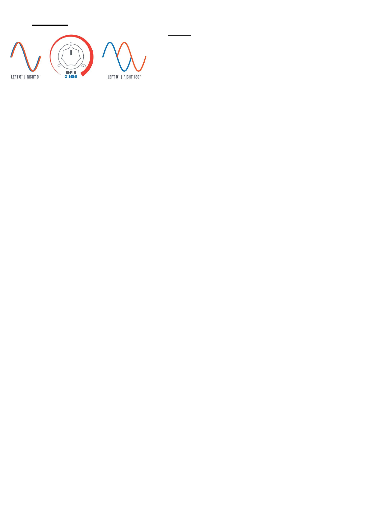
The STEREO Knob
The STEREO knob affects LFO phase in the right channel. As a
secondary function, it is accessed by holding down the ALT/TAP
footswitch.
Set the knob fully CCW to have the phases perfectly in sync. In the
fully CW position, the phase is offset by 180 degrees. Keep in mind
that phase offset values can be different from 0 in various elements
of the signal chain; this means that the STEREO knob will either
“expand” the stereo stage or move the elements to different positions in the stereo field, depending on the patch.
Bypass and Indication
The dry signal path is fully analog throughout the whole pedal. No distortion is applied to the dry signal. Due to the
Prism II’s active bypass, there is no audible clicking, and three independent global modes are available (selectable by
the BEAT switch while holding down the ON footswitch):
●UP: “No tails” mode. The effect is only heard when the pedal is engaged in the signal chain and turns off
immediately when the ON footswitch is pressed.
●CENTER: “Tails” mode. After you have switched the pedal off via the ON footswitch, it keeps playing reverb
reflections but the incoming signal is no longer processed.
●DOWN: “Kill Dry with tails” mode. The dry signal is completely removed from the output. Just like the previous
mode, this one only engages the input when you press the ON footswitch. The reverb tails are played till the end,
so that the sound doesn’t get cut off abruptly. This mode is highly recommended when using the Prism II as an
insert effect (where only the wet signal is needed) or in external wet/dry mixing setups.
The bypass mode is displayed upon selection and upon power-up. The LED above the ON footswitch flashes five
times in one of the following colors:
●Red: “No tails” mode.
●Blue: “Tails” mode.
●White: “Kill Dry with tails” mode.
ON/HOLD LED
The ON/HOLD LED has five functions:
1. On/off indication. If the pedal is bypassed (disengaged from the signal chain), the LED doesn’t light up.
2. Active bank indication. Upon power-up, the LED displays the selected bank: Blue, Red, Magenta or Cyan.
3. Detune Mode status indication. When the ON/HOLD footswitch is held down, the LED flashes in various colors.
4. “Favorite” status indication. When the Favorite preset is recalled, the ON/HOLD LED glows green. If the pedal is
bypassed, the LED flashes briefly to indicate that the Favorite preset will be active when the pedal is turned on. If
the Favorite preset has been changed but not saved, the LED flashes briefly.
5. Bypass mode indication upon selection or power-up.
TAP/ALT LED
The TAP/ALT LED has four functions:
1. Tempo indication. The TAP LED flashes in sync with the current tempo, taking the BEAT switch and TAP SCALE
knob values into account.
2. USB connection indication. The TAP/ALT LED flashes blue/”current mode” when the pedal is connected via USB.
3. TP mode indication. The TAP/ALT LED lights up in magenta in this mode. It also indicates that secondary
functions (printed in blue) are being accessed.
4. Global mode indication:
●White: TP (tap tempo mode).
●Red: RS (LFO reset mode).
●Yellow: EX (expression pedal simulation mode).

Prism II: Signal Path
The signal path for each of the two channels looks like this:
The incoming signal goes into the three-channel pitch shifting section (octave down, fifth up, octave up). Each of the
three channels has its own low-pass filter (LPF) and can be mixed in with the dry signal; the dry signal can also be
excluded from the mix in Kill Dry mode. Marked with a dotted blue line in the schematic, the pitch shifting section is
additive: it adds new “colors” to the incoming signal. The output of this section goes into the first filter.
All the four filters are identical, each one consisting of a splitter, three filter channels and a mixer. The processed
signal can be mixed with the dry one via the cross-mixing section (filter output can also be subtracted from the dry
signal at a desired ratio).
Each of the three filter channels has a 12dB/Oct slope and controllable resonance:
●The low-pass filter (LPF) cuts off the high frequencies.
●The band-pass filter (BPF) cuts off the low and high frequencies.
●The high-pass filter (HPF) cuts off the low frequencies.
Each of the filters can be offset from the frequency set by the BASE knob. Additionally, each filter has a ratio by
which it is affected by the DEPTH knob. This allows the filters to move in and out of sync, and also in opposite
directions. Combined with the cross-mix, these filter interactions can result in numerous sonic flavors ranging from
classic “wah” sounds to complex notch filtering and even phasing. Since each of the two channels has its own set of
four filters, the Prism II has a very broad sonic palette.
After the two filter blocks, the signal goes into the modulation section.
The mod section has its own LFO which runs independently from the main rate settings. This way, the signal “has a
mind of its own” and doesn’t just follow the main LFO. Depending on the cross-mix section settings, the modulation
blocks can allow you to achieve simple 2-voice chorus effects, vibrato, mild flanging, or anything in between. There
are two modulation blocks, and each one can have different settings.
Following the pitch shifting section, the two filters and the first mod block, the signal goes into the reverb section.
That’s where the real fun starts! Interface-wise, the whole section is represented by a single knob which controls
reverb decay. Each patch has its own dry/reverb mix, but reverb decay can be controlled over a very wide range of
values. When the knob is fully CCW, the reverb section is effectively disengaged; turning the knob fully CW results in
multiple overtones and slowly decaying reflections. The reverb section can be viewed as an envelope generator in a
virtual synth: it allows the attack, hold and release stages to be controlled simultaneously. The resulting sound
greatly depends on which filter blocks (pre/post-reverb) are engaged. Yes, there are two more filters after the reverb
block!

The second filter group and mod section are functionally identical to the first ones, but their impact on the sound is
dramatically different. By using both filter groups at once or only one of them, you can achieve substantial variations
in sound; even more so if you throw modulation into the mix.
The shelving HPF is the final touch to the signal chain. It prevents the Prism II from destroying your lows by reducing
the impact of resonant peaks in the lower frequency range.
Following all the processing, the resulting signal goes into the output mix section, where it is mixed with the dry
signal via the MIX knob. In Kill Dry mode, the MIX knob acts as the output volume control.
The Prism II has 12 algorithms (patches). Each patch may or may not use all of the device’s signal chain elements.
The Prism II patch library will be expanded over time; additionally, you can try programming your own algorithms
through the config file.
We are going to publish new patches on the Prism II support page and on social media, so stay tuned.
LFOs
The Prism II has four LFOs. Three of those control filter frequency and stereo width, while the fourth one controls
modulation. The rates for two of the LFOs are set by the RATE knob or TAP footswitch. The diagram and description
below will let you visualize the interactions better.
A complex set of LFO waves with extra waveshaping and cross-modulation controls filter cutoffs and movement in
the stereo field.
●LFO MAIN: triangle wave; rate is set via the RATE knob or TAP footswitch. This LFO controls the overall
movement but can be altered by LFO2 and LFO3, as well as by the LFO COMMON settings. This LFO’s phase
is reset when you turn on the effect and press the TAP footswitch.
●LFO2: sine wave; rate and amplitude are set via the config file (this LFO has no physical controls). This wave
is summed with LFO MAIN, adding some controlled chaos to its movement. Some patches don’t use this LFO.
●LFO3: saw/random wave; rate is linked to LFO MAIN rate at a certain ratio (such as 1/2x, 3x or 4x). This LFO
affects the other LFOs’ amplitudes by the following formula: LFO3*(LFO2+LFO MAIN). The result goes to LFO
COMMON, where it gets clipped by the limiter.
●LFO COMMON distorts the incoming wave, turning it into a trapezoid wave (at values 1.1–3) or an “almost
square” wave (at values 4–1000). This parameter is smoothed by a filter, which can let you achieve glide
effects.
LFO2 and LFO3 affect LFO MAIN at a set ratio and have extra settings in the config file. In EX mode, LFO MAIN is
disengaged and replaced by the ATTACK and DECAY parameters.
MOD LFO is configured via the config file and has no physical controls. Its main purpose is soft modulation, which is
set differently for every patch.
Modulation Rate Setup
Use the RATE knob or TAP footswitch to set the mod rate in quarter notes, then use the BEAT switch if you wish to
turn those into triplets or dotted 8ths. You can also set your own tap division values through the config file. The TAP
LED displays the set LFO rate. The range of the RATE knob is 60 to 0.125s (0,01666(6) – 8Hz); the set rate can be sped
up via the BEAT switch.

The TAP footswitch and the RATE knob have the same effect on modulation rate, which is determined by the control
that has been used last.
The TAP footswitch operates in the 0.2 – 2s range. Additionally, the TAP SCALE knob can be used in TP mode to
divide or multiply the rate by fixed values between 2x and 32x. Turn the knob CCW to slow the LFO rate down (divide)
or CW to speed it up (multiply).
In EX mode (expression pedal simulation), filter cutoff movement is controlled by the ATTACK and RELEASE knobs;
LFO MAIN is disengaged in that mode. An AHR (attack/hold/release) filter envelope is triggered upon pressing the
TAP footswitch. As long as you hold the TAP footswitch down, filter cutoff will stay at the value determined by the
DEPTH knob.
Banks & Patches
The patches are organized into 4 banks, each holding 3 patches.
To select a bank, press and hold the ON footswitch and move the MODE/BANK switch to the desired position:
●UP: Blue Bank (the ON LED glows blue).
●MIDDLE: Red Bank (the ON LED glows red).
●DOWN: Magenta Bank (the ON LED glows magenta).
After that, you can release the ON footswitch and use the MODE switch to navigate within the bank.
To select patches from the fourth bank (Cyan Bank), press and hold the TAP footswitch and move the MODE/BANK
switch to any position. After that, you can release the TAP footswitch and use the MODE switch to navigate within
the bank.
The config file provides access to another way of selecting patches.
All patches have been significantly reworked compared to those found in the Prism-9. Some of the algorithms have a
similar character to the original ones, but their functionality has been greatly improved.
Blue Bank
The ON LED glows blue.
MODE switch position:
●UP: Synthation Flow
“The Prism at its finest”. This patch pays homage to Michael Garrison — particularly to his “Images” album which
still sounds amazing 35 years since its release. Finally, this kind of sound is available in a simple guitar pedal.
All three octaves and a fifth are used in the pitch shifting section. Only the pre-reverb filter block is engaged,
resulting in mild filtering with barely noticeable movement. The reverb sounds soft but completely replaces the
dry signal. All those elements together create a lush pad for the incoming signal. This patch is probably the
closest one could get to the original Prism-9.
●MIDDLE: Shu Melody
With its clear sound and mild post-reverb filtering, this patch works great for melodic lines where you might want
a soft pad which doesn’t get too crazy. The reverb smoothens the tone, while the rather simple LFO wave is
handy if you want to boost mod rate into the audio range via the BEAT switch. This patch works best in Kill Dry
mode.
●DOWN: CM116
Another classic sound: this time, you can use your guitar or bass to get tones reminiscent of Tangerine Dream.
LFO wave multiplication is quite uncommon in the guitar world. The incoming signal is enriched and expanded
by the pitch shifting section. Both the pre- and post-reverb filter blocks are used; those aren’t fully mixed in with
the dry signal, resulting in a well-balanced sound. LFO2 is 32 times faster than the main one, so you can get
rhythmic patterns at low values of the RATE knob or constant filter movement at higher ones.

Red Bank
The ON LED glows red.
MODE switch position:
●UP: BUTTER
The mild filtering in this patch works best with a slow LFO set at medium depth. The algorithm features a bit of
upper and lower octave signals. One of the filters moves in the opposite direction to the others, adding some
instability to the sound. The reverb is turned up high in the mix and has a long decay, resulting in a soft pad with
prolonged attack and release times. Coupled with the reverb, the slow and shallow modulation creates
noticeable pitch warbles.
●MIDDLE: MS20X3
To a certain extent, this patch pays homage to the MS20 filter. Three of the filters are set to highlight various
harmonics (with resonant peaks at +12 and +19 semitones); the fourth filter provides smoothness to the overall
sound. Stereo modulation creates a constant movement. The reverb is mixed in with the main signal without
overpowering it. This patch works particularly well in Kill Dry mode with a harmonically rich incoming signal
(such as distorted guitar). Depending on rate settings, you can get classic filter sweeps or alien signals from this
algorithm.
●DOWN: CM122 + RND
Another variation on the CM116/Tangerine Dream sound — with some extra tricks up its sleeve. In this patch, 16
random steps are multiplied by the main rhythm, making it more expressive and unpredictable. Filter effects are
more pronounced here; both the pre- and post-reverb filter blocks are still used. The reverb is turned down a bit
to highlight the stepping sequence in the filter mod.
Magenta Bank
The ON LED glows magenta.
MODE switch position:
●UP: MEOW
The name speaks for itself: this patch can meow like a clowder of cats. The frequencies highlighted by the filters
have different LFO depths. This algorithm combines long reverb decay with soft spatial and temporal
modulation. The patch can be used with little to no filter movement for endless ambient soundscapes.
●MIDDLE: Illusions Far
This inspiring algorithm is reminiscent of your favorite childhood toy. It sounds as if a swarm of tiny robots is
transposing the sound in a way that the incoming signal is pretty much eliminated. The sound is then processed
by HPFs set to medium resonance and low depth. The soft modulation and soothing reverb provide the finishing
touches. The DETUNE mode is particularly pronounced in this patch.
●DOWN: Robot in my head
This algorithm employs pitch shifting and ring modulation in LFO2 and LFO3; the RATE knob controls the tone.
The parallel reverb processing in the patch retains the incoming signal’s attack. The signal itself is significantly
colored and expanded by the pitch shifting. Due to the constant movement across the stereo field, the
separation between the incoming signal and the generated pitches is even more noticeable. Try setting the BASE
knob to low values with slow filter movement, then change the speed to several Hz via the RATE knob. Also, don’t
hesitate to try out the extreme knob positions.

Cyan Bank
Use TAP + MODE to switch to this bank. The ON LED glows cyan.
MODE switch position:
●UP: STATIC
This electrified patch features ring modulation in the reverb, the mod sections, and LFO2. The effect is
particularly pronounced at higher REVERB knob values. The post-reverb filters have mild settings which allow
reverb tails to stay audible after the filters are closed; this works great in all modes, including the EX mode
(virtual expression pedal). The name “STATIC” is not only a nod to electricity but also a hint that the algorithm
sounds really nice even with no filter mod (with the RATE knob fully CCW).
●MIDDLE: Dawn at the mirror lake
This sound is reminiscent of points of light dancing on the water on a warm summer day. The movement of
resonant filters is intertwined with the warm reverb texture. Combined with a somewhat unpredictable LFO
shape, the bright filters create complex patterns with airy, flanger-like modulation. The reverb adds to the “crystal
clear” sound, which is gradually moving across the stereo field. The algorithm’s pronounced character can be
tamed via the BASE and DEPTH settings.
●DOWN: Broken Tape Reverb
A slow descent into eternity, which has somehow been recorded on an old VHS tape. This peculiar sonic
character stems from a combination of unorthodox techniques, such as out-of-phase filters and deep reverb
modulation. The pitch shifting section creates a sort of “echo” with characteristic artifacts. Finally, LFO3 in
stepped random mode imitates a broken tape mechanism with different settings for each of the two channels.
Favorite Preset
In order to store the current settings into a Favorite preset, press and hold the TAP footswitch and the ON footswitch
simultaneously for 3 seconds. The preset will be recorded into the pedal’s internal memory, and the ON LED will light
up in green.
To recall or exit the Favorite preset, briefly press the ON footswitch twice. If the ON LED is glowing green, the Favorite
preset is active. If the Favorite preset has been recalled but the pedal is bypassed, the ON LED lights up briefly: this
provides visual feedback regarding the settings which the pedal will employ when engaged.
When a Favorite preset is active, controls on the pedal have no effect until you turn/switch them. When a control
setting has been changed, the ON LED flashes briefly to indicate that the new settings haven’t been saved yet. To
save the changes, press and hold the TAP and ON switches simultaneously for 3 seconds. If you exit the altered
Favorite preset without saving, the changes you made won’t be recalled the next time you activate the Favorite
preset.
When the Favorite preset is active, there is no bank indication. All settings (including bypass settings, global mode and
modulation rate) are saved in the Favorite preset.
You can turn off the Favorite function or remap it to the EXT.TAP input through the config file. Read more about Favorite
preset settings on the Prism II Support Page.
Detune Mode (Gradual Signal Detuning)
The Detune Mode only affects the pitch shifting section. If the pitch shifting section isn’t engaged in the patch, the
Detune Mode has no effect.
To enter Detune mode, press and hold the ON/HOLD footswitch for at least 0.3 seconds. The gradual signal detuning
will manifest differently depending on the patch. The more transposed signal the patch employs, the more
pronounced the detuning will be.
The DETUNE knob (ALT+RATE) controls the depth of the detuning effect.

EXT.TAP — External Control
The EXT.TAP jack is an input for external control over the Prism II’s parameters. It has several operation modes:
●Passive controller (normally open momentary button). This mode precisely copies the functions of the TAP
footswitch and is active by default.
●S-trigger — “short circuit trigger”, analog trigger/gate with the same polarity as the pedal’s. This is the
recommended trigger type. Use the config file to select this operation mode. Two sub-modes are available:
○The TAP footswitch retains its functions even when the clock signal is connected.
○The TAP footswitch is only active in EX mode and can be used to access secondary control functions in any
mode; all of its other functions are transferred to the external clock source.
●V-trigger — “voltage trigger”/”positive trigger”, analog trigger/gate with polarity opposite to the pedal’s. If no
external signal is coming into the EXT.TAP input, the LED will light up, and some of the pedal’s functions will be
inactive. Those functions become active as soon as a clock signal is connected. Use the config file to select this
operation mode. Two sub-modes are available:
○The TAP footswitch retains its functions even when the clock signal is connected.
○The TAP footswitch is only active in EX mode and can be used to access secondary control functions in any
mode; all of its other functions are transferred to the external clock source.
Use this trigger type if you have no S-trigger source or if you prefer V-triggers for other reasons.
●Full MIDI control (Type A).
●Favorite preset control. Use a passive controller (a quick tap on a normally open button) or an S-trigger signal to
recall or exit the Favorite preset. To record a new Favorite preset, send an active Gate signal into the pedal or
hold down the external controller for over 3 seconds.
In order to sync LFO phase with the tempo of the song, make sure to press the ON footswitch on time. When the
pedal is engaged, LFO phase is reset to the initial values determined by the active patch.
The S-trigger mode is active by default due to its equally good response to passive and active control via the EXT.TAP
input. In order to switch external control mode to passive controller, V-trigger or MIDI, use the config file as described
further in this manual.
The passive and active (S-trig/V-trig) external control options assume full control over the TAP footswitch’s
functions, as determined by the global mode:
●TP: they set LFO rate (replacing the RATE knob).
●RS: they “press” the TAP footswitch to reset LFO phase.
●EX: they “hold down” the TAP footswitch as long as the Gate signal is active.
The active modes can work both with triggers and gates. Gate signals are crucial for expression pedal simulation
(the EX mode).
To connect a MIDI signal source, use a 6.3mm Type A stereo jack (TRS). The MIDI channel is set in the config file. In
MIDI mode, delay time is set by the last control you’ve interacted with (MIDI Clock, TIME knob or TAP footswitch).
The MIDI Start command can be used to reset the LFO externally.
The pedal is designed to be clocked in quarter notes with time between two control signals ranging from 0.005
seconds to 2 seconds. The lowest BPM is 30. The stable BPM range is 30 to 300. The accuracy depends on the
stability of the incoming clock signals.

Working with the Config File
Fine-Tuning via USB
On the right side of the Prism II, you can find a microUSB port which lets you connect the pedal to your computer. To
do that, you need a microUSB cable (purchased separately). The USB port on your computer should be USB 2.0 or
higher.
NB! Before performing any actions with the PRISM 2 drive, make sure the cable is fully functional and there are no
interruptions in the connection.
Connect the cables in the following order:
●Connect the power supply to the Prism II.
●Connect the Prism II to your computer with a microUSB cable.
●If the connection is successful, a PRISM 2 drive will appear on your computer. This means the pedal is ready for
further operations.
●Before disconnecting the microUSB cable from the pedal/computer, make sure to safely eject the drive first.
●Do not disconnect the microUSB cable until all operations with the PRISM 2 drive have been finished!
Introduction
The device’s flash drive has an AFXSETUP folder which contains the PRISM2.SET file. The file can be viewed and
edited in any text editor: simply right-click on the file and select an editor to open it with (you can also configure your
system to open *.SET files with your text editor of choice).
The PRISM2.SET file is a set of configurations which the pedal accepts to edit the sound processing programs. We
recommend editing the config file to users with at least a basic programming background.
While editing the PRISM2.SET file can go wrong (by entering improper values or erasing vital data, for instance), no
harm will be done to the pedal itself. Simply delete the “bad” file, eject the Prism 2 drive, unplug the power supply
from the pedal, then plug it back in. This will make the Prism II generate the default config file again.
If you’re still reading this, you are probably ready to enter the magic world of fine-tuning sound processing programs.
Give it a try: the config file has a number of useful features which cannot be accessed via the pedal’s physical
controls.
General Settings
Firmware Version & Rules
The first segment of the file displays the current firmware version and the formatting rules:
/* Prism II
* Hardware Ver. 1.2.7
* Software Ver. 1.3.0 2022-05-01
* parameter lines must begin with #
* parameter names are not case sensitive
* format: #parameter_name value_digits
*/
BEAT Switch Settings
TAP TEMPO subdivisions for the BEAT switch. You can use any values in the 0–1.0 range; however, we recommend
using rhythmically connected ones:
; Beat switch

#GLOBAL_TAP_UP 0.75
#GLOBAL_TAP_CENTER 1.0
#GLOBAL_TAP_DOWN 0.666666688
Any changes you make to the config file become active as soon as the pedal rescans the file. In order to hear the
changes on the fly, simply save the config file, change the position of the MODE switch, then put it back to its original
position.
The #GLOBAL_TAP_UP parameter defines the UP position of the BEAT switch; by default, it is a dotted 8th (0.75). The
CENTER position is a quarter note (1.0, #GLOBAL_TAP_CENTER). The DOWN position is a quarter note triplet
(0.6666666, #GLOBAL_TAP_DOWN). We recommend leaving any one of those values at 1.0 and altering the other two
as needed. For instance, try setting the value to 0.5 (8th note), 0.25 (16th note) or 0.125 (32nd note). You can also
experiment with more exotic subdivisions such as 5/8 (0.625), 7/8 (0.875), 5/6 (0.833333334), and so on.
Program Switching Settings
Patch (program) switching parameter:
#GLOBAL_MODE_SWITCH 1
This block determines the algorithm of switching among different patches. By default, the “bank” mode is on (the
value is set to 1): hold down the BYPASS footswitch and use the MODE switch to select the bank, then use the MODE
switch on its own to select a patch within the bank. To select patches from Bank 4, use the TAP footswitch and the
MODE switch.
When the value is set to 0, selecting the patch is done by BYPASS + MODE (to select a patch from the Red bank), TAP
+ MODE (to select a patch from the Magenta bank), or TAP + BYPASS + MODE (to select a patch from the Cyan bank).
To select a patch from the Blue bank, use the MODE switch on its own.
NB! On the Prism II Black Edition, the BYPASS/DETUNE footswitch is labeled as ON/HOLD.
EXT.TAP (External Parameter Control) Settings
#GLOBAL_JACK_EXT_TAP 1
By default, the #GLOBAL_JACK_EXT_TAP has a value of 1, which allows the pedal to be used both with passive and
active external clock sources.
Choose the value for this parameter according to your needs:
●0— Use this value if you only want to use the pedal with a passive external controller (a normally open
momentary button). With this setting, the EXT.TAP signal has the exact same functions as the TAP footswitch.
●1— Use this value if you plan to use an S-trigger (“short circuit trigger”, analog trigger/gate). This trigger type is
preferable; it has the same polarity as the pedal. The TAP footswitch retains its functions even when a clock
signal source is connected to the pedal.
●2— Use this value if you plan to use an S-trigger (“short circuit trigger”, analog trigger/gate). Unlike the previous
setting, this value only allows the TAP footswitch to access secondary functions but not to affect the primary
ones.
●3— Use this value if you plan to use a V-trigger (“voltage trigger”/”positive trigger”, analog trigger/gate). This
trigger type has a polarity opposite to the pedal’s. When no external signal is coming into the EXT.TAP input, the
TAP LED will glow and some of the pedal’s functions will be inactive. As soon as a clock signal is connected to
the pedal, those functions will become active again. The TAP footswitch retains its functions even when a clock
signal source is connected to the pedal.
●4— Use this value if you plan to use a V-trigger (“voltage trigger”/”positive trigger”, analog trigger/gate). Unlike
the previous setting, this value only allows the TAP footswitch to access secondary functions but not to affect
the primary ones. Use this trigger type if you have no S-trigger source or if you prefer V-triggers for other reasons.
●10 — Use this value if you wish to control the pedal via MIDI.
The pedal is designed to be clocked in quarter notes with time between two control signals ranging from 0.005
seconds to 2 seconds. The lowest BPM is 30. The stable BPM range is 30 to 300. The accuracy depends on the
stability of the incoming clock signals.

MIDI Config
The MIDI channel which the pedal responds to.
#MIDI_CHANNEL 1
Accepted values: 1 to 16.
MIDI Clock configuration.
#MIDI_CLOCK_ENABLE 1
●0 — MIDI Clock messages are not accepted. The device uses internal clock instead.
●1 — MIDI Clock messages are accepted (enabled by default).
MIDI Program Change (PC) configuration.
#MIDI_PC_ENABLE 1
●0 — PC messages are not accepted.
●1 — PC messages are accepted (enabled by default).
The device accepts 12 programs (0 to 11).
Favorite Preset Control Settings
The device allows you to control the Favorite preset via the EXT.TAP input. To do that, set the
#GLOBAL_JACK_EXT_TAP parameter’s value to 30. A passive controller (normally open momentary button) or an
active S-trigger/gate signal will do the job.
Press the external controller briefly to enter or exit the Favorite preset. Press and hold the external controller for over
3 seconds to save the settings as the Favorite preset. In this mode, both of these functions are triggered when the
button is released.
#GLOBAL_FAV_OFF 0
If you don’t need the Favorite preset option, you can turn it off. Set the #GLOBAL_FAV_OFF parameter’s value
accordingly:
●0 — The Favorite preset is accessible.
●1 — The Favorite preset is inactive (it also cannot be recalled via an external controller connected to the EXT.TAP
input).
Patch Settings
Patch Position in Banks
Patch number:
#PATCH 0
By changing the value from 0 to 11, you can assign the patch to a position in the preset table. When editing the config
file, make sure that no two patches share the same number. We recommend leaving the structure as is and not
changing patch numbers: this will make navigating through the file easier. Patches 0-2 belong to the Blue bank, 3-5 to
the Red bank, 6-8 to the Magenta bank, 9-11 to the Cyan bank. Patch numbers correspond with MIDI Program Change
message values.
Input and Output Level Settings
Input level parameter:
#IN_GAIN 0.25
The #IN_GAIN parameter controls the volume of the input signal. The standard value (1.0) can be increased or
decreased. Decreasing the input gain is needed when using the Prism II in the FX loop of your amp or plugging hot
signals into the pedal (for line-level signals, the recommended value of this parameter is 0.25). Decreasing this value
also lowers the pedal’s output volume, so you’ll have to find the setting that works best for you in the 0.1–1.0 range.

Increasing this value is rarely needed (only when the input signal is very quiet); you can increase the value up to 4.0.
We recommend setting the input gain to no higher than 2.0 to avoid clipping.
Output level parameter:
#OUT_GAIN 2.0
The #OUT_GAIN parameter controls the output volume. Value-wise, this parameter works in the same way as
#IN_GAIN.
Output high-pass filter (HPF) settings:
#OUT_kHPF 0.05
#OUT_sHPF -1.0
The output shelving HPF is mixed in at a negative value. For proper operation, the #OUT_kHPF parameter’s value
needs to be in the 0.0 – 1.0 range; the typical value range is 0.003 (20Hz) to 0.05 (375Hz). The #OUT_sHPF
parameter controls filter effect depth (100% at -1.0, 50% at -0.5) and must always have a negative value in the -1.0 –
0.0 range.
Additive Synthesis Section
The incoming signal goes into a three-channel pitch shifting section: octave down, fifth up, octave up. Each of the
channels has its own LPF and can be mixed in with the dry signal (the latter can also be excluded from the mix).
Signal mixing block:
#MIX_OCTDN_VOL 1.0
#MIX_QUINT_VOL 0.8
#MIX_OCT_VOL 1.0
#MIX_CLEAN_VOL 0.4
The parameters in this block control the volumes of the dry signal and the generated ones: #MIX_OCTDN_VOL for the
lower octave, #MIX_QUINT_VOL for the fifth, #MIX_OCT_VOL for the upper octave, and #MIX_CLEAN_VOL for the dry
signal.
The recommended value range for each of these parameters is 0.0 (removed from the mix) to 2.0 (mixed in at +6dB).
Negative values are not supported.
Signal filtering block:
#MIX_OCTDN_kLPF 0.33
#MIX_QUINT_kLPF 0.1
#MIX_OCT_kLPF 0.1
The parameters in this block control the 6dB/Oct low-pass filters (LPF) of the pitch-shifted signals:
#MIX_OCTDN_kLPF for the lower octave, #MIX_QUINT_kLPF for the fifth, #MIX_OCT_kLPF for the upper octave. The
value range is 0.003 (20Hz) to 1.0 (12kHz). Negative values are not supported.
Filter Blocks
Each of the four filters has the same parameter set with values selected by the same principles. Filter-related
parameters start with #F1_, where 1 is the filter’s number in the signal chain.
The whole set of parameters for a single filter looks like this:
#F1_BLEND 1.0
#F1_SCALE 1.0
#F1_BIAS 0.0
#F1_MIX_LPF 1.0
#F1_MIX_HPF 0.0
#F1_MIX_BPF 0.0
#F1_Q 0.45

#F1_BLEND controls the mix of the dry and filtered signals. At 1.0, the filter is used to the fullest (12dB/Oct); at 0.5, it
is used at half the depth (6dB/Oct); at negative values, the filtered signal is subtracted from the dry one (the effect of
the filter is inverted).
#F1_SCALE controls the scalar range of the LFO’s effect on the filter. At 1.0, the range is 100%; at 0.5, the range is
50%; at 0.0, the filter is static (the DEPTH knob has no effect on filter cutoff frequency). You can use values over 1.0
(but preferably under 2.0) to increase this range, as well as negative values to invert the LFO-controlled movement.
#F1_BIAS shifts the filter frequency set by the BASE knob. It is recommended to keep this parameter’s value under
0.5. Under certain conditions, this parameter can filter out all of the signal, causing it to go silent. The accepted value
range is 0.0 to 1.0 (0.125 = 900Hz). To make a filter static (not affected by the LFO), set this parameter to the needed
value and set the #F1_SCALE parameter to 0.0.
#F1_MIX_LPF controls the mix of the resonant LPF with the dry signal. The value range is 0.0 (0%) to 1.0 (100%).
Negative values are also accepted.
#F1_MIX_HPF controls the mix of the resonant HPF with the dry signal. The value range is 0.0 (0%) to 1.0 (100%).
Negative values are also accepted.
#F1_MIX_BPF controls the mix of the resonant BPF with the dry signal. The value range is 0.0 (0%) to 1.0 (100%).
Negative values are also accepted.
It is possible to select the mix values by ear, although it can yield unpredictable results (particularly with negative
values involved). For a start, it may be easier to use only one filter type in the mix before experimenting with the rest.
#F1_Q controls the filter’s resonant peak. The value range is 0.001 to 1.0. The lower the value, the higher the peak:
+3dB at 0.75, +6dB at 0.5, ~+11dB at 0.25, ~+16dB at 0.125. It is recommended to keep this value over 0.08.
The pedal has four resonant filter sections. You can turn each one on and off independently, as well as set individual
parameters for each of the filters. Experiment away!
Modulation Settings
The pedal has two modulation sections, which are set after the first and second filter groups (as shown in the “Prism
II: Signal Path” diagram). Both sections a controlled by the same LFO which has the following parameters:
#MOD_RATE 4.0
#MOD_PHASE_L 0.0
#MOD_PHASE_R 180.0
#MOD_RATE controls the modulation LFO’s rate (in Hz). The value range is 0 to 4000Hz. Setting the LFO to audio
rates (20Hz and up) can often introduce new audible frequencies into the sound.
#MOD_PHASE_L controls LFO phase for the left channel. The value range is 0.0 to 359.0 degrees.
#MOD_PHASE_R controls LFO phase for the right channel. The value range is 0.0 to 359.0 degrees.
If #MOD_PHASE_L is set to 0.0 and #MOD_PHASE_R is set to 180.0, the STEREO knob expands the stereo stage
(inverted values reverse the movement direction in the stereo field). At other values, the STEREO knob pans the
signal in the stereo field.
Modulation-related parameters start with #MOD1_ and #MOD2_; they are set according to the same principles. Each
group has four parameters:
#MOD1_DEPTH 22
#MOD1_BLEND 0.5
#MOD1_IN_GAIN 1.0
#MOD1_OUT_GAIN 1.0
#MOD1_DEPTH determines mod depth (in samples). The accepted value range is 0 to 511. The higher the value, the
deeper the modulation.
#MOD1_BLEND controls the mix of the dry and modulated signals. The recommended value range is 0.0 to 1.0. At
0.0, the modulation block is disengaged; at 0.5, the mix is 1 to 1 (chorus); at 1.0, only the modulated signal is audible

(vibrato). Values below 0.0 and over 1.0 are also possible. Negative values invert the modulated signal, while values
over 1.0 boost it (+6dB at 2.0).
#MOD1_IN_GAIN controls the input level for the section. This parameter allows you to control the volume of the
signal coming out of the filter mix (or reverb section) before it hits the mod section. The values are set in the same
way as for the #IN_GAIN parameter.
#MOD1_OUT_GAIN controls the output level for the section. This parameter allows you to control the volume of the
signal coming out of the mod section. The values are set in the same way as for the #IN_GAIN parameter.
Reverb Settings
The reverb section has the following parameters:
#RV_BLEND 1.0
#RV_IN_GAIN 0.25
#RV_OUT_GAIN 4.0
#RV_kDK 1.01999998
#RV_SIN0F 2.25
#RV_SIN0R 19
#RV_SIN1F 1.666
#RV_SIN1R 23
#RV_BLEND controls the mix of the dry signal and the reverb. The value range is 0.0 (no reverb) to 1.0 (100% reverb).
The signals are mixed evenly at 0.5. Negative values are accepted but can boost the signal.
#RV_IN_GAIN controls the input level for the reverb section. This parameter allows you to control the volume of the
signal coming out of the filter section. The values are set in the same way as for the #IN_GAIN parameter.
#RV_OUT_GAIN controls the output level for the reverb section. This parameter allows you to control the volume of
the signal coming out of the reverb section. The values are set in the same way as for the #IN_GAIN parameter.
#RV_kDK controls feedback depth. The higher the value is, the quicker the reverb will go into self-oscillation. The
range is 0.0 to 2.0; however, we recommend always starting at 1.0 and tweaking the value to taste. You can also pass
negative values to this parameter in order to invert the phase of the signal. This parameter determines the max decay
value for the REVERB knob.
The reverb tails smoothing section is where the modulation of separate reverb lines is set up. The parameters in this
section determine whether the reverb sounds softer or punchier:
#RV_SIN0F controls the smoothing modulation oscillator rate (in Hz) for the first reverb group.
#RV_SIN0R sets the smoothing modulation depth (in samples) for the first reverb group. Value: 0 – 1000.
#RV_SIN1F controls the smoothing modulation oscillator rate (in Hz) for the second reverb group.
#RV_SIN1R sets the smoothing modulation depth (in samples) for the second reverb group. Value: 0 – 1000.
LFO Settings
The Prism II has three dedicated filter LFOs. The rates for two of the LFOs are set by the RATE knob or TAP
footswitch, while the third one is configured separately for each patch and has no physical controls. The DEPTH knob
sets filter mod depth.
While the LFOs have a wide range of settings, we recommend starting with the basic formula by which the final LFO
shape is calculated:
LFO = (Main LFO + LFO2) * (LFO3 * #LFO3_AMP + #LFO3_AMP_BIAS). If the AMP parameter’s value is 0 and
AMP_BIAS is set to 1, LFO3 has no effect. Otherwise, the sum of Main LFO and LFO2 is multiplied by LFO3.
LFO common parameters:
#LFO_ASCALE 1.409999968
#LFO_kLPF 1.0

#LFO_ASCALE is the multiplier of all LFO element interactions with a limiter set to 1.0. Increasing the value leads to
a greater effect of the limiter on the resulting waveform. Values over 1.0 are recommended. The higher the value, the
longer the filters stay at the lowest and highest points of the wave.
#LFO_kLPF is the slew limiter for the LFO waveform. This parameter allows you to avoid rapid jumps in LFO values.
The lower the value, the smoother the waveform. Smoothing is achieved via a low-pass filter; as a result, subsonic
frequencies can have a substantial effect on the resulting sound. The standard value is 1.0 (no filtering). Set the
value to 0.003 (20Hz) to eliminate the LFO’s effect on the sound. The accepted value range is 0.001 to 1.0.
LFO_MAIN parameters:
#LFO_MAIN_MIN 0.016666651
#LFO_MAIN_MAX 8.0
#LFO_MAIN_PHASE_L 0.0
#LFO_MAIN_PHASE_R 180.0
The MIN and MAX parameters determine the range of the RATE knob.
Recommended values: 0.016666651 – 8.0.
#LFO_MAIN_MIN sets the lowest rate for LFO_MAIN (in Hz). The default value is 0.016666651Hz (~ 1 minute).
#LFO_MAIN_MAX sets the fastest rate for LFO_MAIN (in Hz). The default value is 8Hz.
#LFO_MAIN_PHASE_L determines the phase of LFO_MAIN in the left channel. The value range is 0.0 to 359.0
degrees.
#LFO_MAIN_PHASE_R determines the phase of LFO_MAIN in the right channel. The value range is 0.0 to 359.0
degrees.
LFO2 parameters:
#LFO2_RATE 0.1
#LFO2_AMP 0.1
#LFO2_PHASE_L 0.0
#LFO2_PHASE_R 180.0
#LFO2_RATE sets LFO2 rate. This parameter has no physical controls. The value range is 0.005 to 4000Hz.
#LFO2_AMP sets LFO2 amplitude, which is then summed with LFO_MAIN. The value range is 0.0 to 1.0.
#LFO2_PHASE_L determines the phase of LFO2 in the left channel. The value range is 0.0 to 359.0 degrees.
#LFO2_PHASE_R determines the phase of LFO2 in the right channel. The value range is 0.0 to 359.0 degrees.
LFO3 parameters:
#LFO3_FSCALE 8.0
#LFO3_AMP 0.0
#LFO3_AMP_BIAS 1.0
#LFO3_WAVE 0
#LFO3_PHASE_L 0.0
#LFO3_PHASE_R 180.0
#LFO3_FSCALE is LFO3’s rate scale relative to the tempo set by the RATE knob or TAP footswitch. The value range is
0.001 to 1000. At 0.5, LFO3 is twice slower than the RATE/TAP value; at 3, it is three times faster than the RATE/TAP
value.
#LFO3_AMP sets LFO3 amplitude, which is then multiplied by (LFO_MAIN+LFO2). The value range is 0.0 to 1.0.
#LFO3_AMP_BIAS determines LFO3’s amplitude offset. The value range is 0.0 to 1.0. The sum of #LFO3_AMP and
#LFO3_AMP_BIAS must not exceed 1.0.
#LFO3_WAVE selects LFO3 waveform. The accepted values are 0 (saw wave) and 1 (S&H).
#LFO3_PHASE_L determines the phase of LFO3 in the left channel. The value range is 0.0 to 359.0 degrees.
#LFO3_PHASE_R determines the phase of LFO3 in the right channel. The value range is 0.0 to 359.0 degrees.

Saving Parameters and Configs
Any changes you’ve made to the config file will be accessible to the device after saving. If you want to hear the
changes on the fly, remember to rescan the config file by changing the MODE switch position. The settings saved in
the config file will remain in the pedal until the file is deleted. If needed, make a backup for the file on a different
drive. Ready-made patch sets can be uploaded to the pedal by replacing the config file. The file name (PRISM2.SET)
should not be changed.
Reverting to Default Settings
If you’ve edited the config file and wish to revert to default settings, you can easily restore the default config file.
Simply delete the unwanted config file from the AFXSETUP folder, and the pedal will go back to factory settings.
MIDI Config
The stability of MIDI Clock messages depends on the source, which may or may not be perfect (particularly when
Clock and CC messages are transmitted simultaneously). For best performance, the interval between two
consecutive messages should be set accordingly. We recommend setting the CC message interval to 17-20ms.
The Prism II is connected to the MIDI source via a MIDI Type A 6.3mm TRS jack. The wiring scheme is as follows:
MIDI 4 (Source) > TRS RING,
MIDI 2 (Shield) > TRS SLEEVE,
MIDI 5 (Sink) > TRS TIP.
Read more about MIDI standards here.
You can also use a TS connection (a 6.3mm mono jack into a DIN-5 input). To make such a converter, only use the
following connections:
MIDI 2 (Shield) > TRS SLEEVE,
MIDI 5 (Sink) > TRS TIP.
MIDI Implementation Chart
Table of contents
Other Shift Line Music Pedal manuals


