Shinko LV-300 User manual

1
INSTRUCTION MANUAL
LEVEL SWITCH LV-300
No.LV31JE4 2015.01
To prevent accidents arising from the misuse of this instrument, please ensure the operator
receives this manual.
Safety Precautions (Be sure to read these precautions before using our products.)
The safety precautions are classified into categories: “Warning” and “Caution”.
Depending on circumstances, procedures indicated by Caution may be linked to serious results,
so be sure to follow the directions for usage.
Warning
Warning
•To prevent an electric shock or fire, only Shinko or other qualified service personnel may
handle the inner assembly.
• To prevent an electric shock, fire or damage to the instrument, parts replacement may only
be undertaken by Shinko or other qualified service personnel.
Safety precautions
• To ensure safe and correct use, thoroughly read and understand this manual before using this
instrument.
• This instrument is intended to be used for industrial machinery, machine tools and measuring
equipment. Verify correct usage after purpose-of-use consultation with our agency or main
office. (Never use this instrument for medical purposes with which human lives are involved.)
• External protection devices such as overcurrent protection fuse, etc. must be installed, as
malfunction of this product could result in serious damage to the system.
Also proper periodic maintenance is required.
• This instrument must be used under the conditions and environment described in this manual.
Shinko Technos Co., Ltd. does not accept liability for any injury, loss of life or damage occurring
due to the instrument being used under conditions not otherwise stated in this manual.
Caution with respect to Export Trade Control Ordinance
To avoid this instrument from being used as a component in, or as being utilized in the
manufacture of weapons of mass destruction (i.e. military applications, military equipment,
etc.), please investigate the end users and the final use of this instrument.
In the case of resale, ensure that this instrument is not illegally exported.
Installation precautions
Caution
This instrument is intended to be used under the following environmental conditions
(IEC61010-1): Overvoltage category , Pollution degree 2
Ensure the mounting location corresponds to the following conditions:
• A minimum of dust, and an absence of corrosive gases
• No flammable, explosive gases
• No mechanical vibrations or shocks
• No exposure to direct sunlight, an ambient temperature of 0 to 55 (32 to 131 )
that does not change rapidly, and no icing
• An ambient non-condensing humidity of 35 to 85%RH
• No large capacity electromagnetic switches or cables through which large current is flowing.
• No water, oil or chemicals or where the vapors of these substances can come into
direct contact with the unit
Caution
Procedures which may lead to dangerous conditions and cause
death or serious injury, if not carried out properly.
Procedures which may lead to dangerous conditions and cause
superficial to medium injury or physical damage or may degrade or
damage the product, if not carried out properly.
2
Wiring precautions
Caution
• This instrument has no built-in power switch, circuit breaker and fuse. It is necessary
to install a power switch, circuit breaker and fuse near the instrument.
(Recommended fuse: Time-lag fuse, rated voltage 250V AC, rated current 2A)
Operation and maintenance precautions
Caution
• Do not touch live terminals. This may cause electric shock or problems in operation.
• Turn the power supply to the instrument OFF before retightening the terminal or
cleaning. Working on or touching the terminal with the power switched ON may
result in severe injury or death due to electric shock.
• Use a soft, dry cloth when cleaning the instrument.
(Alcohol based substances may tarnish or deface the unit.)
• Do not strike or scratch it with a hard object or put pressure on it.
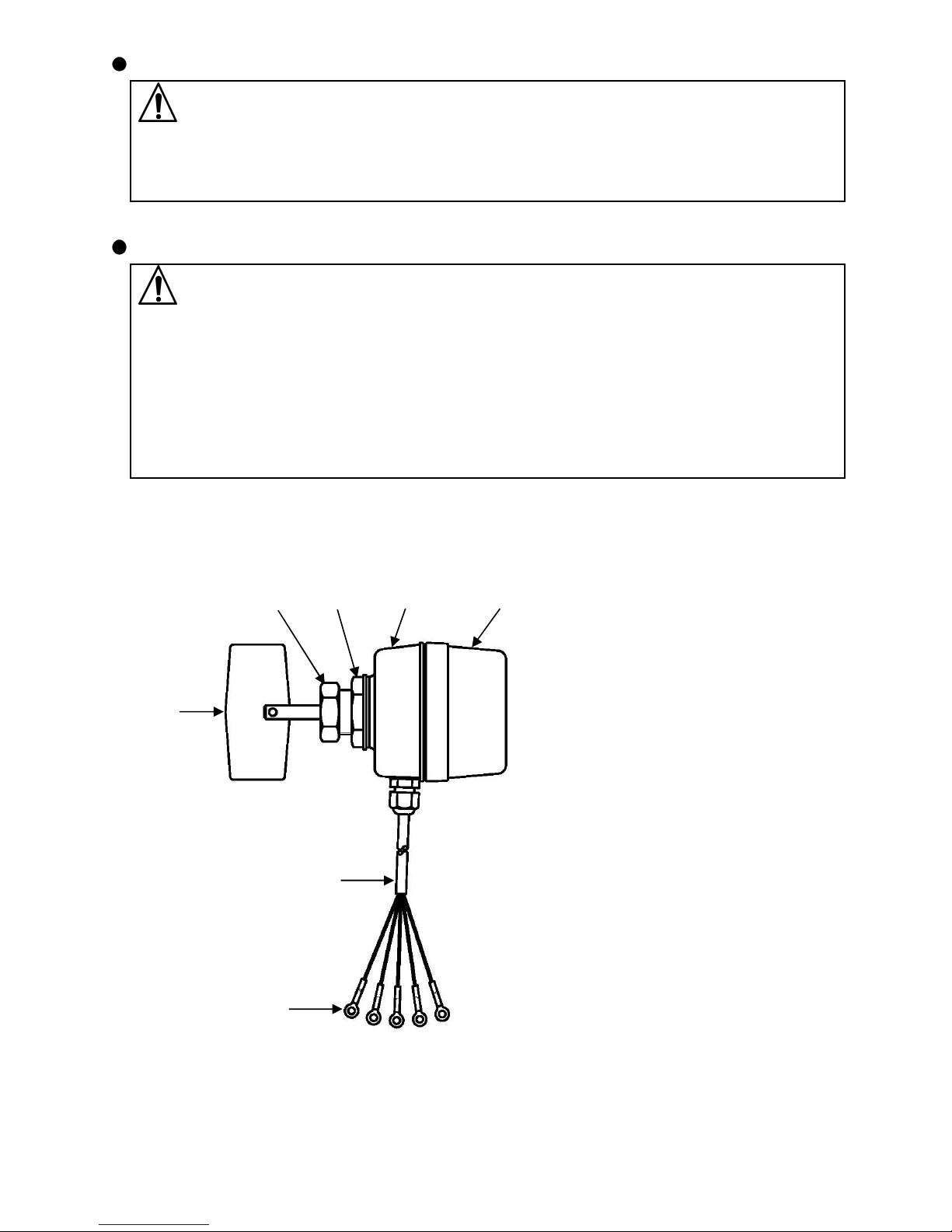
1. Name of sections
(1): Cover
(2): Case
(3): Main unit mounting nut
(4): Wing shaft fixing nut
(5): Detector wing
(6): Cabtyre cord
(7): Solderless terminal (ring type)
(Fig. 1.1)
(2) (1)
(5)
(3)
(4)
(6)
(7)
3
2. Mounting to hopper
2.1 Site selection and precautions
Ensure the mounting location corresponds to the following conditions, and follow
precautions below.
(1) A minimum of dust, and an absence of corrosive gases
(2) Few mechanical vibrations or shocks
(3) No exposure to direct sunlight, an ambient temperature of 0 to 55 (32 to 131 )
that does not change rapidly, and no icing
(4) Mount the instrument at the position where granule level actually changes.
(5) If the granule load is large, mount an adequate guard plate.
(6) Avoid mounting the instrument under the falling point of granules as well as near the
outlet.
(7) Mount the unit using the Main unit mounting nut.
When it is difficult to set or remove the wing in a hopper, use a flange (sold separately).
(8) Do not push and insert wing shaft too hard.
Insert it up to the point carefully, and then revolve it manually.
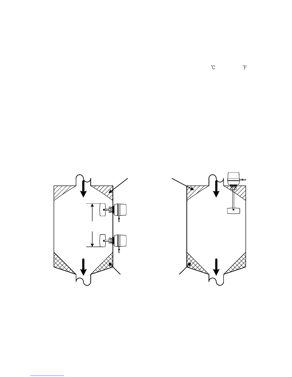
2.2 Mounting examples
[Good example]
• Horizontal mounting • Vertical mounting
(Fig.2.2-1) (Fig.2.2-2)
Empty room
Outlet
Inlet
Area where material tends
to accumulate
Outlet
Inlet
Level changing
area
4
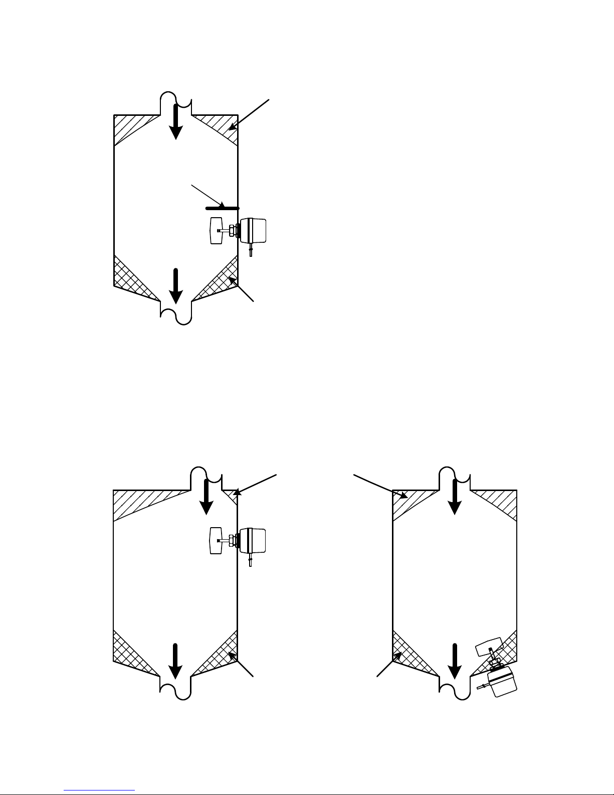
• For large loading
(Mount the guard plate when the granule loading is large.)
(Fig.2.2-3)
[Bad example]
• Under the inlet • Near the outlet
(Fig.2.2-4) (Fig.2.2-5)
Outlet
Inlet
Area where material tends to
accumulate
Empty room
Guard
plate
Empty room
Outlet
Inlet
Area where material tends
to accumulate
Outlet
Inlet

5
Nut and flange mounting
[Nut Mounting] [Flange Mounting]
(Fig.2.2-6) (Fig.2.2-7)
When using the LV-300 with a flange,
make a hole on the hopper which
enables the wing to enter.
2.3 Mounting of wing shaft
(Fig.2.3-1) (Fig.2.3-2) (Fig.2.3-3)
Insert the wing shaft up to the point where it can be inserted fully to the end position.
When it is difficult to insert the wing shaft to the end, revolve the wing shaft manually
clockwise or counterclockwise. See (Fig.2.3-2).
Tighten the wing shaft with the fixing nut. See (Fig.2.3-3).
Hopper
Main unit mounting nut
Flange
Hopper

6
Notice
Tighten the Wing shaft fixing nut and Main unit mounting nut with the specified torque
as shown below, otherwise the screws will be damaged.
(Table 2.3-1)
Appropriate torque Maximum torque
Wing shaft fixing nut 15 N•m Within 30 N•m
Main unit mounting nut 20 N•m Within 30 N•m
2.4 External dimensions (Scale: mm)
Detector length (L) Mounting direction
85mm
100mm
150mm
200mm Vertical mounting
250mm Vertical mounting
(Fig 2.4-1) Please specify the detector length when
ordering.
2.5 Hopper cutout (Scale: mm)
(Fig 2.5-1)
80
38
81
Detector length (L)
82
27+1
0
7
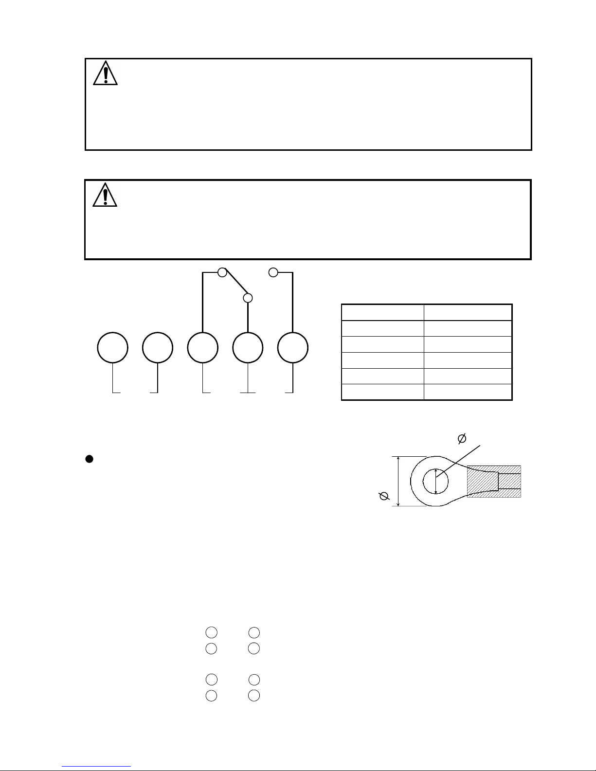
A C 1 2 3
3. Terminal arrangement
Warning
Turn the power supply to the instrument OFF before wiring and checking.
Working on or touching the terminal with the power switched ON may result in severe
injury or death due to electric shock.
Caution
This instrument has no built-in power switch and fuse.
It is recommended that power switch or fuse be set at the external circuit near this
instrument.
Solderless terminal for the cabtyre cord
Use a solderless terminal (ring type) in which
an M4 screw fits as shown in (Fig. 3-1).
4. Operation and action
4.1 Operation
When mounting to the hopper and wiring are completed, check the action as follows.
(1) Turn the power supply to this instrument ON.
(2) Detector wing starts to revolve with no load.
Between terminals 1and 2:Conductive
Between terminals 2and 3:Open
(3) When the load is added to the detector wing, the wing stops rotating.
Between terminals 1and 2: Open
Between terminals 2and 3:Conductive
Terminal code Lead wire color
A White
C Orange
1 Black
2 Brown
3 Green
8mm
4.3mm
(Fig. 3-1)
Power supply Load

8
SHINKO TECHNOS CO., LTD.
OVERSEAS DIVISION
Head Office:
URL:
E-mail:
2-5-1, Senbahigashi, Minoo, Osaka, Japan
http://www.shinko-technos.co.jp
overseas@shinko-technos.co.jp
Tel :
Fax:
+81-72-727-6100
+81-72-727-7006
4.2 Action explanation
When granule resistance is applied to the detector wing, the wing stops because the
granule resistance keeps it from revolving.
Micro switch between terminals 2and 3for internal load is conducted by the bar fixed
on the motor.
When the granule resistive load is given, power supply for the motor is disconnected
because the micro-switch for the motor operates.
When the granule level lowers, the detector wing is exposed, granule resistance does
not work and the detector wing starts to revolve with the motor.
Micro switch between terminals 1and 2for internal load is conducted at this time.
5. Specifications
Name : Level switch
Model name : LV-300
Torque : Detecting torque: 0.049N•m (0.5kg•cm) or more (fixed)
Number of revolution : 1min-1 (60Hz)
Supply voltage : 100V, 110V, 115V, 200V, 220/230V, 240V AC (Must be specified)
50/60Hz
Allowable voltage fluctuation range : 15% of the Supply voltage
Contact capacity : 3A 250V AC (resistive load)
Ambient temperature : 0 to 55
Detector length : 85, 100, 150, 200, 250mm (Must be specified)
Mounting : Nut screwing
(Mounting part thickness: Maximum 7mm)
Material
Case, Cover : Aluminum die-cast
Detector shaft : Stainless steel 8.0mm
Detector wing : Stainless steel t1.5mm
Lead wire : 5-core cabtyre cord, Length: 2m
Weight (Including cabtyre cord 2m)
Detector
length 85mm 100mm 150mm 200mm 250mm
Weight Approx. 645gApprox. 650gApprox. 670gApprox. 690gApprox. 710g
Color
Case, Cover : 7.5BG4/2.5 (Munsell value)
Drip-proof/Dust-proof structure : IP66 (excluding parts from the Main unit mounting nut to
detector wing)
Table of contents
Popular Switch manuals by other brands


Dynex
Dynex DX-HB4PT Quick setup guide

HP
HP Voltaire Grid Director 4036 IB 4X QDR 36P... Documentation roadmap

Analog Devices
Analog Devices ADG5412BF datasheet

ANTAIRA
ANTAIRA LMX-2602G-SFP Series Hardware manual

Edge-Core
Edge-Core ES4524M-PoE installation guide

Broadcast Tools
Broadcast Tools DAS 8.4 Plus Installation and operation manual