SHNING 3D Aoralscan 2 User manual
Aoralscan 2
IntraoralScan User Manual

Aoralscan 2 User Manual
SHNING 3D TECH Co.,Ltd Copyright 2019 All Rights Reserved
- 1 -
CATALOG
1. Read this First.............................................................................- 3 -
2. Safety Information .......................................................................- 8 -
3. Overview ...................................................................................- 20 -
4. Setting up the Scanner..............................................................- 29 -
4.1. Connecting the Scanner...................................................- 29 -
4.2. Disconnecting the Scanner..............................................- 31 -
4.3. Calibrating the Scanner....................................................- 31 -
5. Scanning Sreparation................................................................- 36 -
6. Clinical Case Quick Guide.........................................................- 40 -
6.1. Connection the Scanner...................................................- 40 -
6.2. Calibration........................................................................- 40 -
6.3. Create Order....................................................................- 40 -
6.4. Activate the scanner.........................................................- 41 -
6.5. Scan UpperJaw................................................................- 41 -
6.6. Scan LowerJaw................................................................- 43 -
6.7. Scan TotalJaw .................................................................- 43 -
6.8. View Result Data .............................................................- 45 -
6.8.1. View upperjaw/ lowerjaw...........................................- 45 -
6.8.2. View the occlusal effect.............................................- 45 -
6.9. Pre-Design.......................................................................- 46 -
6.10. View Data Storage Path...................................................- 46 -
6.11. Upload Order ...................................................................- 46 -
7. Using IntraoralScan...................................................................- 48 -
7.1. Introduction to IntraoralScan............................................- 48 -
7.2. Introduction to Calibration module ...................................- 48 -
7.2.1. Accuracy Checking....................................................- 49 -
7.2.2. Brightness Adjust ......................................................- 50 -
7.2.3. Calibration.................................................................- 50 -

Aoralscan 2 User Manual
SHNING 3D TECH Co.,Ltd Copyright 2019 All Rights Reserved
- 2 -
7.3. Introduction to Dental Order System................................- 51 -
7.3.1. Information ................................................................- 52 -
7.3.2. Order list....................................................................- 54 -
7.3.3. Setting.......................................................................- 57 -
7.3.4. Data storage..............................................................- 60 -
7.4. Navigating IntraoralScan Interface...................................- 61 -
7.5. Introduction to IntraoralScan Functions............................- 67 -
7.5.1. Scan technique..........................................................- 67 -
7.5.2. Loading project..........................................................- 69 -
7.5.3. Dental Order System.................................................- 69 -
7.5.4. Scan Upper/Lower Jaw.............................................- 69 -
7.5.5. Scan Upper Jaw/Lower Jaw Implant.........................- 73 -
7.5.6. Scan Metal Tooth......................................................- 77 -
7.5.7. Scan Total Jaw..........................................................- 78 -
7.5.8. Pre-design.................................................................- 81 -
7.5.9. Upload Order.............................................................- 88 -
8. Using Dental Cloud ...................................................................- 90 -
8.1. Introduction to Dental Cloud.............................................- 90 -
8.2. Register Account..............................................................- 90 -
8.3. Establish a Relationship Network.....................................- 92 -
8.4. Management Institution....................................................- 93 -
8.4.1. Add Member..............................................................- 93 -
8.4.2. Delete Member..........................................................- 93 -
8.4.3. Case Management....................................................- 93 -
8.5. Order Workflow................................................................- 94 -
9. Care and Maintenance..............................................................- 98 -
10. Hardware Specification ...........................................................- 111 -

Aoralscan 2 User Manual
SHNING 3D TECH Co.,Ltd Copyright 2019 All Rights Reserved
- 3 -
1. Read this First
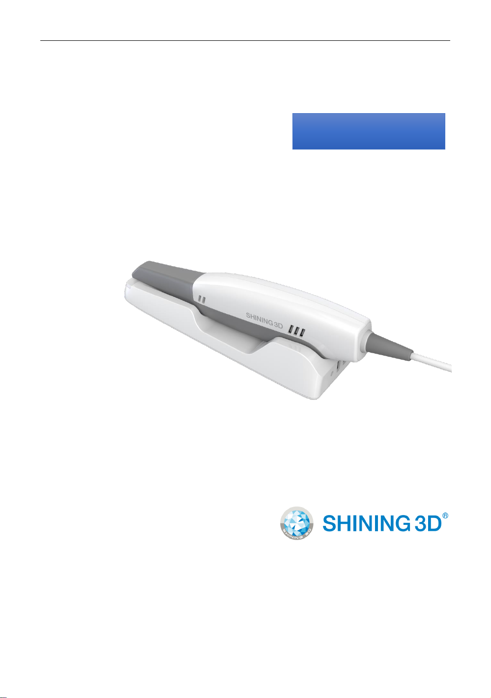
The Aoralscan 2 is an intraoral scanner that works with the supplied
software programs. With Aoralscan 2, you can perform oral scanning and
digitally acquire and save the 2D/3D color images of a patient’s teeth for
orthodontic, implant, and restoration use.
This User Manual provides important procedures and information on how
to operate the scanner and configure the IntraoralScan software correctly and
safely. Before attempting to operate the product, read this User Manual and
strictly observe all warnings and cautions. We suggest that you have easy
access to the User Manual whenever necessary. Pay extra attention to the
information from Safety information on chapter 2.
1.1. Copyright
Copyright ©2016 Shining3D Corporation. All rights reserved. No part of
this publication may be reproduced, transmitted, transcribed, stored in a
retrieval system or translated into any language or computer language, in any
form or by any means, electronic, mechanical, magnetic, optical, chemical,
manual or otherwise, without the prior written permission of Shining3D
Corporation.
All other logos, products, or company names mentioned in this User
Manual may be the registered trademarks or copyrights of their respective
companies, and are used for informational purposes only.
1.2. Disclaimer
Shining3D Corporation makes no representations or warranties, either
expressed or implied, with respect to the contents hereof and specifically
disclaims any warranties, merchantability or fitness for any particular purpose.
Further, Shining3D Corporation reserves the right to revise this publication
and to make changes from time to time in the contents hereof without
obligation of Shining3D Corporation to notify any person of such revision or
changes.
Aoralscan 2 User Manual
SHNING 3D TECH Co.,Ltd Copyright 2019 All Rights Reserved
- 4 -
Updates to hardware and/or software components are made regularly;
therefore, some of the instructions, illustrations, and specifications mentioned
in this User Manual may differ slightly from your particular situation. To obtain
the most updated and accurate information, visit en.shining3d.com for the
latest version of this User Manual.
1.3. Intended Use
An optical impression system for computer assisted design and
manufacturing (CAD/ CAM) is a device used to record the topographical
characteristics of teeth, dental impressions, or stone models by analog or
digital methods for use in the computer- assisted design and manufacturing of
dental restorative prosthetic devices. Such systems may consist of a camera,
scanner, or equivalent type of sensor and a computer with software.
WARNINGS
Do not use the scanner for purposes other than those intended and
expressly stated above.
This product is designed and intended for use by persons with
professions of dentistry and dental laboratory technology. The product can not
be operated by the patients themselves.
Do not misuse the scanner, and do not use or operate the software
programs incorrectly.
The clinical environments where the scanner and the software
programs can be used include dental clinics, dental hospitals, and dental
laboratories.
Only trained medical personnel may use the scanner and the supplied
software programs.
Installation, use, and operation of the scanner are subject to the law in
the jurisdictions in which it is used. Install, use, and operate the scanner only
in such ways that do not conflict with applicable laws or regulations, which
have the force of law. Use of the scanner for purposes other than those

Aoralscan 2 User Manual
SHNING 3D TECH Co.,Ltd Copyright 2019 All Rights Reserved
- 5 -
intended and expressly stated here, as well as incorrect use or operation, may
relieve us or our agents from all or some responsibilities for resultant
noncompliance, damage, or injury.
The users of this scanner and software are responsible for image
quality and diagnosis. They should ensure that the inspection data is being
used for the analysis and diagnosis only, and furthermore the data is sufficient
both spatially and temporally for the measurement approach being used.
The images acquired by the scanner must be interpreted by a qualified
medical professional. The software in no way interprets these images or
provides a medical diagnosis of the patient being examined.
1.4. Warnings
Before using the Aoralscan 2,read these warnings and Safety
information on chapter 2.
WARNINGS
Do not attempt to disassemble, repair, or modify the scanner and
software.
There are no user serviceable parts inside the scanner. Necessary
modifications must be made only by the manufacturer or its designated
agents.
Do not allow any liquid to get inside this scanner and its cradle. Water
and moisture may cause short-circuit to the electronic components and lead to
malfunctions.
Do not drop or apply shock/vibration to this scanner and its cradle.
Strong impacts may damage the components inside.
Do not cut, bend, modify, place heavy objects, or step on the cables.
Otherwise the external insulation may be damaged and result in short-
circuit or fire.
To avoid electrical shock, use only supplied power adapter and
connect it only to properly grounded wall outlets.
Aoralscan 2 User Manual
SHNING 3D TECH Co.,Ltd Copyright 2019 All Rights Reserved
- 6 -
The device should not be used adjacent to or stacked with other
equipment. If adjacent or stacked use is necessary, the device should be
observed to verify normal operation in the configuration in which it will be used.
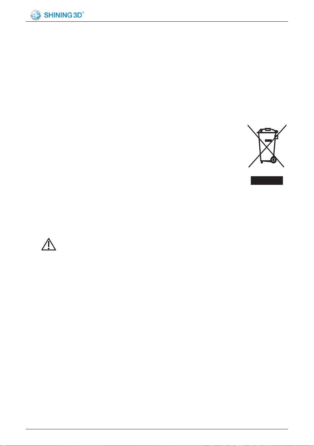
1.5. WEEE
Disposal of Waste Electrical and Electronic Equipment and by users
in private households in the European Union.
This symbol on the product or on the packaging indicates that this can not
be disposed of as household waste. You must dispose of your
waste equipment by handling it over to the applicable take-back
scheme for the recycling of electrical and electronic equipment
and/or battery. For more information about recycling of this
equipment, please contact your city office, the shop where you
purchased the equipment or your household waste disposal service. The
recycling of materials will help to conserve natural resources and ensure that it
is recycled in a manner that protects human health and environment.
1.6. Disposal
CAUTION
The scanner must be reprocessed prior to disposal in order to
prevent cross-contamination.
All electrical and electronic devices must be disposed of separately from
your other household waste in order to promote reuse, recycling and other
forms of recovery, to prevent any potential adverse effects of hazardous
substances on the environment and human health, and also to reduce the
amount of waste in landfill. This includes accessories such as power adapters,
power cords, etc. Do safely dispose of the device and its accessories in
accordance with applicable laws and regulations.
For specific information on disposal of your device and the packaging,
contact your local distributor or service provider.

Aoralscan 2 User Manual
SHNING 3D TECH Co.,Ltd Copyright 2019 All Rights Reserved
- 7 -
1.7. Typographics
Special notes, cautions, and warnings that appear throughout this User
Manual are designed to ensure that you perform specific tasks properly,
preventing unnecessary errors.
This icon marks NOTE(S); additional information for particular
situation
This icon marks CAUTION(S); improper actions or conditions that
may damage the product or injury, and consequently void your warranty
orservice contract or lose the patient data or system data.
This icon marks WARNING(S); the safety instructions that you must
precisely follow in order to avoid injury. Failure to observe can cause damages
to your product, or result in personal injuries, or even death.
1.8. Warranty
The warranty is void if unauthorized personnel perform service or
maintenance on the set of Aoralscan 2. To ensure correct product
performance and to obtain warranty service, contact technical support. For
more information, see the following.
1.9. Contact Information
Manufacturer
Shining 3D Tech Co.,Ltd
No.1398,Xiangbin Road,Wenyan,Xiaoshan,Hangzhou,Zhejiang,China
en.shining3d.com
Customer Support
Email:[email protected]

Aoralscan 2 User Manual
SHNING 3D TECH Co.,Ltd Copyright 2019 All Rights Reserved
- 8 -
2. Safety Information
2.1. Precautions
WARNING
Follow the procedures carefully and ensure that the
power/electrical/environmental requirements are satisfied. Failure to observe
the instructions or disregard the warnings may result in damages to the
product, personal injury, or even death of the user or the patient.
Observe the following precautions carefully.
Do not use the hardware and software for any application until you
have read, understood, and known all the safety information, safety
procedures, and emergency procedures contained in this chapter. Operating
the hardware and software without a proper awareness of safe use could lead
to fatal damage to the hardware or permanent data loss.
Ensure that the connection is performed correctly by following the
instructions given in Connecting the scanner on chapter 4.
Use only medical grade devices with the scanner in the patient
environment.
The hardware and software should only be used in a medical facility
under the supervision of trained personnel.
Only authorized service labs should perform maintenance. It is
expressly prohibited to open the scanner with tools.
The hardware and software have been fully adjusted and tested prior
to shipment from the factory. Unauthorized modifications will void your
warranty.
If the hardware or software is modified, appropriate inspection and
testing must be conducted to ensure continued safe use.
Use only supplied accessories and approved software with the
scanner in order to achieve the designed performance.
Do not use a power adapter other than the one supplied with the

Aoralscan 2 User Manual
SHNING 3D TECH Co.,Ltd Copyright 2019 All Rights Reserved
- 9 -
package.
Connecting the scanner to an unknown power adapter is very
dangerous and may lead to fire or explosion.
Using cables or accessories other than those specified for use with the
scanner may result in increased emissions or decreased immunity of the
device.
The supplied medical grade power adapter should only be connected
to a grounded power socket.
Do not connect USB peripherals with an extended USB cable.
Extended connection may cause unexpected usage fault.
Always handle the scanner with care and avoid hitting or scratching
the surfaces as it contains fragile components. Dropping the scanner on the
floor may cause permanent damage. If you accidentally drop the scanner, you
MUST dispose of the scanner tip immediately and do not use the same tip
again. The mirror in the tip might shatter into small pieces, and using it again
poses the highest risk of causing serious injury to the user and patient.
The scanner might heat up to above the normal body temperature, yet
this short- term exposure and contact with small areas will not pose a health or
safety hazard to the patient.
Never place any objects or load on the scanner and its cradle.
Pay close attention to the hygiene guidelines given in Pre-cleaning,
disinfection, and sterilization on chapter 9.
Do not dispose of this scanner as unsorted municipal waste. The
scanner must be collected separately and disposed of in accordance with the
local laws and regulations. For proper disposal of this scanner, contact your
local representative of Shining3D Corporation.
2.2. Legend of Labels and Symbols
The following symbols provide information on the product’s labels and
regulatory compliance.

Aoralscan 2 User Manual
SHNING 3D TECH Co.,Ltd Copyright 2019 All Rights Reserved
- 10 -
2.2.1. On the Device
Specification of scanner serial number
Serial number AOS-AH001K13 represents the No.001 device produced
on November 13. 2018.
AOS…represents the type of scanner which is the abbreviation of
Aoralscan2.
AH…represents the productive year, the letter A to I in
alphabetical order represent number 1 to 9 and the number 0 remains
the same.
001…represents the production serial number, the No.001 device.
K…represent the month, the letter A through L represent January
through December.
13…represent date by the number 0 through 31.
Symbol
Explanation
General warning –caution.
Indicates that the device complies with requirements for the BF
type applied part according to IEC 60601-1, providing protection
against electric shock.
Table 2-1 Labels and symbols on the device
On the carry box/package
Symbol
Explanation
General warning –caution.
Indicates that the device complies with requirements for the BF
type applied part according to IEC 60601-1, providing protection
against electric shock.
Indicates that the contents of the transport package are fragile
and therefore shall be handled with care.
Indicates that the transport package shall be kept dry.

Aoralscan 2 User Manual
SHNING 3D TECH Co.,Ltd Copyright 2019 All Rights Reserved
- 11 -
Indicates correct upright position of the transport package.
Indicates that the material shall be recycled.
Table 2-2 Labels and symbols on the carry box/package
2.3. Compliance
Anyone creating or changing a medical electrical system through a
combination with other devices in accordance with standard EN
60601-1-1:2001 based on 60601-1-1:2000 (specification for the safety of
medical electrical systems)/UL 60601-1 Part 1: first edition 2003 is responsible
for ensuring that the requirements of these standards are met to the full extent
in order to ensure the safety of patients, operators and the environment.
2.4. FCC Compliance Statement
This device complies with part 15 of the FCC Rules. Operation is subject
to the following two conditions: (1) This device may not cause harmful
interference, and (2) this device must accept any interference received,
including interference that may cause undesired operation.
2.5. Electrical Safety
Only trained medical personnel should operate this scanner. The product
complies with the following standards:
2.5.1. Electrical
IEC 60601-1-2:2014
IEC 60601-1:2015/A1:2012 (ed 3.1)
IEC 60601-1-6: 2013.Con Ed 3.1 Rev. October 29. 2013.
IEC 62366-1:2015
2.5.2. Classification
Type of protection against electric shock: Class II
The degree of protection against electric shock: Type BF

Aoralscan 2 User Manual
SHNING 3D TECH Co.,Ltd Copyright 2019 All Rights Reserved
- 12 -
The mode of operation: Continuous operation
Pollution degree 2
For maximum safety, observe the following guidelines strictly:
WARNINGS
Shock hazards exist if the power adapter is damaged or is not properly
grounded. Use only the supplied medical grade power adapter.
To avoid the risk of electric shock, connect the scanner only to
properly grounded wall outlets.
Only authorized service labs can make internal replacements of the
scanner and modify the software.
Do not use the scanner if its tip or cable is damaged. Contact technical
support for replacement of the damaged equipment (see Contact information
on chapter 1).
To avoid risk of electrical shock hazards, always inspect the scanner
and cable connections before use.
Check the cable housing before use. Do not use the scanner if the
housing is damaged or the cable is abraded.
All devices connected to the Aoralscan 2 shall comply with IEC
60601-1 and IEC 60950.
2.5.3. EMC Notice
Electromagnetic Emissions
Medical electrical equipment such as the Aoralscan 2 requires special
precautions regarding electromagnetic compatibility, and must be installed
and put into service according to the following electromagnetic tables.
The Aoralscan 2 is intended for use in the electromagnetic environment
specified below. The customer or user of the Aoralscan 2 should assure that it
is used in such an environment.
Aoralscan 2 User Manual
SHNING 3D TECH Co.,Ltd Copyright 2019 All Rights Reserved
- 13 -
Emission
measurement
Conformity
Electromagnetic environment - guidelines
RF emissions
CISPR 11
Gr 1
The Aoralscan 2 uses RF energy only for its
internal function. Therefore, its RF emissions
are very low and are not likely to cause any
interference in nearby electronic equipment.
RF emissions
CISPR 11
Class B
The Aoralscan 2 is suitable for use in all
establishments, including domestic
establishments and those directly
connected to the public low-voltage power
supply network that supplies buildings used
for domestic purposes.
Harmonic emissions
IEC 61000-3-2
Class D
Voltage fluctuations/
flicker according
IEC 61000-3-3
Complies
Table 2-3 Guidance and manufacturer’s declaration–electromagnetic emissions
Interference immunity
The Aoralscan 2 is intended for use in the electromagnetic environment
specified below. The customer or user of the Aoralscan 2 should assure that it
is used in such an environment.
Immunity test
IEC 60601 test
levels
Compliance level
Electromagnetic
environment–guidance
Electrostatic
discharge (ESD)
IEC 61000-4-2
±8 kV contact
±15 kV air
±8 kV contact
±15 kV air
Floors should be wood,
concrete or ceramic tile.
If floors are covered with
synthetic material, a
relative humidity of at
least 30% is
recommended.
Electrical fast
transient/burst
IEC 61000-4-4
±2 kV for power supply
lines
±1 kV for input/output
lines
±2 kV for power
supply lines
±1 kV for input/output
lines
Mains power quality should
be that of a typical
commercial or hospital
environment.
Surge
IEC 61000-4-5
±1 kV line(s)
to line(s)
±2 kV line(s)
to earth
±1 kV differential
mode
±2 kV common mode
Mains power quality should
be that of a typical
commercial or hospital
environment.
Immunity test
IEC 60601 test levels
Compliance level
Electromagnetic
environment–guidance
Aoralscan 2 User Manual
SHNING 3D TECH Co.,Ltd Copyright 2019 All Rights Reserved
- 14 -
Voltage dips,
short
interruptions and
voltage
variations on
power supply
input lines
IEC 61000-4-11
0% UT (100% dip in
UT) for 0.5/1 cyclea
40% UT (60% dip in
UT) for 5 cycles
70% UT (30% dip in
UT) for 25/30
cyclesa (for
0.5 sec)
0% UT (100% dip in
UT) for 250/
300 cyclesa
(for 0.5 sec)
0% UT (100% dip
in UT) for 0.5/1
cyclea
40% UT (60% dip
in UT) for 5 cycles
70% UT (30% dip
in UT) for 25/30
cyclesa (for
0.5 sec)
0% UT (100% dip
in UT) for 250/
300 cyclesa
(for 0.5 sec)
Mains power quality should
be that of a typical
commercial or hospital
environment. If the user of
the Aoralscan 2 requires
continued operation during
power mains interruptions,
it is recommended that the
Aoralscan 2 be powered
from an uninterruptible
power supply or a battery.
Power frequency
(50/60 Hz)
magnetic field
IEC 61000-4-8
30 A/m
30 A/m
Power frequency magnetic
fields should be at levels
characteristic of a typical
location in a typical
commercial or hospital
environment.
If image distortion occurs, it
may be necessary to
position the Aoralscan 2
further from sources of
power frequency magnetic
fields or to install magnetic
shielding. The power
frequency magnetic field
should be measured in the
intended installation
location to assure that it is
sufficiently low.
NOTE: UT is the a.c. mains voltage prior to application of the test level.
a For example, 10/12 means 10 cycles at 50 Hz or 12 cycles at 60 Hz.
Table 2-4 Guidance and manufacturer’s declaration–electromagnetic immunity
Aoralscan 2 User Manual
SHNING 3D TECH Co.,Ltd Copyright 2019 All Rights Reserved
- 15 -
Immunity test
IEC 60601 test levels
Compliance level
Electromagnetic
environment –guidance
Conducted RF
3 Vrms
150 kHz to
80 MHz outside ISM
bandsc
3 Vrms
Portable and mobile RF
communications equipment
should be used no closer
to
any
part of the Aoralscan,
including cables, than the
recommended separation
distance calculated from the
equation appliance to the
frequency of the transmitter.
Recommended
separation distance:
d = 1.2 √P
IEC 61000-4-6
Radiated RF
IEC 61000-4-3
6 Vrms
150 kHz to
80 MHz in
ISM bandsc
3 V/m
80 MHz to 2.7 GHz
6 Vrms
3 V/m
IEC 60601-1-2: 2007
d = 1.2 √P 80 MHz to 800
MHz d = 2.3 √P 800 MHz to
2.5 GHz IEC 60601-1-2:
2014
d=2.0 √P 80 MHz to 2.7
GHz
Where P is the
maximum output power
rating of the transmitter
in watts (W) according to
the transmitter
manufacturer and d is
the recommended
separation distance in
meters (m).
Field strengths from
fixed RF transmitters, as
determined by an
electromagnetic site
surveya, should be less
than the compliance
level in each frequency
rangeb.
Interference may occur in the
vicinity of equipment marked
with following symbol:
Table 2-4 Guidance and manufacturer’s declaration–electromagnetic immunity

Aoralscan 2 User Manual
SHNING 3D TECH Co.,Ltd Copyright 2019 All Rights Reserved
- 16 -

Aoralscan 2 User Manual
SHNING 3D TECH Co.,Ltd Copyright 2019 All Rights Reserved
- 17 -
Immunity test
IEC 60601 test levels
Compliance level
Electromagnetic
environment –guidance
NOTE 1: At 80 MHz and 800 MHz, the higher frequency range applies.
NOTE 2: These guidelines may not apply in all situations. Electromagnetic propagation is
affected by absorption and reflection from structures, objects and people.
a Field strengths from fixed transmitters, such as base stations for radio (cellular/ cordless)
telephones and land mobile radios, amateur radio, AM and FM radio broadcast and TV
broadcast cannot be predicted theoretically with accuracy. To assess the electromagnetic
environment due to fixed RF transmitters, an electromagnetic site survey should be
considered. If the measured field strength in the location in which the Aoralscan 2 is used
exceeds the applicable RF compliance level above, the Aoralscan 2 should be observed to
verify normal operation. If abnormal performance is observed, additional measures may be
necessary, such as reorienting or relocating the Aoralscan 2.
b Over the frequency range 150 kHz to 80 MHz, field strengths should be less than
3 V/m.
c The ISM (industrial, scientific and medical) bands between 150 kHz and 80 MHz are 6.765
MHz to 6.795 MHz; 13.553 MHz to 13.567 MHz; 26.957 MHz to 27.283
MHz; and 40.66 MHz to 40.70 MHz.
Table 2-4 Guidance and manufacturer’s declaration–electromagnetic immunity
To limit exposure to electromagnetic interference from nearby equipment
that can degrade image quality or launch warning messages, it is necessary to
position the Aoralscan 2 further from sources of electromagnetic interference
or install electromagnetic shielding to block unwanted interference. The
customer or the user of the Aoralscan 2 should operate the device under EMI
conditions that minimize power supply transients, mechanical interactions,
vibration, and thermal, optical, and ionizing radiation.

Aoralscan 2 User Manual
SHNING 3D TECH Co.,Ltd Copyright 2019 All Rights Reserved
- 18 -
Separation distances
The Aoralscan 2 is intended for use in the electromagnetic environment
in which radiated RF disturbances are controlled. The customer or the user of
the Aoralscan 2 can help prevent electromagnetic interference by maintaining
a minimum distance between portable and mobile RF communications
equipment (transmitters) and the Aoralscan 2 as recommended below,
according to the maximum output power of the communications equipment.
Rated
maximum
output
power
of
transmitter
(W)
Separation distance according to frequency of
transmitter
(
m)
IEC 60601-1-2 : 2007
IEC 60601-1-2 : 2014
150kHz
to
80
MHz
d = 1.2
√P
80 MHz to
800 MHz
d = 1.2 √P
800
MHz to
2.5
GHz
d =
2.3
√P
150kHz
to
80
MHz
d = 1.2
√P
80 MHz to
2.7 GHz
d = 2.0 √P
0.01
0.12
0.12
0.23
0.12
0.20
0.1
0.38
0.38
0.73
0.38
0.63
1
1.2
1.2
2.3
1.2
2.0
10
3.8
3.8
7.3
3.8
6.3
100
12
12
23
12
20
For transmitters rated a maximum output power not listed above, the
recommended separation distance d in meters (m) can be estimated using the
equation applicable to the frequency of the transmitter, where P is the maximum
output power rating of the transmitter in watts (W) according to the transmitter
manufacturer.
NOTE 1: At 80 MHz and 800 MHz, the separation distance for the higher frequency
range applies.
NOTE 2: These guidelines may not apply in all situations. Electromagnetic
propagation is affected by absorption and reflection from structures, objects
and people.
Table 2-5 Recommended separation distances between portable and mobile RF
communications equipment and the Aoralscan 2
The medical electrical equipment is suitable for the professional
healthcare environment per 60601-1-2:2014. It is suitable for use in physician
offices, clinics, hospitals, and other professional healthcare environments
except near HF surgical equipment and the RF shielded room of an ME

Aoralscan 2 User Manual
SHNING 3D TECH Co.,Ltd Copyright 2019 All Rights Reserved
- 19 -
system for magnetic resonance imaging or other environments where the
intensity of electromagnetic disturbances is high.
The clinical environments where the device can be used include physician
offices, clinics, hospitals, and clinical point-of-care for diagnosis of patients
except environments where the intensity of electromagnetic disturbances is
high.
WARNINGS
Portable RF communications equipment (including peripherals such
as antenna cables and external antennas) should be used no closer than 30
cm (12 inches) to any part of the Aoralscan 2, including cables specified by
the manufacturer. Otherwise, degradation of the performance of this
equipment could result.
If higher IMMUNITY TEST LEVELS than those specified in
IEC60601-1-2
Table 9 are used, the minimum separation distance may be lowered.
Lower minimum separation distances shall be calculated using the equation
specified in IEC60601-1-2 Chapter 8.10.
Table of contents
Popular Medical Equipment manuals by other brands


Simulaids
Simulaids SMART STAT BASIC 8002 Instruction and Care Manual

ADC
ADC Diagnostix 700 Series Use, care & maintenance

Steris
Steris VividImage MON-STE19-1MP Operation manual

SPIRIVA
SPIRIVA Respimat Instructions for use

Greiner Bio-One
Greiner Bio-One Vacuette QuickShield Instructions for use

Novametrix Medical Systems
Novametrix Medical Systems OXYPLETH 520A Service manual

mibeTec
mibeTec Bite Away Instructions for use

Acelity
Acelity V.A.C. Ulta Therapy System Safety Information And Instructions

LEM
LEM Aspimed 1.9 manual

Park House Healthcare
Park House Healthcare Endeavour Service manual

Graham Field
Graham Field LUMEX PATRIOT Homecare Bed Series user manual

sorin
sorin PLATINIUM SonR CRT-D 1811 Implant manual