Shocker XLS User manual
WARRANTY Warranty Support and Service for Shocker Paintball (SP) products is provided by factory trained service technicians at
SP Authorized Dealers.
SP warrants for one (1) year to initial retail purchaser that the Paintball Marker and Regulator components are free from defects in
materials and workmanship. The Valve Assembly and Solenoid are warranted for six (6) months. Disposable parts (Batteries,
O-Rings, Seals, etc.) are not warranted.
This warranty does not cover surface damages (scratches and nicks), misuse, improper disassembly and reassembly, attempts made
to drill holes or remove metal from external surfaces which could degrade the performance and reduce pressure safety factors of the
marker without written approval. Re-anodizing of any part of the marker voids any warranty claim. The only authorized lubricant for the
marker is GR33SE™ Lubricant. Use of any other lubricant could result in voiding your warranty. Paintball Markers are non-refundable.
This warranty is limited to repair or replacement of defective parts with the customer responsible for transporting the product to
and from the Shocker® XLS Authorized Dealer. Modication of any kind to the trigger assembly may result in serious injury, any
modications made to this system void all warranty obligations.This warranty is effective only if the customer registers their
marker online at www.shockerpaintball.com/support in our RMA system within 30 days of original purchase.
The warranty is non-transferable.
FIG. 2
Shocker® and Freak® are registered trademarks owned by G.I. Sportz Inc. and used under license by Philadelphia Americans, LLC.
QUICK START
GUIDE [v1.0]
BOLT MAINTENANCE
MARKER SETUP
WARRANTY
WARNING THIS IS NOT A TOY. MISUSE OF THE SHOCKER XLS MAY RESULT IN SERIOUS INJURY OR DEATH. EYE PROTECTION
DESIGNED FOR PAINTBALL USE MUST BE WORN BY THE USER AND ANY PERSON WITHIN RANGE OF THE SHOCKER® XLS.
SHOCKER PAINTBALL (SP) RECOMMENDS THAT THE SHOCKER ® XLS ONLY BE SOLD TO PERSONS 18 AND OLDER.
THOROUGHLY READ THE SHOCKER® XLS QUICK START GUIDE BEFORE OPERATING.
WWW.SHOCKERPAINTBALL.COM
SHK208
SHK256
SHK110
SHK304
SHK123
CLP003
SHK103
SPR016
SHK205BUM004
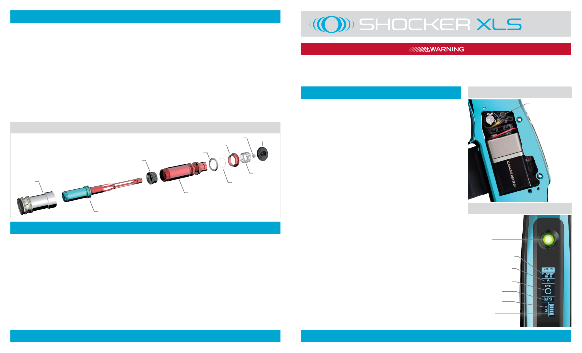
POWER
PROGRAMMING
LOCK
MODE & BPS CAP
PROGRAMMING
LOCK
VISION STATUS
LIVE ROF
SOFTWARE
VERSION
BATTERY
LEVEL
01 BATTERY
02 POWER
06 BOLT DISASSEMBLY
VALVE AND BOLT DISASSEMBLY/ MAINTENANCE When cleaning or maintenance is necessary, unload and degas the marker. If the
valve release button is pressed while the Shocker® XLS is still pressurized the bolt system will eject approximately 1/2 inch and degas safely.
*NOTE*– It is strongly recommended that the Shocker® XLS be degassed before pressing the valve release button. Pressing the valve
release button while the marker is pressurized will un-seat the front most o-ring on the main chamber [SHK208] [FIG. 06]. Simply
reinstall this o-ring prior to reassembly. To access the bolt system, press the valve release button at the rear of the body. Pull the valve
assembly out of the body by its tail cover.
Unscrew the main chamber [SHK304] from the ring can [SHK208] and remove the bolt. Remove the chamber guide [SHK110] from
the main ring chamber as well.
Clean all parts and the interior of the body with a soft cloth and inspect all O-rings for tears or other damage – replace if necessary.
Lightly lubricate all O-rings with GR33SE™ marker lubricant (DO NOT USE OIL) and reassemble in reverse order.
Take care not to cross-thread the bolt pieces while re-assembling. Gently slide the valve assembly into the Shocker® XLS and press
in on the Tail Cover until it latches in place. If the latch does not engage; check for debris in the latch and conrm the bolt system is
correctly assembled and its components snuggly tightened.
BATTERY A 9-volt battery powers the electronic components in the Shocker
XLS. For optimal performance, alkaline batteries (ANSI type 1604A) should be
used. Lower cost “heavy duty” zinc/carbon batteries should be avoided. Most 9v
rechargeable batteries will work with the Shocker® XLS, however their charge
levels may display inaccurately due to amperage limitations of the battery.
To install or replace the battery in the Shocker® XLS, place the marker on a at
surface with the feed tube on your left hand side. Remove the three grip screws
using a 5/64-inch allen wrench. Grasp the battery lead wires and connector,
and snap the connector onto the battery. Wrap the battery lead wires around
the connector once, this will secure the wires and prevent them from being
pinched when placing the battery into the frame. The battery should be installed
with the connector pointing toward the top of the grip frame. [FIG. 01]
Because the Shocker® XLS circuit board draws a very small amount of current
from the battery even when it is turned off, it is best to remove the battery if the
marker is going to be stored for a few weeks or more.
POWER BUTTON Turn on the Shocker® XLS by pressing and holding the power
button for a full second. As soon as the Shocker® XLS is on, it is live and ready
to re. Press and hold the power button to turn off the Shocker® XLS. [FIG. 02]
VISION ON/OFF Vision mode is active by default upon start up of the Shocker®
XLS. The power button ashing or glowing green will indicate that vision mode
is active, and an open or lled circle under “EYE” will be indicated on the OLED
screen. To disengage vision mode, press the power button for one second, the
power button will ash red and the OLED screen will indicate “OFF” in the vision
section.
PROGRAMMING LOCK The Shocker® XLS is equipped with a programming
lock feature. When the Shocker® XLS is locked, the electronic settings that
impact ring modes, rate of re and velocity may not be changed. Because the
lock button cannot be accessed without tools, the Shocker XLS complies with all
major tournament and scenario rules as well as common paintball eld practices.
The OLED screen will display the programming lock status. A padlock symbol
appears closed while the marker is locked, and appears open while it is unlocked.
To lock or unlock the Shocker® XLS, access the board through the grips (see
Battery Installation). With the marker turned on, momentarily press the lock
button [FIG. 01] to toggle locked or unlocked status.

TRIGGER ADJUSTMENT The Shocker® XLS has four adjustments of
trigger customization. All set screws are adjusted with a 1/16” allen key.
Magnetic Tension- This set screw is located at the top of the trigger; it is
the set screw closest to the trigger guard. Adjusting this set screw will alter the
weight of the trigger pull. [FIG. 03 A]
Pre-Travel - This set screw is located at the top of the trigger behind the
magnetic tension set screw. Adjusting this set screw will alter the forward
travel of the trigger pull. [FIG. 03 B]
Firing Point – This adjustment is accessed through the hole in the trigger
face. Adjusting this set screw will alter the point where the trigger activates
the ring switch on the control board. [FIG. 03 C]
Post-Travel- This adjustment is accessed by placing the allen wrench at
a slight angle from the left hand side of the marker. Adjusting this set screw
will alter the rearward travel length of the trigger pull. [FIG. 03 D]
BARREL Assemble and install the included barrel – make sure The Freak®
insert is in the barrel back. Put the supplied barrel blocker over the end of the
barrel and secure it around the Shocker® XLS body.
BARREL BLOCKER A barrel blocking device must be used any time the Shocker®
XLS (or any other paintball marker) is connected to an air source and is in an area
where people are not protected by paintball goggles or paintball eld netting.
It is important to make sure that the barrel blocker is securely in place when it is
used. To put the barrel blocker on the Shocker® XLS, slide the bag part of the blocker
over the end of the barrel and loop the cords over the back of the marker. Adjust the
cord lock so that the barrel blocker is held snugly in place and cannot slip free.
LOADER Insert your loader into the feedneck and make sure it is secure. Due
to the high rates of re that Shocker® XLS can achieve, we recommend the use
of a modern high-performance loader.
AIR SOURCE (HPA) The Shocker® XLS is designed to be powered by a high-
pressure compressed air (HPA) system only. Use of carbon dioxide (CO2) to
power the Shocker® XLS is likely to cause damage to sensitive internal seals
and will result in a voided warranty.HPA systems with a 3000psi or 4500psi
capacity can be utilized on the Shocker® XLS. HPA systems with output
pressures between 400psi and 850psi can be used with the Shocker XLS. An
output pressure of 800-850psi is recommended for maximum consistency at
high rates of re (15bps+) HPA systems are shipped empty, and must be lled
by properly trained persons. Once lled, the HPA system is attached to the
Shocker XLS by screwing it in to the bottom-line ASA. [FIG. 05]
VELOCITY ADJUSTMENT Velocity must be tested at the start of each
paintball session. Fill the loader with paintballs and turn it on. While wearing
ASTM compliant paintball goggles in an area where all bystanders are protected,
remove the barrel blocker and re over a chronograph to measure the velocity.
Using a 5/32” hex key, turn velocity up (clockwise) or down (counterclockwise).
After each adjustment take 2 or three shots to allow pressure to stabilize, then
test velocity again. For safety, and to avoid internal damage, never adjust the
Shocker® XLS to re at greater than 300 feet per second. [FIG. 04]
ASA The Shocker® XLS is equipped with a bottom-line style air source adapter
(ASA) [FIG. 05]. Before screwing an HPA system into the ASA, make sure the
ASA is turned off by loosening the knob located on the front of the ASA. After
screwing in the HPA system, air is released into the marker by tightening the
knob on the front of the ASA. When turning the ASA off, a small amount of air
will vent from the ASA with a brief hissing sound, this is normal. Turning off
the ASA does not completely depressurize the Shocker® XLS and may leave
enough gas inside the marker to re 2 or more shots. Discharge this air by ring
the marker without paintballs in a safe and secure area.
PROGRAMMING Unload and de-gas the Shocker® XLS, then turn it on while holding the trigger down. Release the trigger when the Shocker®
XLS has booted into its settings menu. Tap the trigger to scroll through the available settings. Separate settings are recorded for each ring
mode. For example, the Rate of Fire Cap (ROF cap) in a league requiring Capped Semi-Automatic mode may be different from the ROF cap in a
league using PSP mode. When the Firing Mode of the Shocker® XLS is changed, the ROF cap changes with it. Only the settings used with the
currently selected ring mode are displayed in the Settings Menu. Hold the trigger down for two seconds to select a setting for adjustment.
Tap the trigger to scroll through the values available for the setting, then hold the trigger down for a second to select. After adjusting settings,
press and hold the power button to save the changes and turn off the Shocker® XLS. The Shocker® XLS may be returned to its factory default
settings by holding the trigger down for 5 seconds while in programming mode. The screen will ash when a factory reset is done.
SETTINGS
BURST COUNT – The number of shots red per trigger pull in BURST Firing Mode.
RAMP START – How quickly RAMP mode ramps up the rate of re compared to the rate of trigger pulls.
RAMP PRCNT – Ramp Percentage – How much faster the RAMP mode should make the rate of re compared to the rate of
trigger pulls when it is fully engaged.
TRGGR DBNCE – Trigger Debounce - Adjusts the length of time the XLS processor must see a signal from the trigger switch needed to qualify
as a trigger pull. Setting Trigger Debounce too low may result in more than one shot per player’s pull of the trigger in semi-automatic modes.
MECH DBNCE – Mechanical Debounce - Adjusts how the XLS processor filters out trigger signals caused by mechanical vibration.
Setting Mechanical Debounce too low may result in more than one shot per player’s pull of the trigger in semi-automatic modes.
FSDO ADJUST – First Shot Drop Off (FSDO) Adjust – When the Shocker® XLS sits for several seconds between shots, the bolt may
require a higher dwell time to break friction and re at the full velocity. FSDO Adjust sets this dwell in milliseconds.
FSDO TIMER – First Shot Drop Off Timer – The amount of time in seconds the Shocker® XLS must sit idle before a shot is
considered the “rst shot” in need of higher dwell time to break friction.
AUTO OFF – The amount of time (minutes) that the Shocker® XLS can be unused before it turns itself off to conserve battery charge.
TIMER ENABLE – Enables or disables the game timer.
TIMER ADJUST – Sets the length of the game timer in minutes.
OLED (SCREEN MODES)
MODE – The currently selected ring mode and its Rate of Fire Cap (ROF cap) are shown near the top of the OLED display.
VISION – The status of the Vision anti-chop system is shown as a paintball in the middle of the display. A hollow paintball indicates
that the breech is empty. Solid indicates that it is full and ready to re. If a problem is detected “EYE FAULT” will be displayed. Vision
may be manually turned on or off by pressing the power button for one second. The power button will blink and the display will read
“EYEOFF” with an X in place of the paintball when Vision is off. When Vision is off or faulted the power button will be red and the
Shocker® XLS pause slightly between shots to allow more time for the ball to settle in place.
BATTERY – Estimated battery charge level is indicated in the lower right of the display. Accuracy may vary between battery brands,
especially rechargeable.
LIVE ROF – The highest rate of re achieved during the last few seconds is shown below the middle of the display.
FIRMWARE VERSION – When the game timer is off, the rmware version is shown in the lower left corner of the display. Shocker®
XLS rmware updates may be needed to comply with laws restricting ring modes in different countries, changes in league modes or
to change languages used in the OLED display. Firmware installation instructions and software are available at ShockerPaintball.com.
GAME TIMER – When enabled, the game timer is displayed in the bottom left of the display. The timer starts counting down when the
rst shot is red. Turning the Shocker® XLS off and back on again will reset the timer.
FIRING MODES
SEMI – Semi-automatic – One shot per trigger pull. This is the only mode not limited by the rate of re (ROF) Cap.
C SEMI – Capped Semi-automatic – Same as Semi, but will not re faster than the ROF Cap.
NXL– National X-Ball League – One shot per trigger pull. When the trigger is pulled faster than 5 times per second, additional shots
are red with each trigger pull, up to the ROF Cap rate. This will be updated if league changes its ring mode restrictions.
PSP – Paintball Sports Promotions – Fires like Semi until three fast trigger pulls then res repeatedly at ROF Cap rate as long as the
trigger is pulled and released. If one second goes by without a trigger pull or release, the marker reverts to ring one shot per trigger pull.
MILL – Millennium League – One shot per trigger pull. When the trigger is pulled faster than 5 times per second, additional shots are
red with each trigger pull, up to the ROF Cap rate.
RESP – Auto Response – Fires on both the pull and release of the trigger.
BURST – Multi-shot burst - Fires a burst of shots at the ROF Cap rate when the trigger is pulled and held. Stops ring if the trigger is
released before the burst is complete.
AUTO – Safety Full Automatic – Fires repeatedly at the ROF Cap rate when the trigger is pulled, released, then quickly pulled and held.
SELECT – Select Fire – Allows the marker to be switched between SEMI, PSP1 and NXL modes by tapping the power button, even if
the Tournament Lock is locked. When Select Fire is in use, the OLED Displays SELECT SEMI, SELECT PSP1 or SELECT NXL, depending
on which mode is in use.
RAMP – Ramping – Begins ring one shot per trigger pull, begins ring progressively at a pace faster the trigger, as the trigger is pulled faster.
3 QUICKSTART RIGHT INSIDE
ELECTRONIC ADJUSTMENTS MECHANICAL ADJUSTMENTS
FIG. 2
FIG. 2
FIG. 2
C
D
A
B
+
–
AIR OFF
(LOOSEN)
AIR ON
(TIGHTEN)
03 TRIGGER ADJUSTMENTS
04 VELOCITY ADJUSTMENT
05 ASA


