BOOST BOLT
ASSEMBLY AND MAINTENANCE
BOLT MAINTENANCE FREQUENCY
It is recommended that the NT11 Boost bolt be cleaned and re-lubed after each day of use. In
addition to performing standard maintenance, it is recommended that all o-rings on the NT11
Boost bolt be replaced after 80,000 cycles (40 cases of paint). There are seven static O-rings in
the Boost Bolt Kit (5x 020, 2x 011) that should be replaced if the bolt kit is removed and installed
frequently. During standard maintenance check these O-rings for damage, but for regular use
these O-rings rarely need to be replaced.
After 150,000 shots (or 75 cases of paint) it is a good idea to remove all of the O-rings in the
Boost Bolt Kit, and rinse bolt parts in warm water. Once the parts are dry, assemble the Boost
Bolt Kit using all new O-rings. Apply a small amount of DYE Slick Lube™ to all parts. At this time,
it is important to check the spool bumpers as well as the Bolt Flow Insert for excessive wear.
COMPLETE BOLT DISASSEMBLY
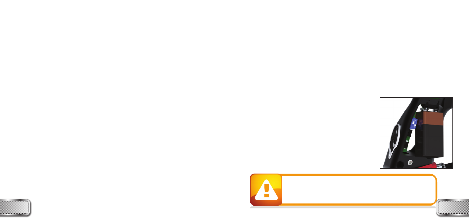
To separate all Boost bolt parts begin by removing the Boost Bolt Kit with a 1/4” Allen wrench.
Only one and a half counterclockwise rotations is required so that the bolt kit can be pulled out.
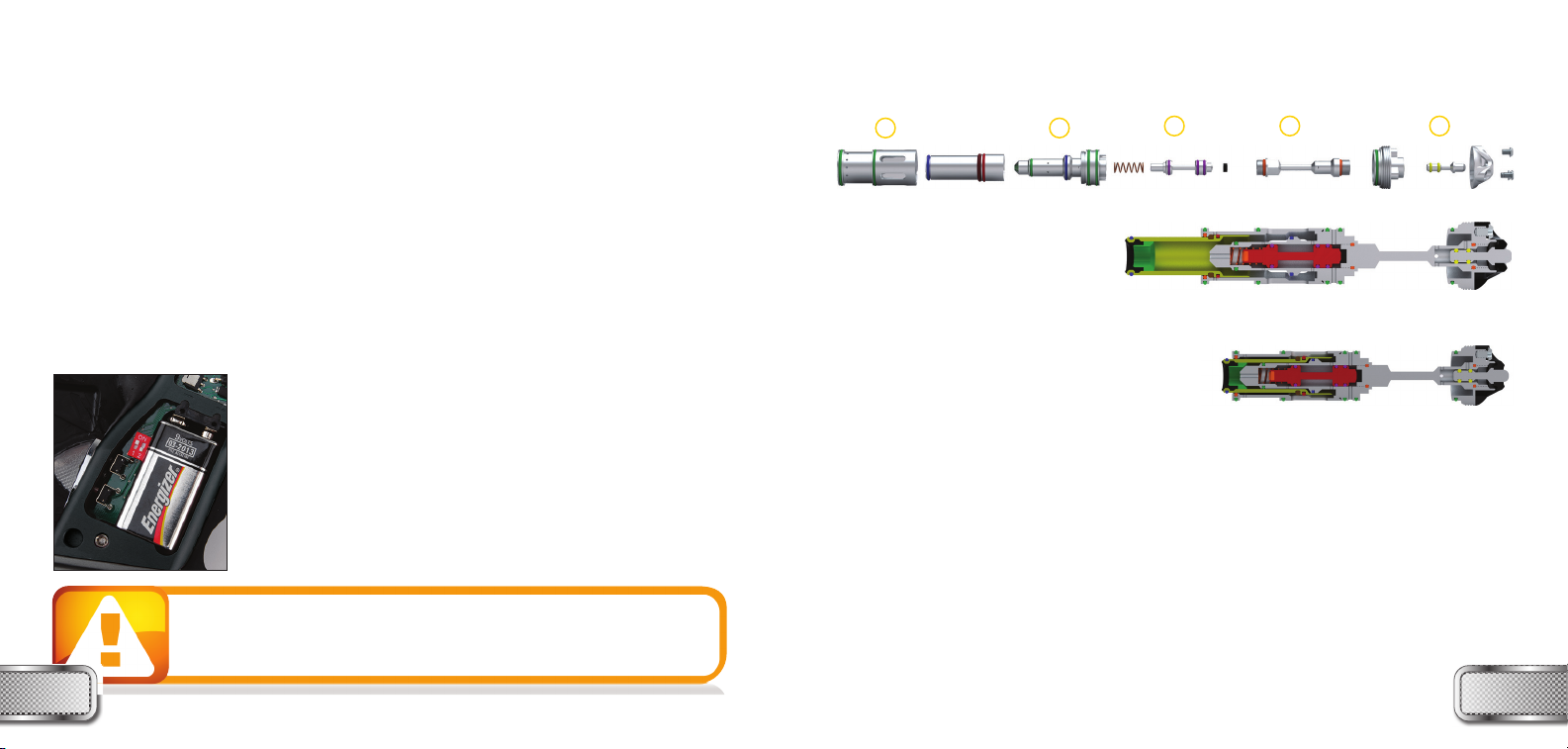
• Remove the 014 Bolt tip O-ring with a pick supplied on the DYE Multi-Tool
• Unscrew the Cylinder from the Plunger by rotating it counter-clockwise and set aside
• Pull the bolt off the plunger
• Remove the Bolt Flow Insert, use a 1/4” Allen wrench or dowel to push the
Bolt Flow Insert through the Bolt Soft Tip towards the back of the bolt
• Once the Bolt Flow Insert is removed, pull the soft bolt tip out the front of the bolt
• Separate the Plunger and Spacer Rod by using a 7/16” wrench One is included in the DYE
Multi-Tool. Secure the Spacer Rod with the wrench, and unscrew the Plunger by hand, rotating
he Plunger counter-clockwise. If the threads are locked together, a 5/64” Allen wrench can
be inserted into the Solenoid air transfer holes on the Plunger, to get a better grip.
• The Spool can be removed by pulling it from the Plunger with a pair of needle-nose pliers, or
by inserting a long Allen wrench or dowel into the front of the Plunger. Simply shake or
gently knock the Plunger against the table to remove the Spool Spring.
BOOST BOLT
ASSEMBLY AND MAINTENANCE
• Remove the Backcap from the Spacer rod, use a 7/16” wrench to hold the Spacer Rod and
insert a 1/4” Allen wrench into the Backcap. Rotate the Spacer Rod counter-clockwise until
released from the Backcap
• The Bleed Button can be removed from the Spacer Rod with a pair of needle-nose pliers
• To separate the Backcap and Backcap Cover use a 3/32” Allen wrench, and unscrew the three
retaining screws. This level of disassembly is not needed for any maintenance.
• Screw the Spacer Rod into the Backcap using a 7/16” wrench to tighten snugly. Take care not
to over-tighten the two pieces together. Excessive force may twist, warp, and ultimately break
the Spacer Rod.
• Insert the Bleed Button return Spring and the Bleed Button into the Spacer Rod
• Slide the Back Cap Cover over the Back Cap and secure using a 3/32” allen wrench to fasten
the three screws around the outside.
• Insert the Spool Spring and Spool into the Plunger. Make sure that the Spool is facing the
correct direction (see page 19).
• Screw the Spacer Rod into the Plunger. It is only necessary to hand tighten the Spacer Rod
and Plunger. Applying lube to the 011 o-ring can reduce sticking.
• Insert the Bolt Soft Tip into the front of the Bolt.
• Insert the Bolt Flow Insert from the back of the bolt, with the larger diameter of the insert
facing rearward.
• Push the bolt onto the Plunger and screw on the Cylinder only hand tight. Replace the 014 Bolt
tip O-ring, and re-install the Boost Bolt as described on page 18.
WWW.DYEPAINTBALL.COM 1716 WWW.DYEPAINTBALL.COM