Shopsmith 11" User manual

Shopsmith, Inc.
11” Bandsaw
WARNING
• Read the Safety section and complete the
Setup procedures before operating the
Shopsmith 11” Bandsaw.
• Mount the Bandsaw on Shopsmith equip-
ment only.
• Use only Shopsmith parts and accessories on
your Bandsaw. Mounting the Bandsaw on
non-Shopsmith machinery or using non-
Shopsmith parts could create a hazardous
condition and will void your warranty.
Table of Contents
Introduction .............................................. 2
Safety ......................................................... 2
Terms to Know......................................... 5
Specifications............................................ 7
Electrical Requirements.......................... 7
Assembly .................................................. 8
Alignment ............................................... 11
Operations .............................................. 21
Bandsaw Speeds .................................... 22
Making a Cut .......................................... 22
Helpful Cutting Hints ........................... 24
Ripping & Crosscutting ........................ 25
Resawing................................................. 26
Making Bevel Cuts ................................ 26
Cutting Round Stock ............................. 27
Making Duplicate Cuts......................... 27
Compound Cutting ............................... 27
Cutting Particle Board,
Plastics & Metals ................................. 28
Offsetting the Blade............................... 29
Removing & Mounting Blades ............ 30
Maintenance ........................................... 33
Sharpening Blades ................................. 33
Resurfacing Guide Blocks .................... 34
Cleaning the Bandsaw .......................... 35
Lubricating Bandsaw ............................ 35
Storing the Bandsaw.............................. 36
Bandsaw Tires ........................................ 36
Waxing the Bandsaw............................. 37
Maintenance Schedule .......................... 38
Troubleshooting .................................... 38
Correcting Blade Lead .......................... 38
Troubleshooting Guide ........................ 39

SHOPSMITH 11” BANDSAW 555943
Page 2
Introduction
The Shopsmith Bandsaw gives you the ability
to crosscut, rip, resaw, pad saw, plus cut
bevels and round stock. The Bandsaw is also
useful for compound cutting, creating shapes
that appear to be carved. You can cut both
natural and man-made woods, most plastics
and some metals with the Bandsaw. Also,
whentheShopsmithSpeedReducer (optional)
is attached to the Shopsmith Mark V, you can
properly cut an even wider range of materials
(the Speed Reducer cannot be used with the
Power Station or Power Stand).
The Shopsmith 11" Bandsaw will accomplish
many woodworking operations that are diffi-
cult or impossible with other tools. Basically,
the Bandsaw blade is an endless loop (or
“band”) of saw teeth revolving on two large
wheels. The thin, flexible blades allow you to
cut curves and other irregular shapes. The
fast cutting action makes it easy to resaw
thicker boards into thinner ones. But these are
just two of the operations your Bandsaw will
do. As you work with this machine, you’ll
find it has many other features that add ease
and versatility to your woodworking.
Safety
The Shopsmith Bandsaw has many built-in
safety features. But the effectiveness of these
features depends on you. Power tool safety is
no more than good common sense. To protect
yourself from injury: READ, UNDERSTAND
AND FOLLOW ALL the information in this
manual. Themeanings of WARNINGS, CAU-
TIONS and NOTES are:
WARNING
• A WARNING is given when failure to follow
the directions could result in injury or loss of
limb or life.
CAUTION
A CAUTION is given when failure to follow
the direction could result in temporary or
permanent damage to the equipment.
NOTE
A NOTE is used to highlight an important
procedure, practice or condition.
General Safety Rules for All
Power Tools
WARNING
• Read, understand and follow this instruction
manual and the manual for whichever power
source(s) you will be using (Mark V, Power
Station or Power Stand).
• Ground all tools (unless double-insulated).
• Keep guards in place and in working order.
Most injuries occur on unguarded power
tools.
• Remove adjusting keys and wrenches before
attempting to operate any tool.
• Do not wear loose clothing, ties, gloves or
jewelry. Roll sleeves up above your elbows,
wear nonslip footwear, and tuck long hair
under a hat.
• Do not operate power tools if you are fatigued
or taking medication or are under the influ-
ence of alcohol or drugs.
• Do not use power tools in damp, wet or
explosive atmospheres.
• Keep work areas well-lit, clean and free from
clutter.

Page 3
SHOPSMITH 11” BANDSAW 555943
• Do not force the tool. It will do the job better
and safer at the rate for which it was de-
signed.
• Do not use a tool or accessory to do a job for
which it was not designed.
• Repair or replace damaged parts before fur-
ther use. If a strange noise or vibrations
develops, turn off and unplug the machine.
Correct the problem.
• Use clamps, fixtures and other devices to hold
workpieces when practical.
• Do not overreach. Keep proper footing and
balance at all times.
• Do not try to stop the tool by grabbing the
workpiece or any part of the tool. Turn off
the tool and let it come to a complete stop by
itself.
• Do not leave the tool running unattended.
• To discontinue operations, turn the power
off. Don’t leave the tool until it comes to a
complete stop.
• Avoid unintentional starting. Make sure the
switch is in the “Off” position before plugging
in or unplugging the tool.
• Keep tools sharp, clean and maintained ac-
cording to the instruction manual.
• Make your workshop childproof. Unplug
tools, use padlocks and master switches, and
remove starter keys.
• Keep children away. All visitors should stay
a safe distance from power tools and wear eye
and ear protection.
Eye Protection
• Always wear eye protection when you use
power tools. Use goggles, safety glasses or a
face shield to protect your eyes.
• Goggles completely surround and protect
your eyes. Many goggles will also fit over
regular glasses. Be sure your goggles fit
closely, but comfortably.
• Safety glasses don’t fog as easily as goggles
and can be worn all the time. Regular glasses
normally have only impact-resistant lenses.
They are not safety glasses.
• A face shield protects your entire face, not
just your eyes.
Safety Rules for the Bandsaw
WARNING
• Mount the Bandsaw only on the Shopsmith
Mark V, Power Station or Power Stand.
Mounting the Bandsaw on non-Shopsmith
machinery or using non-Shopsmith machin-
ery or using non-Shopsmith parts could cre-
ate a hazardous condition and will void your
warranty.
• Use only Shopsmith parts and accessories on
your Bandsaw.
• Do not remove stock or scraps until the blade
has stopped.
• Maintain proper adjustment of blade ten-
sion, blade guides and bearings.
• Keep the upper guide adjusted to a maximum
of 1/4" above the stock.
• Never reach close to the blade or under the
table while the tool is running.
• Hold stock firmly against the table.

SHOPSMITH 11” BANDSAW 555943
Page 4
• Never reach close to the blade or under the
table while the tool is running.
• Hold stock firmly against the table.
• Never attempt a turn tighter than the blade
will allow; otherwise, the blade might break.
• Use a push stick to finish a resawing or rip-
ping cut.
• Keep your hands, fingers and other parts of
your body out of the danger zone.
• Support long stock with a roller stand.
• Hold round stock in a V-block.
• Never cut extremely small stock. Cut small
components from larger stock.
• If the blade breaks, turn off the machine and
stand away until it stops.
• Whenever you mount and operate the
Bandsaw on the Mark V, secure the acces-
sory mount lock, headstock lock and the
Bandsaw mounting tubes. Do not exceed the
speed setting “D”.
• Never turn on the tool with stock pressed
against the blade.
• If you hear a ticking sound or other unusual
noise, stop the Bandsaw immediately. A tick-
ing sound often indicates a damaged blade.
• Never reach close to the blade or under the
table to make adjustments, clear away chips
or for any reason whatsoever while the ma-
chine is running. Turn off the machine and
let the blade come to a complete stop.
• Keep your hands outside the DANGER
ZONE-which is in front of the blade for the
width of the table insert, and as high as the
blade guard. See page 4. Never push the
workpiece with your hand in line with the
blade. If your hand slips, you can cut yourself
severely.
Page 5
SHOPSMITH 11” BANDSAW 555943
Terms to Know
Familiarize yourself with the various parts of
the Shopsmith Bandsaw:
1. Cover-This lightweight cover completely
encloses the working parts of the Bandsaw,
protecting you while the machine is run-
ning.
1a. Window and slot - allows for modifying
blade tension with cover installed.
2. Cover Screws/Washers-These screws/
washers secure the cover in place.
3. Table-The table supports the work. It’s split
at the front so that you can mount and
remove blades. It also has an adjustable T-
slot extrusion, for smooth and precise cross-
cutting with the optional Shopsmith Miter
Gauge (505700).
4. Table Insert-This insert supports the work
around the blade. It’s keyed to prevent it
from turning in the table and being dam-
aged by the blade.
5. Table Leveling Screw-This screw and its
knurled nut keeps the two sides of the table
level across the front and helps keep the
table flat and true.
6. Dust Chute-The dust chute allows connec-
tion of a standard 2-1/2" hose for dust
collection.
7. Mounting Tubes-These eccentric tubes
quickly mount the Bandsaw to the
Shopsmith Mark V, Power Station or Power
Stand. They are offset so that the drive
shaft of the Bandsaw can be easily aligned
with the power source (upper auxiliary
spindle on the Mark V).
8. Lower (Drive) Wheel-The lower wheel
drives the Bandsaw blade in an endless
loop.
9. Upper (Idler) Wheel-The upper wheel is
free-running. Its position can be adjusted
to tension the blade.
10. Upper Blade Guide-The upper blade guide
consists of a roller bearing to back up the
blade and guide blocks to keep the blade
running straight above the work. The guide
DANGER ZONE!
Keep hands fingers clear
of these areas:
√In front of each blade,
√each side of the insert,
√up to the blade guard.
2
2
2
6
7
5
4
3
1
1a

SHOPSMITH 11” BANDSAW 555943
Page 6
blocks may be reversed to twist the blade 30
degrees to the right for special operations.
11. Blade Guard-The guard attaches to the
upper blade guide assembly. When prop-
erly adjusted, it protects you from cutting
yourself on the unused portion of the blade.
12. Lower Blade Guide-The lower blade guide
consists of a roller bearing to back up the
blade and guide blocks to keep the blade
running straight below the work. Like the
upper blade guide, the guide blocks can be
reversed to twist the blade 30 degrees.
13. Auto-Track Roller Bearing-This roller bear-
ing keeps the blade properly positioned on
the wheels.
14. Blade Tensioning Screw-By turning this
screw with the 5/32" Allen wrench, you
can adjust the blade tension.
15. Blade Tension Scale-This scale indicates the
proper blade tension for any blade 1/8"-1/
2" wide.
16. Height Lock Handle-With this handle, you
can raise and lower the upper blade guide,
then secure it in position. The handle is in
the “locked” position when pointing
straight back. Turn the handle 90 degrees
to the right to release the upper blade guide
assembly.
17. Upper Blade Guide Adjusting Knob-This
knob adjusts the front-to-back position of
the upper guide blocks.
18. Lower Blade Guide Adjusting Knob-This
knob adjusts the front-to-back position of
the lower guide blocks.
19. Trunnions-The trunnions attach the table
to the Bandsaw and allow it to be tilted
from being perpendicular to 45 degrees
right and 5 degrees left (with the auto-stop
removed). A tilt scale has been stamped on
the trunnions.
20. Tilt Indicator-When correctly set, this ver-
nier scale indicates the table angle to the
nearest 1 degree.
21. Tilt Lock-This handle secures the table in
position at any angle in the tilt range.
22. Table Auto-Stop-This bolt beneath the table
automatically sets the table tilt perpendicu-
lar to the blade.
23. Drive Shaft & Hub-The drive shaft trans-
fers power from a motor to the Bandsaw.
(The hub is not used with the Power Stand.)
11
10
12
14
13
9
8
15
19
20
16
17
18
23
22
21

Page 7
SHOPSMITH 11” BANDSAW 555943
Specifications
These specifications of the Shopsmith
Bandsaw give you an idea of its capabilities:
Capacities
The Bandsaw will cut stock up to 6" thick.
With the blade in the normal position, the
cutoff capacity is 10-1/2", which is the dis-
tance across the machine’s throat. However,
with the blade offset 30 degrees right, you can
cut off (freehand) any length of stock up to 3-
7/8" wide.
Available Blades
The Shopsmith Bandsaw accepts continuous-
loop blades 72" long and 1/16"-5/8" wide.
Shopsmith offers a variety of blades from 1/
16" wide to 5/8" wide for cutting wood, plas-
tics and nonferrous metals.
NOTE
To use a 1/16" blade with the Bandsaw, you
must install and use Cool Blocks (Part No.
555374).
Blade Mounting System
Bandsaw blades are mounted on two cast
aluminum wheels 11" in diameter. Both
wheels are covered with rubber tires to pro-
tect the teeth of the blades and provide trac-
tion. The idler (upper) wheel revolves on
needlebearings, while the drive (lower) wheel
revolves on sealed ball bearings. The blades
are tensioned by adjusting the position of the
idler wheel. Blade tracking is first set and
controlled by a preset roller bearing.
Table
The table surface is 13-1/2" x 15-1/2". The
table can be tilted from 0 degree to 45 degrees
right (away from the frame). If the table auto-
stop at “0”, which helps to quickly set the
table perpendicular to the blade.
Speed
The Bandsaw operates best at speeds be-
tween 700 rpm and 1,050 rpm. In “Feet Per
Minute” (fpm), the speed range is 2,000 fpm
to 3,000 fpm. If you use the Shopsmith Mark
V to power the Bandsaw, the speed range is
“Slow” to “D”.
Overall Dimensions and
Weight
Overall, the Shopsmith Bandsaw is 22" wide
(right to left), 30-3/8" high (top to bottom),
and 15" deep (front to back). It weighs 45
pounds.
Electrical Requirements
Circuit
With the Shopsmith Mark V as the power
source, the 1-1/8 hp motor develops 2 hp and
pulls 13-14amps and 115 volts on 60Hz elec-
tricity. The circuit should be rated at least 15
amps. If you use fuses, make sure they are of
the time-delay type.
With the Shopsmith Power Station as the
power source, the 3/4 continuous hp motor
pulls 10 amps and 115 volts on 60Hz electric-
ity. It will develop a maximum of 1hp. The
circuit should be rated at least 15amps. If you
use fuses, make sure they are of the time-
delay type.
Withthe Shopsmith Power Stand as thepower
source, the 1/2hp motor pulls 7.8 amps. The
circuit should be rated at least 15 amps. The
motors run on 115 volts, 60Hz. If you use
fuses, make sure they are of the time-delay
type.
Grounding
The circuit you use should be properly
groundedto protect you from electrical shock.
The plugs on the Mark V, Power Station and
Power Stand have three prongs. The recep-

SHOPSMITH 11” BANDSAW 555943
Page 8
tacle should have three corresponding holes.
Do not modify the plug. If it will not fit the
outlet, have the proper outlet installed. If you
have a two-hole receptacle, use a temporary
adapter to plug in the Mark V. The grounding
lug or wire on the adapter MUST be con-
nected to a permanent ground, such as a
grounded outlet box. The temporary adapter
should be used only until a properly
grounded outlet can be installed. (Adapters
are not allowed in Canada.) If you are unsure
as to whether your outlet box is grounded,
ask a licensed electrician.
Extension Cord
If you use an extension cord, be sure it’s a
three-conductor cord with a grounding plug
and receptacle. The wire gauge must be large
enough to prevent loss of power and over-
heating.
Tools and Supplies Needed:
Power coupling kit (555124)-not needed if
you mount the Bandsaw on the Power
Stand or Power Station (The power cou-
pling kit is standard equipment with all
Mark V’s manufactured after April, 1985.
It is not included with the Bandsaw.)
5/32" Allen wrench (provided)
Adjustable wrench or 1/2" wrench
Clean shop rag
Mineral spirits
Powered graphite
10-wt. machine oil (optional)
Paste floor wax or paste furniture wax
PREPARE THE POWER SOURCE
AND BANDSAW
NOTE
Steps 1-7 assume the power source is the
Mark V. If you are going to use the Power
Station or Power Stand as the power source
for your Bandsaw, follow its respective in-
struction manual for preparing the power
source.
1. Choose the power source you will be
using with your Bandsaw (Shopsmith
Mark V, Power Station or Power Stand).
Loosen the accessory mount lock and in-
sert the eccentric tubes (51) into the holes.
The long end goes up. Orient the top
portion of the eccentric tubes away from
the power source, as shown in Fig, 1.
Leave the accessory mount lock
untightened for now.
Cord Length
25 ft.
50 ft.
100 ft.
Minimum Wire Size
14 AWG
12 AWG
10 AWG
Do not use an extension cord with loose wires
or damaged insulation. Also, do not let the
connection between the power cord and ex-
tension cord lie on damp or wet surface.
Assembly
The Shopsmith Bandsaw is sent to you par-
tially unassembled, though a 1/4" blade is
already installed. Leave in the blade for all
Assembly and Alignment instructions. Relax
and take your time. Clear a space on your
workbench and get your tools ready. The
numbers in parentheses refer to the Parts List
and Exploded View (printed separately.) Fig. 1

Page 9
SHOPSMITH 11” BANDSAW 555943
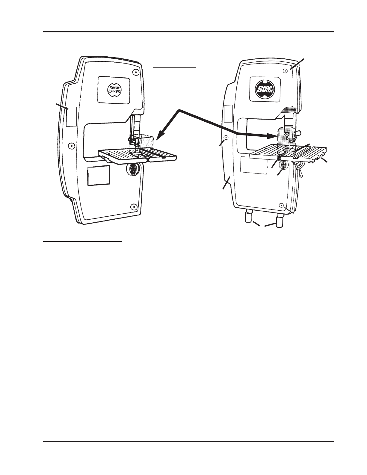
2. Your Bandsaw should look like Fig. 2
(with the table not yet installed). Remove
the three screws and washers then the
cover (6), as shown in Fig. 3.
3. Back out the setscrews (5) in the base of
the Bandsaw, as seen in Fig. 4. Place the
Bandsaw on the tubes, as seen in Fig. 5.
Don’t tighten the setscrews yet.
Fig. 2 Fig. 3
MOUNT AND ALIGN THE DRIVE
HUBS
4. If you have not already done so, mount a
drive hub on the Mark V headstock’s up-
per auxiliary spindle. Use the long hub
with a 5/8" center hole and four grooves in
the circumference.
Fig. 4
Fig. 5
5. Slide the Mark V headstock toward the
Bandsaw until the two drive hubs are 1/4"
apart, as illustrated in Fig. 6.
6. Horizontally align the Bandsaw hub (52)
to the Mark V hub by hand-rotating the
eccentric tubes, as seen in Fig. 7. You have
up to 1/4" movement to the right or left.
When the two hubs are horizontally
aligned, tighten the accessory mount lock,
as illustrated in Fig. 8.
7. Vertically align the Bandsaw hub to the
Mark V hub (shown in Fig. 9) by lifting the
Bandsaw until the tops of the hubs are at
the same height. When holding the
Bandsaw in vertical alignment, use a 5/
32"Allen wrench to tightenbothsetscrews,
as shown in Figs. 10 and 11. You may want
a helper to lift and hold the Bandsaw
while you are tightening the setscrews.
Fig. 6 Fig. 7
Fig. 8 Fig. 9
Fig. 10 Fig. 11

SHOPSMITH 11” BANDSAW 555943
Page 10
PREPARE THE BANDSAW AND
TABLE ASSEMBLY
8. Inspect the inside of the Bandsaw and
wipe away any dirt of foreign material.
Use a clean shop rag and mineral spirits or
turpentine,but becareful aroundtheblade.
It’s sharp!
9. When the table is clean, wax the top sur-
face and the miter gauge slots with paste
floor wax or paste furniture wax. Apply
wax sparingly, then buff it thoroughly. A
good coat of wax improves the machine’s
operation by helping the wood slide
smoothly over the table and the miter
gauge slide easily in the table slot.
NOTE
Don’t use car wax or spray furniture polish
on the Bandsaw. Car wax offers good protec-
tionfor metal, but it’s extremely hard andhas
little value as a lubricant. Furniture polish
isn’t hard enough. Paste floor wax or furni-
ture wax protects and lubricates.
10. Loosen the tilt lock (44) and lubricate the
trunnions (37) with powdered graphite,
rocking them back and forth as you apply
the graphite, as seen in Fig. 12. (You will
do this periodically, as discussed in the
Maintenance Schedule, on page 34.)
Fig. 12
Fig. 13
11. Apply graphite to lubricate the blade
tensioning screw (23), upper blade guide
post (71), and the threads of the upper and
lower blade guide adjusting knobs
(82,104).
We recommend powdered graphite for lubri-
cating the Bandsaw because it’s dry and
doesn’t attract sawdust. On some parts, oil
will mix with sawdust and form a gummy
substance that prevents these parts from op-
erating smoothly. However, if you can’t get
graphite, you can apply a light 10-wt. ma-
chine oil (such as sewing machine oil) spar-
ingly. Use only 1-2 drops. Apply oil to all the
parts that need lubrication, with the excep-
tion of the trunnions. If you don’t dust the
trunnionswithgraphite, youshould waxthem.
INSTALL THE TABLE
12. Position the trunnions (37) at approxi-
mately 25 degrees and lock them. Fig. 13
shows the exposed trunnions. Hold the
table (87) perpendicular to the blade, and
mount the table on the Bandsaw, as dem-
onstrated in Fig. 14. Make sure the table
leveling bolt (89) and the table insert (95)
are removed.
13. Insert a thin shim washer (48) between the
table (87) and each trunnion bracket.
14. Attach the table to the Bandsaw with bolts
(35) and thick washers (34), as shown in
Fig. 15. Finger tighten only.
Fig. 14

Page 11
SHOPSMITH 11” BANDSAW 555943
Fig. 18
Fig. 16
Fig. 19
15. Screw the socket head screw (91) in the
hole located at the back of the table, as
seen in Fig. 16.
16. Attach a hex nut (92) to the socket head
screw, as shown in Fig. 17.
Fig. 17
Fig. 15
Alignment
Your Shopsmith 11” Bandsaw comes to you
pre-aligned from the factory. It is important
to check all of the following alignment and
adjustment procedures, if you have prob-
lems with your cut accuracy. Also, it is impor-
tantto recheck themat regular intervals. These
steps are to be preformed using the already
mounted 1/4" wide blade and in the sequence
presented.
Tools Needed:
7/16" or adjustable wrench
5/32" Allen wrench
1/2" wrench
Precision square
Medium screwdriver
Medium Phillips screwdriver
Small (#0) Phillips screwdriver
WARNING
• The Bandsaw MUST be disconnected (or
unplugged) from its power source before per-
forming any alignment, adjustment, mainte-
nance or repair procedure. Do NOT rely
solely on the power switch.
• DO NOT install the power coupler at this time
or attempt to run the Bandsaw until you have
completed the remainder of the procedures in
thissection. It is dangerous torun the Bandsaw
until it is COMPLETELY aligned, adjusted
and inspected.
Blade Tracking System
Bandsaw blades revolve in an endless loop
on two wheels, the drive wheel (28) and the
idler wheel (24). Each of these wheels is
covered with a thin rubber tire to protect the
teeth of the blade and provide traction. The
idler (upper) wheel pivots on an arm (19), and
this arm is drawn upward by a flat spring (15).
17. Loosen and return the Bandsaw’s trun-
nion to “0”, where the table is supposed to
be perpendicular to the blade. Lock the
trunnion. See Fig. 18.
18. Install the leveling bolt (89) and knurled
nut (88) on the table, as in Fig. 19.

SHOPSMITH 11” BANDSAW 555943
Page 12
This mechanism compensates for slight in-
consistencies in blade length and tensions the
blade.
The tension is adjusted by turning the blade
tension screw (23) to the left of the idler wheel.
This screw moves the flat spring, increasing
or decreasing tension. The proper tension for
various blades is indicated on a scale above
the blade tensioning screw. See Fig. A-1.
Unlike many other bandsaws, blade tracking
for the Shopsmith Bandsaw is done automati-
cally with no need for adjustment. A roller
bearing to the right of the blade tension indi-
cator keeps the blade properly positioned on
the wheels.
A Bandsaw blade is supported and guided
from both above and below. See Fig. A-2. The
lower blade guide consists of a roller bearing
(98) to back up the blade and two guide
blocks (101,106) to keep it from twisting. Each
guide block is adjusted side-to-side by loos-
ening an Allen screw (100), and front-to-back
by turning the lower blade guide adjusting
knob (103). You need only to adjust the lower
blade guide roller bearing side-to-side. This
is done by loosening the mounting bolt (110).
The upper blade guide is similar, but it has
two additional adjustments. The upper blade
Fig. A-1
Fig. A-2
guide’s roller bearing (63) is adjusted front-
to-back by turning two screws (68). The blade
guide post (71) and roller bearing can be
adjusted side-to-side with the mounting bolts
(64). The entire assembly can be raised and
lowered after loosening the upper blade
guide’s height lock handle.
Aligning the Blade Tension Scale
The blade tension scale (12) is aligned at the
factory, and under normal conditions it
shouldn’t need adjustment. To check the
blade tension scale’s alignment, perform the
following steps:
NOTE
View the tensioning screw through the window.
1. Release the blade tension so the blade is
completely slack on the wheels.
2. Loosen the screw (10) near the top of the
scale, as seen in Fig. A-3.
Fig. A-3
Pivot Arm
Flat
Spring
Blade
Tension
scale
Blade
Tension
Screw
Auto-track
roller bearing
Upper
Wheel

Page 13
SHOPSMITH 11” BANDSAW 555943
3. Rotate the scale so it’s left edge (above the
notch) is parallel to and even with the red
indicator bar.
4. Hold the scale in position and tighten the
screw.
5. Re-tension the blade to the 1/4" setting on
the scale.
6. Spin the upper wheel (24) several times to
make sure the blade is turning freely.
Adjusting the Roller Bearings
The Shopsmith Bandsaw uses roller bearings
to keep the blade tracking properly on the
wheels and to provide support for the blade
during cutting operations. These bearings
are adjusted at the factory and should seldom
need further attention. However, it’s a good
idea to check the alignment of these bearings
each time you change blades.
You must mount and tension a blade in the
Bandsaw before you can properly adjust the
bearings. The blade should be centered on
the three roller bearings. The back of the
blade should rest against the auto-track roller
bearing. The lower blade guide’s roller bear-
ing. Also, the blade should be no more than
1/64" away from the upper blade guide’s
roller bearing. Be careful when you make
adjustments, since the blade is sharp.
Auto-Track Roller Bearing
The auto-track roller bearing (56) is near the
blade tension scale, at the upper left side of
the machine. The bearing guides the blade
onto the upper wheel. The front-to-back po-
sition of this bearing is fixed and shouldn’t be
altered. However, the mounting bracket can
be moved side-to-side so that you can center
the bearing behind the blade.
1. If the blade appears off center, loosen the
1/2" mounting bolt (59) that holds the
bracket (57) to the Bandsaw frame, as
shown in Fig. A-4.
Fig. A-4
2. Slide the bracket sideways until the slot in
the bearing is centered behind the blade
and tighten the mounting bolt.
3. Be careful to keep the sides of the bearing
parallel to the blade when tightening this
bolt.
Lower Blade Guide’s Roller Bearing
The roller bearing (98) directly below the
Bandsaw table serves two functions: It guides
the blade onto the drive wheel and it backs up
the blade beneath the table while you’re cut-
ting. Like the auto-track roller bearing, its
front-to-back position is fixed and shouldn’t
be changed. However, the entire lower blade
guide assembly, including the bearing, may
be adjusted side-to-side.
1. If adjustment is needed, loosen the guide
blocks (101,106)-if you haven’t done so
already-and pull them out about 1/16"
from the blade.
2. Loosenthe 1/2" mounting bolt (110) which
holds the lower blade guide assembly to
the Bandsaw frame, as seen in Fig. A-5.
The head of this mounting bolt can be
reached from the back of the Bandsaw, just
above the trunnion.

SHOPSMITH 11” BANDSAW 555943
Page 14
3. Slide the lower blade guide sideways until
the bearing is centered behind the blade,
tighten the mounting bolt, and reset the
guide blocks.
4. Again, be sure to keep the bearing parallel
to the blade as you’re tightening the bolt.
Adjusting the Upper Blade Guide’s
Roller Bearing
The upper blade guide’s roller bearing (63)
backs up the blade above the table. Unlike the
other two bearings, it can be adjusted side-to-
side and front-to-back.
1. Use a 7/16" wrench to remove the blade
guard, as shown in Fig. A-6.
Fig. A-5
2. Set the height of the upper blade guide to
about 1" above the table.
3. Use a 5/32" Allen wrench to loosen the
guide blocks. Pull them away from the
blade about 1/16".
Fig. A-6
Fig. A-7
4. Use a 1/2" wrench to loosen the two
mounting bolts (64) which hold the guide
post bracket (70) to the Bandsaw frame, as
seen in Fig. A-7.
5. Swing the upper blade guide sideways
until the bearing is centered behind the
blade, then tighten the mounting bolts.
The upper blade guide’s roller bearing
must also be adjusted so that it’s no more
than 1/64" away from the back of the
blade. This distance should remain the
same no matter what the position of the
upper blade guide is above the table.
6. Before you adjust the upper blade guide’s
rollerbearing front-to-back, check the dis-
tance from the bearing to the blade close
to the table and 5"-6" above the table.
7. If the upper roller bearing presses against
the back of the blade or if it’s farther away
than 1/64" at both the high and low posi-
tion, you’ll need to adjust the upper blade
guideroller bearing forward or backward.
If this distance is inconsistent or if the
bearing seems to press against the blade
more at one position than at the other, you
also need to change the tilt of the guide
post. Both adjustments are similar and
are performed at the same time.
8. Loosen the 1/2" jam nuts on the two guide
post adjusting screws (68), as seen in Fig.
A-8, then proceed in this manner:
Fig. A-8

Page 15
SHOPSMITH 11” BANDSAW 555943
Tomovetheguidepost and bearing closer
to the blade (without changing the tilt of
the guide post) turn both of the adjusting
screws an equal number of revolutions
counterclockwise.
To move the guide post and bearing away
from the blade (without changing the tilt
of the guide post), turn both of the screws
an equal number of revolutions clock-
wise.
9. If the bearing is not the same distance
away from the blade close to the table and
5"-6" above it, turn each screw equally in
opposite directions. This will change the
tilt of the guide post.
For example, to move the bearing closer
to the blade when the blade guide is at its
lower position, turn the top adjusting
screw clockwise, and the bottom adjust-
ing screw counterclockwise.
To move the bearing away from the blade
at this position, reverse the procedure.
Figs. A-9 and A-10 show making adjust-
ments.
Fig. A-9 Fig. A-10
Getting these adjustments just right may
take some time, but once you’ve got them
right they will seldom need attention.
Here are a few tips to help make this
procedure a little easier:
•Markyour starting positionwitha grease
pencilandturn the screws only 1/4 revo-
lution at a time until you see how much
the bearing moves with each minor ad-
justment.
•Be sure that when you lock the upper
blade guide height lock handle, the up-
per blade guide’s roller bearing does
not push the blade away from the lower
blade guide roller bearing.
•Each adjustment of the post will change
the tension on the upper blade guide’s
height lock. To adjust the lock tension,
follow the procedure described in “Ad-
justing the Upper Blade Guide’s Height
Lock” in this section. Once you’ve com-
pleted these adjustments to your satis-
faction,hold the screw from turning with
a screwdriver and tighten the jam nuts.
See Fig. A-11.
Check each roller bearing one more time.
Withthe bearings correctly adjusted,theblade
should ride in the center of all three of them.
The back of the blade should lightly contact
the auto-track roller bearing and the lower
blade guide’s roller bearing, and it should be
no more than 1/64" away from the upper
blade guide’s roller bearing no matter what
the position of that bearing is above the table.
10. Reattach the blade guide.
WARNING
Never attempt to operate the Bandsaw with-
out the blade guard in place.
Fig. A-11

SHOPSMITH 11” BANDSAW 555943
Page 16
Adjusting the Upper Blade Guide’s
Height Lock
The upper blade guide can be locked at any
height 0"-6" above the table. To change the
height of the blade guide:
1. Swing the upper blade guide’s height
lock handle 90 degrees to the right to
loosen the locking mechanism.
2. Adjust the upper blade guide so that it’s
no more than 1/4" above the surface of the
stock to be cut.
3. Lock the guide in place by swinging the
handle so that it points straight back (to-
ward the outfeed side of the table).
4. Ifthe movementof the upperblade guide’s
height lock seems stiff (or loose), you
need to adjust the tension on the locking
spring (72). This tension is set by a small
headless screw (73) in the left side of the
guide post retainer between the mount-
ing bolts. There should be enough ten-
sion to hold the guide post securely when
locked in place, but not so much that the
lock handle is difficult to operate or that
the guide post will not slide easily when
the lock is released. See Fig A-12.
•To increase the lock tension, turn the
adjusting screw counterclockwise.
•To reduce the tension, turn it clock-
wise.
NOTE
The tension on the blade guide’s height lock
is correctly set when you unlock the handle
and the upper blade guide drops smoothly
to 1/4"-1/2" above the tabletop, with no need
to pull it down.
Adjusting the Upper Blade Guide’s
Column Post Screw
The nylon screw (65) is adjusted at the at the
factory and should need only periodic check-
ing. It helps control side-to-side movement of
the column post within the column bracket.
Tightenthe nylon screw with a 3/8" wrench to
put more pressure on the column post (thus
eliminating more side to side movement”.
Loosen the nylon screw to put less pressure
on the column post. See Fig. A-13.
ADJUST THE T-SLOT EXTRUSION
1. Use a precision square to double check
your miter gauge for squareness. See Fig.
A-14. Adjust the miter gauge to be square,
if needed.
Figure A-12 Figure A-13
Figure A-14
Figure A-15
Figure A-16

Page 17
SHOPSMITH 11” BANDSAW 555943
2. Place the miter gauge in the table’s T-slot.
3. Use a 5/32" Allen wrench to remove the
expansion screw found in the center of the
miter gauge’s guide bar. See Fig. A-15.
4. Use a medium Phillips screwdriver to
adjust the tension of each of the five screw
(94) which attach the T-slot extrusion to
the table, as shown in Fig. A-16. The
tension should be such that the miter
gauge will both travel freely in the T-slot
and have a snug fit. After adjusting the
screws, replace the expansion screw in
the miter gauge guide bar.
ALIGN THE TABLE TO THE BLADE
1. With the miter gauge still in the T-slot,
place the precision square against both
the face of the miter gauge and the blade.
See Fig. A-17.
NOTE
The precision square’s “blade” must contact
the Bandsaw blade on either the blade’s
gullet or a tooth set away from the square. If
it is positioned on a tooth which is set toward
the square, alignment will not be accurate.
Figure A-17
2. Keep the square on the miter gauge, and
slide the miter gauge and square forward
until the base of the square reaches the
Bandsaw blade, as in Fig. A-18. If there is
agap between the square and the Bandsaw
blade or if the blade gets in the path of the
square, adjust the table (as the left hand is
doing in Fig. A-19) until the gap is elimi-
nated-or the blade is no longer in the path
of the square.
When the table is square to the blade, the
square’s blade should slide along the
Bandsaw blade without any gaps or inter-
ference. After you have adjusted the table,
recheck the table’s alignment by repeating
this step.
Figure A-18
Figure A-19
Figure A-20
3. Use a 1/2" wrench to securely tighten the
four bolts (35) attaching the table to the
Bandsaw. See Fig. A-20. It is easier to
tighten the front two bolts, then tilt the
table 15 degrees-25 degrees to tighten the
remaining two bolts. After tightening,
reset the table at 0 degree and lock the
trunnion.
NOTE
To assure the accuracy of the table’s align-
ment, test cut a piece of scrap wood and
check for squareness. If it is not square,
repeat Steps 2 and 3.
4. Remove the miter gauge from the table.
Then raise the Bandsaw’s saw guard all
the way and lock it.

SHOPSMITH 11” BANDSAW 555943
Page 18
5. Place a precision square along the side of
the blade and on the table, as in Fig. A-21.
6. If the blade is square to the table, use a 5/
32" Allen wrench to adjust the table height
screw (91) to touch the Bandsaw casting. If
the blade is not square to the table, loosen
the trunnion, make the necessary adjust-
ment and lock the trunnion. Now adjust
the table height screw. See Fig. A-22
Figure A-21 Figure A-22
Figure A-23
7. Hold the table height screw in place, while
you use a 1/2" wrench to tighten the hex
nut against the table, see Fig. A-23.
ALIGN THE TABLE SCALE TO THE TRUN-
NION SCALE
1. If the “0” marks on the table scale and the
Bandsaw’s trunnion scale so not align, use
a medium Phillips screwdriver to slightly
loosen the table scale’s screws (32), as
shown in Fig. A-24. Align the “0” marks
and retighten the screws.
ADJUST THE BLADE GUIDES
1. Turn the blade guide adjusting knobs,
shown in Figs. A-25 and A-26, until the
front edges of the guide blocks are just
short of the bottom of the gullets between
the teeth, as illustrated in Fig. A-27. If the
guide blocks extend beyond the gullets,
the teeth will nick the sides of the blocks,
wearing away the blade guides and dull-
ing the blade.
Figure A-24
Figure A-25
Figure A-26
Figure A-27
2. With the locking screws (76,100) loose,
push each of the four guide blocks-two in
the upper blade guide and two in the
lower blade guide-toward the blade until
they just barely clear it on each side. This
clearance should be about .003-.005". Figs.
A-28-A-31 show adjusting the four guide
blocks.
An easy way to gauge the distance of the
blades from the blocks is with tape. Put a
piece of cellophane tape on each side of
the blade, then push the blocks in until
they touch the tape. Tighten the locking
screws and remove the tape. Again, refer
to Figs. A-28-A-31. Many woodworkers
use notebook paper or a crisp dollar bill to

Page 19
SHOPSMITH 11” BANDSAW 555943
gauge the guide clearance. Use which-
ever works best for you.
Be careful that the guide blocks do not
press the blade to one side or the other.
The blade should not be deflected when
the blocks are properly set, as shown in
Fig. A-32.
NOTE
Adjust the blade guides very carefully:
−−
−−
−If the guide blocks are too close to the
blade or too far forward, the blade guides
may interfere with the running blade.
−−
−−
−If the guide blocks are too far apart or too
far back, the blade may “lead”-wander off
the pattern line to one side or the other.
−−
−−
−If you’re sure the blade guides are prop-
erly adjusted and the blade does not operate
freely, check if the blade is bent or has a
“high spot” at the weld.
−−
−−
−If the blade continues to lead no matter
how you adjust the guides, follow the proce-
dure described in “Correcting Blade Lead”
in the Troubleshooting section on page 34.
Figure A-28
Figure A-29
Figure A-30
Figure A-31
Figure A-32
3. Spin the upper (idler) wheel by hand to be
certain the blade guides don’t interfere
with the action of the blade. Also, watch
the blade as it slips between the guide
blocks. Check that the teeth remain in
front of the blocks throughout the revolu-
tion of the blade. If the blade does not spin
freely or the teeth stray behind the blocks,
readjust the blade guides.
WARNING
Use only Shopsmith Bandsaw blades for your
Bandsaw. If you use other blades, be certain
that they are of premium quality, are 72" long
(plus or minus 1/2"), and are between 1/16" and
5/8" wide. ANY OTHER BLADES ARE UN-
SAFE. Also, when using 1/16" blades, you must
install Cool Blocks (Part No. 555374) in place of
the standard metal blade guides.
INSTALL THE TABLE INSERT
1. The table insert (95) has two clips on its
underside, as shown in Fig. A-33. Put the
blade into the insert’s slot so the solid part
of the insert is on the blade’s tooth side.
Figure A-33

SHOPSMITH 11” BANDSAW 555943
Page 20
2. Clip the insert in its hole, as in Fig. A-34,
with the clips going into the table first.
Figure A-34
Figure A-35
Figure A-36
3. Snapdown the front of the insert, as shown
in Fig. A-35.
4. Use a very small Phillips screwdriver (96)
to adjust the leveling screws (90) through
holes in the insert so it is uniformly flush
with the edge of the Table. See Fig. A-36.
5. Reattach the Bandsaw cover with the three
screws and washers.
Alignment and Adjustment
Safety Checklist
When you’ve finished aligning and adjusting the
various parts of your Bandsaw, review your
work according to this checklist. Make copies of
it and perform each item before operating you
Bandsaw, especially when it has set idle for more
than a few days.
1. Is the Bandsaw blade properly mounted and
tensioned.
2. Is the blade centered on the roller bearings?
Does it rest against the auto-track roller bear-
ing and lower blade guide’s roller bearing,
while remaining no more than 1/64" away
from the upper blade guide’s roller bearing?
3. Are the blade guides properly adjusted?
4. Is the height of the upper blade guide’s height
lock properly adjusted?
5. Is the upper blade guide positioned no higher
than 1/4" above the stock, and is locked
securely in place?
6. Does the blade operate freely?
7. Is the table insert in place and flush with the
table top?
8. Is the table properly aligned to the blade?
9. Is the table adjusted to the correct work angle
and is the tilt lock secured?
10. Are the drive hubs properly aligned?
11. If you’re using the Mark V or Power Station
to power the Bandsaw, is the power coupler
installed correctly? Are both the accessory
mount lock and the headrest lock tightened
on the Mark V? Is the carriage locked on the
Power Station?
12. If you’ve mounted the Bandsaw on a Power
Stand, is the V-belt properly tensioned and
the pulley guard in place?
This manual suits for next models
1
Table of contents
Other Shopsmith Saw manuals


