ShoreStation DA0075-15 User manual

Document Number: 0004084
Rev. 3 (2016-6-24)Page 1
S H O R E S T A T I O N L A K E F R O N T S Y S T E M S
Solar ShoreLights
Models: DA0075-15, DA0076-15, DA0077-15,
DA0079-15, and DA0080-15
Introduction
ShoreStation Solar Shore Lights are the fastest and
easiest way to begin enjoying the safety, security and
comfort of waterfront lighting. No costly power supply installation. No
hassles with battery tending. Just sit back, relax and enjoy time with
family and friends.
This unique light is totally powered by the sun eliminating the need for
power on the waterfront. The light installs quickly to your ShoreStation dock
or on shore and provides the equivalent light output of a 40W light bulb.
The LED light source is rated for 50,000 hours of use and attracts fewer
bugs than an incandescent light bulb.
This manual provides installation, operating and care instructions for all mounting
applications on ShoreStation dock and on shore. Please read this manual thoroughly
before installing and operating your light.
Safety Instructions
DO NOT INSTALL OR USE THIS LIGHT BEFORE YOU FIRST STUDY MANUAL AND
UNDERSTAND THE INFORMATION CONTAINED IN IT.
1. Do not assemble the light unless you have read and understand all service
instructions.
2. The system contains a 12V, 9Ah battery that is rated NON-SPILLABLE by DOT
(Department of Transportation), ICAO (International Civil Airline Organization) and IATA
(International Airline Transportation Association) definitions.
3. The battery cannot be serviced. The battery must be replaced when it has reached
the end of its service.
4. When replacing the battery, remove wrist watches and jewelry, which might make
electrical contact with the battery.
5. Keep batteries away from children.
6. Caution: Tipping hazard!
Only use original base or post.
Check all accessory connections to the dock to ensure the post is rigidly
attached to the dock system.
Contents
Introduction
Safety Instructions
Specifications
Preparation
Assembly Instructions
Installation Instructions
Operation Instructions
Optional Light Settings
Care of your Solar Light
Troubleshooting
Midwest Industries, Inc.
122 E State Hwy 175
Ida Grove, IA 51445
(800) 859-3028
www.shorestation.com
Document Number: 0004084
Rev. 3 (2016-6-24)Page 2
S H O R E S T A T I O N L A K E F R O N T S Y S T E M S
Specifications
Light Output
450 lumens
Operating Temperature
-20° F to 140° F
Light Rating
50,000 hours
Battery Regulatory
Approval
D.O.T., I.A.T.A., F.A.A., C.A.B.,
& UL M20845
Battery Style
Sealed Rechargeable
Solar Panel Voltage
12V
Battery Voltage
12V
Solar Panel Power Rating
20W
Battery Capacity
9Amp/Hr
Preparation
Location, location, location…
Many variables will affect the operatingtime of the light. The time of year, location (geographic), and
environment will affect the power available from the sun. Obviously the time of year will cause the length of
time the sun is available to decrease and increase with the season. The further from the equator you are
geographically, the more variation you will experience.This light is designed for use during summer
months in the Northern US states. This system should provide 6 hoursof operation after a sunny, summer
day. Overcast days will provide some charging, but the length of time for light output will be reduced.
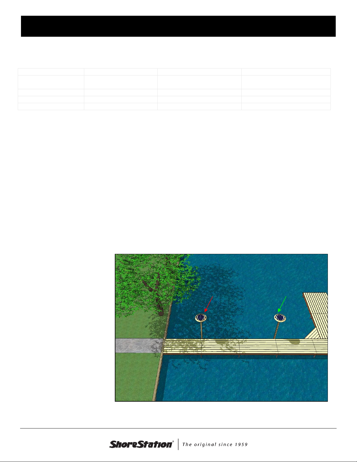
Care should be taken when selecting your installation location. Shade is an enemyof solar panels and
should be avoided. Observe your location and select an area that receives as much sunlight as possible
during the day. Also avoid any other large sources of light during evening hours. This may cause the
controller to switch off the
light.
The system is provided with
an on/off switch. This gives
you the option of turning the
system off to save the charge
for early morning use orto
ensure the system is fully
charged for special events or
weekends.
Shade will reduce the
performance of the light
Bad location
Good location


Document Number: 0004084
Rev. 3 (2016-6-24)Page 4
S H O R E S T A T I O N L A K E F R O N T S Y S T E M S
STEP 1
Remove all packaging and sort all
hardware.
The Light Assembly is preassembled
and ready to operate after the
connection of the battery and solar
panel to the controller. To make the
connections, carefully flip the light
assembly over and loosen the 4
retaining bolts until the retainer clips
can be easily rotated.
Retain clips on top of light assembly
Loosen four bolts until retainer clips
can rotate.
Twist the retainer clips to allow
removal of the panel
Document Number: 0004084
Rev. 3 (2016-6-24)Page 5
S H O R E S T A T I O N L A K E F R O N T S Y S T E M S
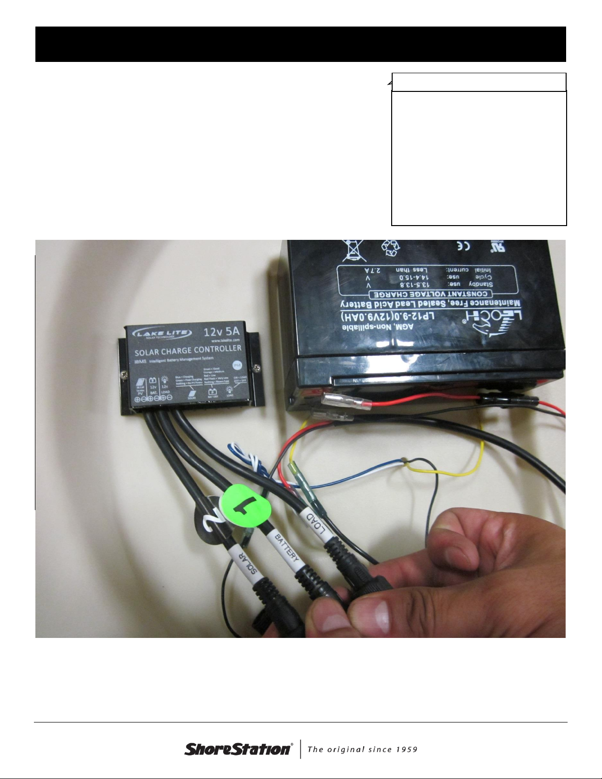
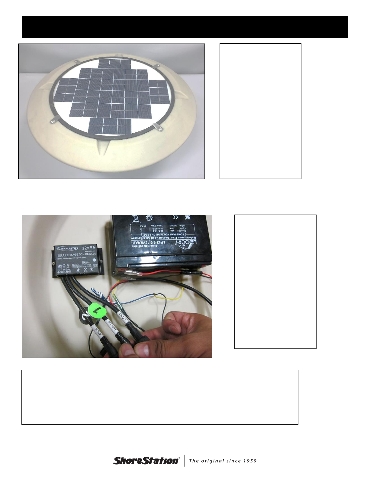
Connect the wires Battery are number 1, then hook the Solar panel number 2, and last hookup the
connections marked load.
STEP 2
Carefully lift the solar panel from the
plastic base. This will expose the
interior components of the light.
Connect the harness connection as
shown.
Expose the panel to sunlight and
verify that the green charge
illuminates on the charge controller.
Solar Panel

Document Number: 0004084
Rev. 3 (2016-6-24)Page 6
S H O R E S T A T I O N L A K E F R O N T S Y S T E M S
Retain clips on top of light assembly
STEP 3
Carefully put the solar panel back
onto the plastic base. Be sure no
wires are between the bottom of the
panel and the battery.
Twist the retainer tabs back over the
panel and retighten the retainer bolts.
The light assembly is now ready to
be mounted on the post.
Document Number: 0004084
Rev. 3 (2016-6-24)Page 7
S H O R E S T A T I O N L A K E F R O N T S Y S T E M S
Dock Light Post Assembly Instructions
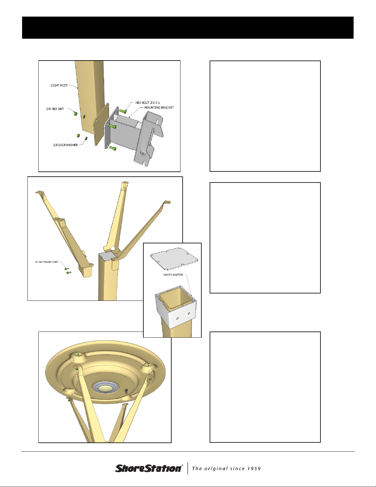
STEP 1
Remove all packaging and sort all
hardware.
Use the hardware provided to
assemble the MOUNTING
BRACKET to the LIGHT POST as
shown.
NOTE: Freestanding dock
mounting bracket shown.
Skip this step for the Gear Tower
Light (DA0077).
STEP 2
For the DA0077 Gear Tower
accessory and the DA0080 retrofit
light, place the adaptor on the post
supplied with the light (see inset).
This is not required for the other
accessories.
Place COVER PLATE on the top of
the LIGHT POST.
Use a power drill to assemble the
MOUNTING LEGS to the post using
the self-drilling screws
STEP 3
Assemble the LIGHT ASSEMBLY to
the MOUNTING LEGS by aligning
the pre-assembled bolts to the hole
on the top of the legs. Fasten using
the 1/4” nuts provided.

Document Number: 0004084
Rev. 3 (2016-6-24)Page 8
S H O R E S T A T I O N L A K E F R O N T S Y S T E M S
Installation Instructions
Your solar light includes one of the following styles for mounting: Pedestal, Dock Post, FloatingDock Post,
Gear Tower, and Retro-fit. Choose the appropriate instruction for the solar light style you purchased a
separate parts list is available for each.
Freestanding Dock DA0075-15
Align the mounting bracket with the leg frame. Push the bracket under the side of the dock and lift up until
the bracket contacts the side of the dock. Push the bracket over the leg and set it down onto the ‘ears’
attached to the leg frame. Verify that the top and bottom of the bracket are seated on the top and bottom
‘ears’ of the frame.
Verify that
the top and
bottom are
seated.
Document Number: 0004084
Rev. 3 (2016-6-24)Page 9
S H O R E S T A T I O N L A K E F R O N T S Y S T E M S
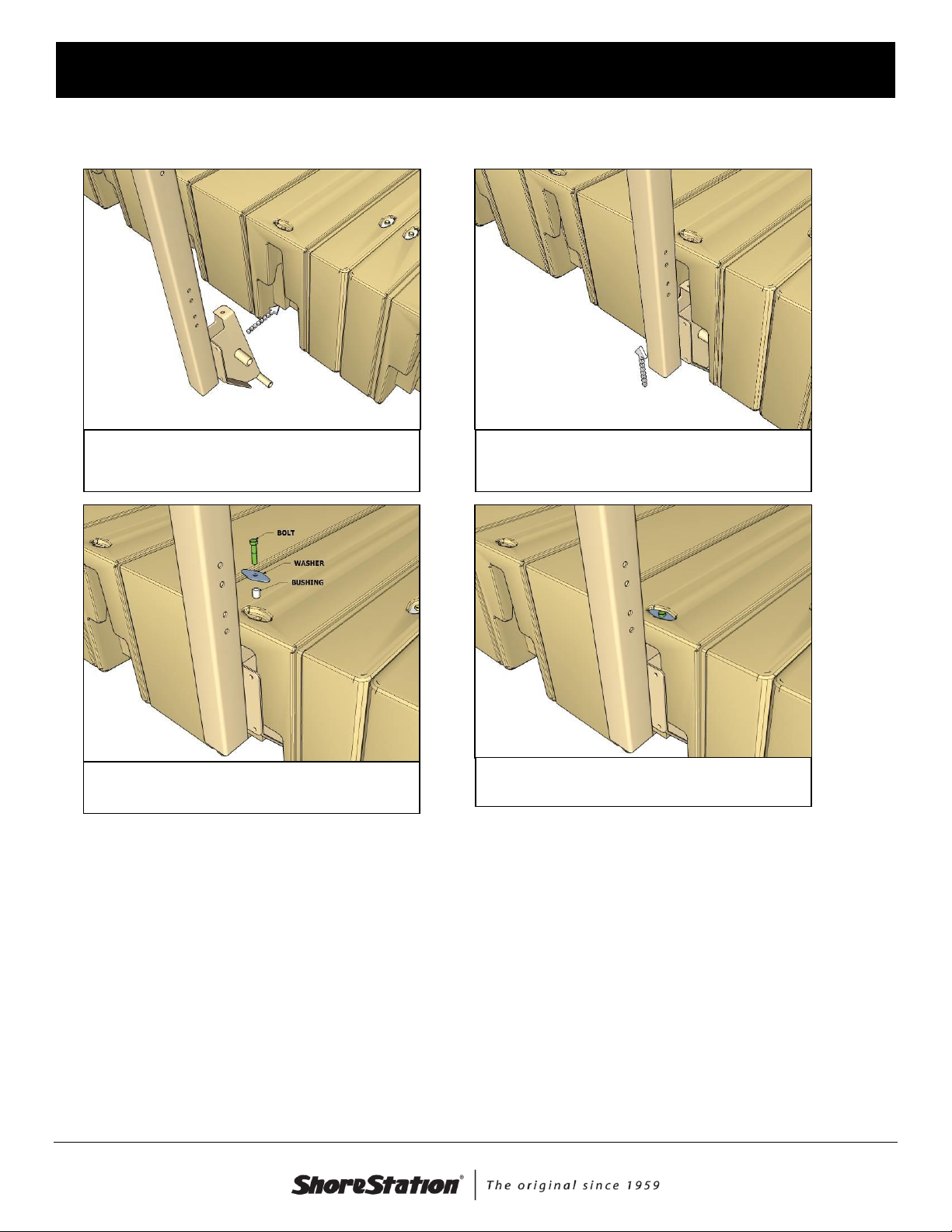
Floating Dock DA0076-15
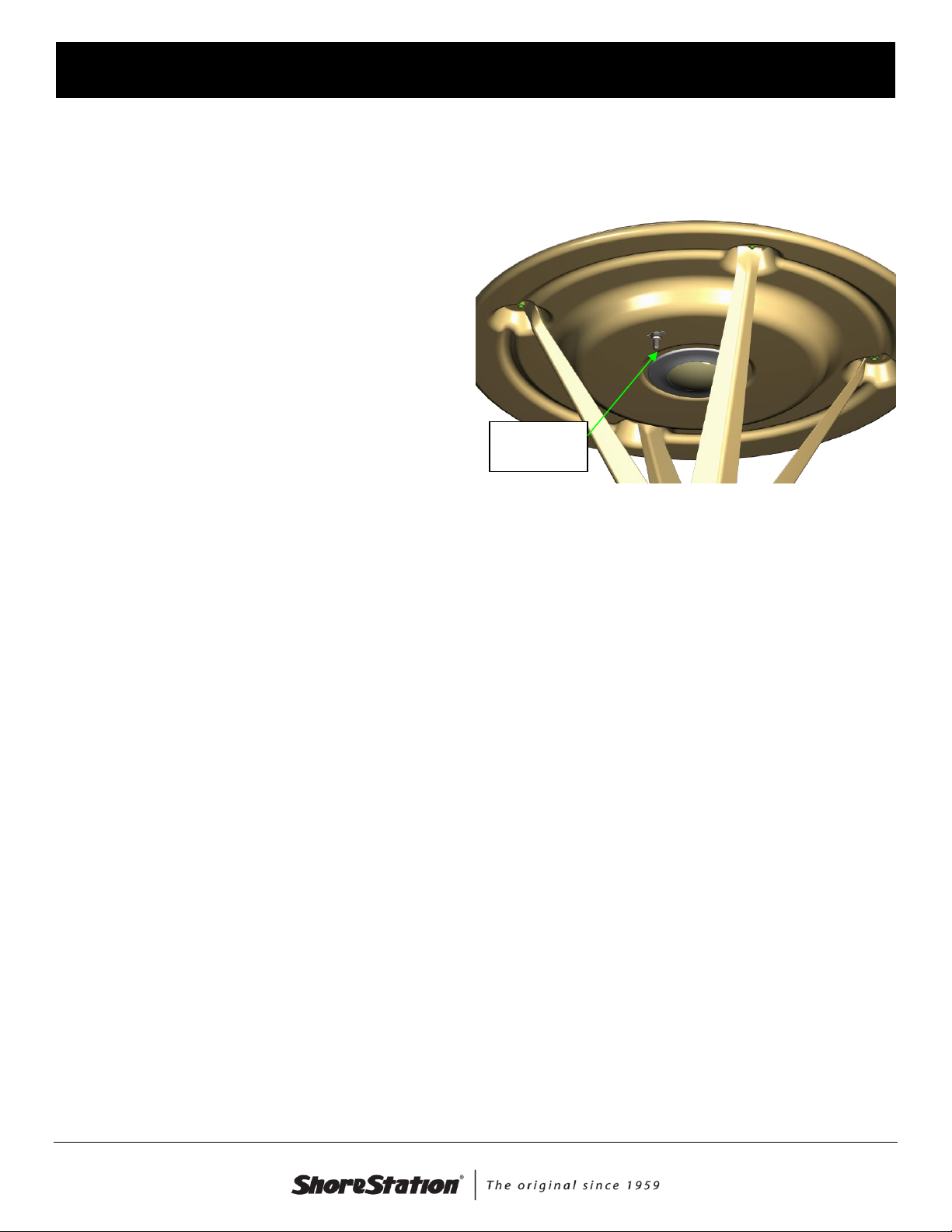
Step 1: Align accessory bracket with the
socket.
Step 2: Slip connector into socket and pull
up.
Step 3: Install the bushing, washer, and bolt
as shown.
Step 4: Tighten the bolt to 25 ft.-lbs.

Document Number: 0004084
Rev. 3 (2016-6-24)Page 10
S H O R E S T A T I O N L A K E F R O N T S Y S T E M S
DA0077-15 - Gear Tower
Assembly
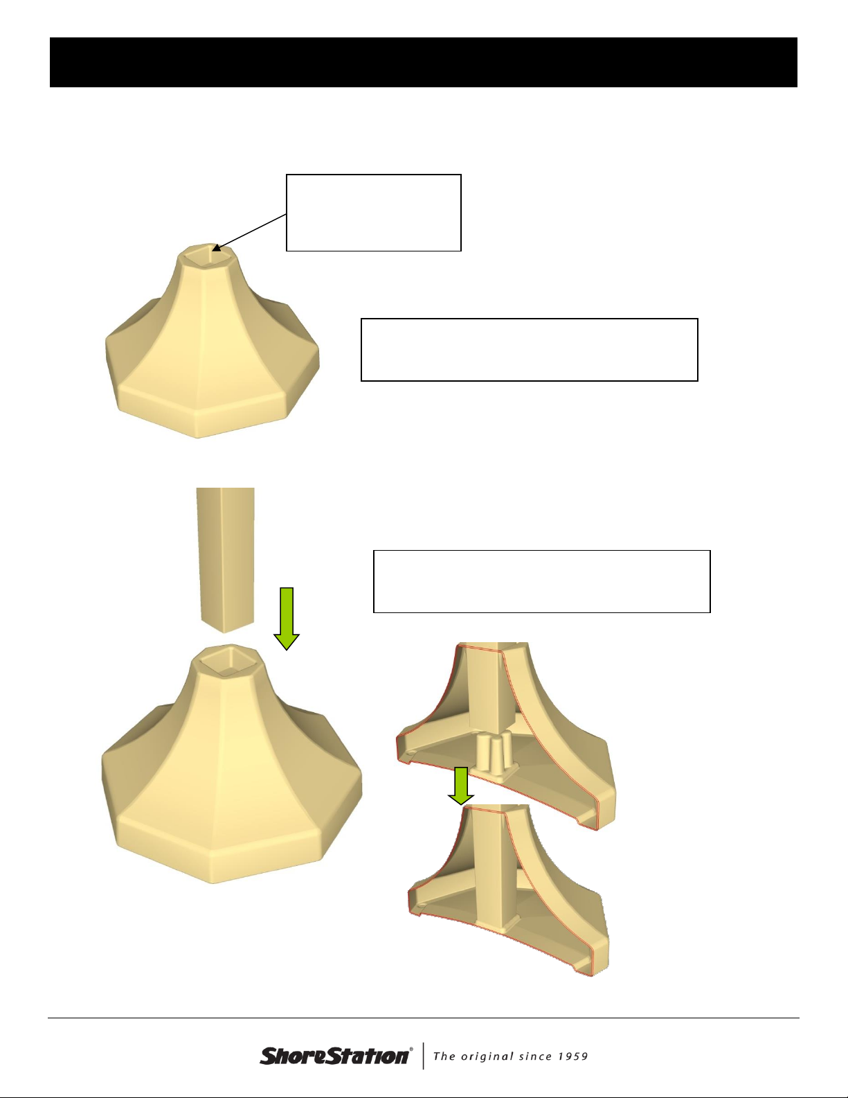
Step 1: Remove the plastic cover from your gear
tower. This will expose the pre-cut hole on the
surface.
Step 2: Insert the post into the opening and loosely
assemble the top u-bolt to the post.
Step 3: Adjust the post height until you have about 4”
of post exposed under the tower surface. Tighten the
top u-bolt.
Step 4: Assemble the bottom u-bolt, lock washers,
hex nuts, and caps to the bottom of the post. Refer to
Step 2.

Document Number: 0004084
Rev. 3 (2016-6-24)Page 11
S H O R E S T A T I O N L A K E F R O N T S Y S T E M S
DA0080-15 – Retro-fit Replacement Light
The DA0080 Light kit is intended to replace existing ShoreStation light accessories equipped with a 3”
square post. To install, refer to steps 2 & 3 of the Assembly Instructions section of this document.
The DA0080 can also mount to a standard 4x4 wood post (actual dimensions approximately 3.5”x3.5”).
Step 5: Assemble the self-drilling screw into the post
using a power drill with a 3/8 socket.
Document Number: 0004084
Rev. 3 (2016-6-24)Page 12
S H O R E S T A T I O N L A K E F R O N T S Y S T E M S
DA0079-15 ShoreLight Pedestal Assembly Instructions
Fill the post base with
enough water or sand to
produce 80 lbs of total
weight.
If you live in a climate that experiences freezing
temperatures, RV-type antifreeze should be added
to the water to prevent freezing.
Slip the light and post assembly into the filled base.
Be sure the post seats into the base as shown.
Document Number: 0004084
Rev. 3 (2016-6-24)Page 13
S H O R E S T A T I O N L A K E F R O N T S Y S T E M S
Operating Instructions
On/Off Switch
Your solar light comes equipped with a simple
on/off switch. The light has been shipped to you
with the switch in the ‘off’ position. For best results,
allow the light to charge for two days prior to
switching to the ‘on’ position. This ensures battery
has been sufficiently charged to operate system
reliably. This is easily accomplished by placing the
light fixture outside in full sun for a couple days with
the switch in the ‘off’ position. The system WILL
continue to charge even with the switch in the
‘off’ position.
Solar Light Controller
Your solar light is equipped with a solar light controller that automates the charging of the battery and
on/off switching of the light making operation of the light simple and easy. This controller has the following
features:
Automatic sunlight sensing for light and charge control - The system will automatically turn the
light on at dusk and off at dawn.
Automatic charge control –The controller will automatically regulate charging to maximize the
battery life and avoid discharging of the battery during low light conditions.
Automatic discharge control –The light will automatically turn off before the battery is discharged
to the point of damage.
Temperature compensation –The controllerwill automatically change the charging parameters
based on the ambient temperature. This protects the battery from damage during low or high
temperature conditions.
The solar light controller has been preset at the factory for dusk-to-dawn operation. The light fixture will be
turned on at dusk and remain on until dawn OR the batterycharge has been depleted.The actual ‘on’ time
for your light will depend on your local conditions.Weather and seasonal conditions will cause the
performance to vary.
Battery
The solar light contains one, sealed 12V, 9Ah battery. This spill-proof battery is maintenance free and will
provide 3-5 years of reliable service.
ON/OFF
Switch


Document Number: 0004084
Rev. 3 (2016-6-24)Page 15
S H O R E S T A T I O N L A K E F R O N T S Y S T E M S
Care of your Solar Light
Solar Panel
One of the wonderful things about solar panels is there’s very little maintenance! Visually inspect the top of
the light fixture for dustand debris. Wipe clean with a household glass cleaner if the solar panel is dirty.
Storage
Your system can be stored outdoors during winter months.
The solar charge controller included in the system
compensates for temperature variation to ensure the
battery remains charged. To best protect your battery from
damage, make sure the light is stored in a location where
it can receive sunlight during the storage months with the
switch in the ‘OFF’ position. This will keep the battery
charged and ensure it is not damaged by temperature
extremes.
If your location will experience temperatures -20°F or
lower, it should be stored indoors where the temperature
will stayabove -5°F. If you plan to store your panel
indoors, make sure the switch is in the ‘off’ position and
allow the system to charge in full sun for two days prior to
moving indoors. This will prevent damage to the battery.
Avoid storing the system indoors formore than 6 months.
Doing so may cause damage to the battery.
Battery Replacement
Eventually, your battery will reach the end of its life. Your battery life will vary due to variation in the
conditions in your area. Replacement batteries are readily available for your solar light. Only use an
equivalent sealed battery as a replacement. Contact your local ShoreStation dealer for replacement
information.
Replacement Specifications:
Battery Style
Sealed Rechargeable
Battery Voltage
12V
Battery Capacity
Minimum of 7Amp/Hr (9 Ah recommended)
Clean the panel
occasionally
Document Number: 0004084
Rev. 3 (2016-6-24)Page 16
S H O R E S T A T I O N L A K E F R O N T S Y S T E M S
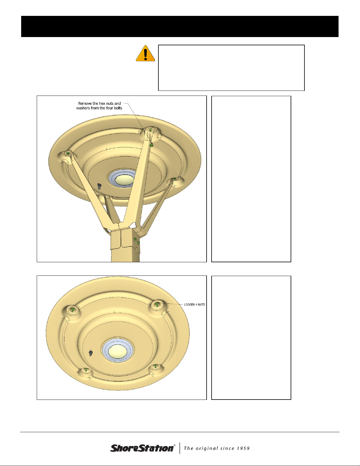
Instructions:
Remove all wristwatches and jewelry
before handling any battery. These
items can make contact with the battery
terminals causing a short-circuit
resulting in serious injury
Remove the light
fixture from the dock
and move to a flat, dry
location. Carefully lay
the light on the ground.
Remove the 4 hex nuts
and washers from the
bottom of the light
assembly.
Remove the light
assembly from the
post.
Notice the four
additional hex nuts.
Loosen all four. Do not
remove the nuts.
Document Number: 0004084
Rev. 3 (2016-6-24)Page 17
S H O R E S T A T I O N L A K E F R O N T S Y S T E M S
Twist the retainer clips
on the top of the light
assembly.
Carefully tilt the solar
panel from the light
assembly as shown.
Care should be taken
not to pull the wires
while tilting the panel.
Identify the battery in
the center of the light
assembly.
Disconnect the red and
black wires from the
battery.
The battery is attached to the light assembly with Velcro. Pull the battery from the
assembly.
Locate your replacement battery and attached the Velcro provided with it (ShoreStation
Replacement Kit).
Document Number: 0004084
Rev. 3 (2016-6-24)Page 18
S H O R E S T A T I O N L A K E F R O N T S Y S T E M S
Attach the Red wire you removed from the battery to the positive pole of the new battery. Attach the Black
wire to the negative pole.
Reverse the instructions to re-assemble the light. Make sure the wire connectors do not get
‘sandwiched’ between the battery and controller when re-assembling the light.
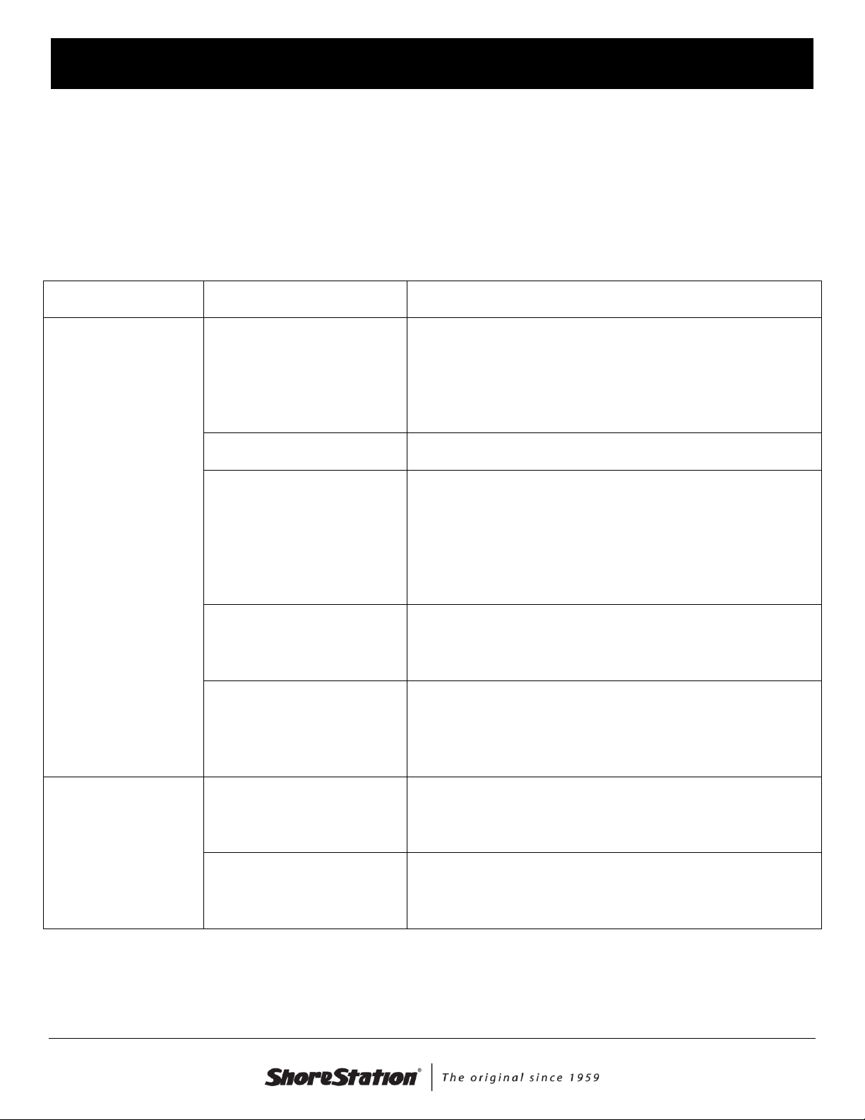
Troubleshooting
Problem
Possible Issue
Possible Resolution
Light does not turn
on.
Too much light
Check to make sure the ON/OFF Switch is ON and test
the light by temporarily covering the solar panel with a
piece of cardboard. If the light turns on, it is not quite
dark enough for the light to turn on. Make sure your
light is not located under another light source.
ON/OFF Switch is OFF
Check to make sure the ON/OFF Switch is ON
Discharged Battery
Your battery may be discharged below the level the
controller will allow. Move the light switch to the OFF
position for a couple of days and try the light again. If
the problem is recurring, you may not have the light
located well (not enough light) or the battery may be
close to the end of its useful life.
Bad Battery
If the above itemsdo not remedy the problem, contact
ShoreStation to get information on a replacement
battery.
Disconnected Battery
The battery may have become disconnected during
transportation. Refer the Battery Replacement section
for instructions on opening the light assembly. Check
the battery connections in the assembly.
Short lighting
duration
Insufficient sunlight
The light system is designed to run up to 7 hours after a
full day of bright, summer sun. If you experience an
overcast day, this duration will be shorter.
Bad Battery
The battery in the system should last 3-5 years. The
battery in your system may have reduced capacity due
to its age or condition.
If the problems stated above do not describe the issues you are experiencing, contact ShoreStation at
(800) 859-3028.

Document Number: 0004084
Rev. 3 (2016-6-24)Page 19
S H O R E S T A T I O N L A K E F R O N T S Y S T E M S
ShoreLight Solar Light Limited Warranty
ShoreStation warrants - to the original end-user - the ShoreLight Solar Light, for one
(1) year from date of purchase against the following points.
To be free of defects in material and workmanship on all components,
manufactured or purchased.
To perform properly under normal usage, when fully assembled and used
according to the instructions provided at the time of purchase.
This warranty covers, at the manufacturer’s discretion, repair or replacement of
the defective parts.
What this ShoreStation Warranty does not cover:
Manufacturer does not cover poor performance resulting from geographic
location and other environmental factors out of its control.
Manufacturer does not cover fading or discoloring from exposure to the
elements.
Manufacturer does not cover consequential damages.
Manufacturer does not cover cost of freight for returned ShoreLight.
Manufacturer’s warranty does not apply to any products that have been
subjected to an accident, adjustment, improper installation, misapplication,
misuse, modification, neglect, repair, including –but not limited to –improper
maintenance, or use of unauthorized parts.
To the Purchaser:
Should you have a warranty claim, we ask that you work your claim through your
dealer. ShoreStation may require your dealer to provide a photograph or, in some
cases, to return the ShoreLight to the manufacturer for review. In order for the claim to
be initiated, original sales receipt must accompany warranty claim. Shipping costs are
not reimbursed for substantiated or unsubstantiated claims.
This manual suits for next models
4
Popular Outdoor Light manuals by other brands

Kichler Lighting
Kichler Lighting HELEN 37536 instructions

Thorn
Thorn OXANE L installation instructions

esotec
esotec Solar Globe Light multicolor 20 operating instructions

mitzi
mitzi HL200201 ELLIS Assembly and mounting instructions

HEPER
HEPER TILA S AFX 3 Module Installation & maintenance instructions

Designplan
Designplan TRON 180 installation instructions


BEGA
BEGA 84 253 Installation and technical information

HEPER
HEPER LW8034.003-US Installation & maintenance instructions

HEPER
HEPER MINIMO Installation & maintenance instructions

LIGMAN
LIGMAN BAMBOO 3 installation manual

Maretti
Maretti TUBE CUBE WALL 14.4998.04 quick start guide

Maxim Lighting
Maxim Lighting Carriage House VX 40428WGOB installation instructions