showermate U2.6 User manual

Installation Instructions
For Showermate Universal
Single & Twin Pumps
U2.6 bar Single U1.8 bar Twin
U2.6 bar Twin
INDEX . . . . . . . . . . . . . . . . . Page No
Product Description. . . . . . . . . . . . . . . . . . . 1
Application. . . . . . . . . . . . . . . . . . . . . . . . . . 1
Storage . . . . . . . . . . . . . . . . . . . . . . . . . . . . 2
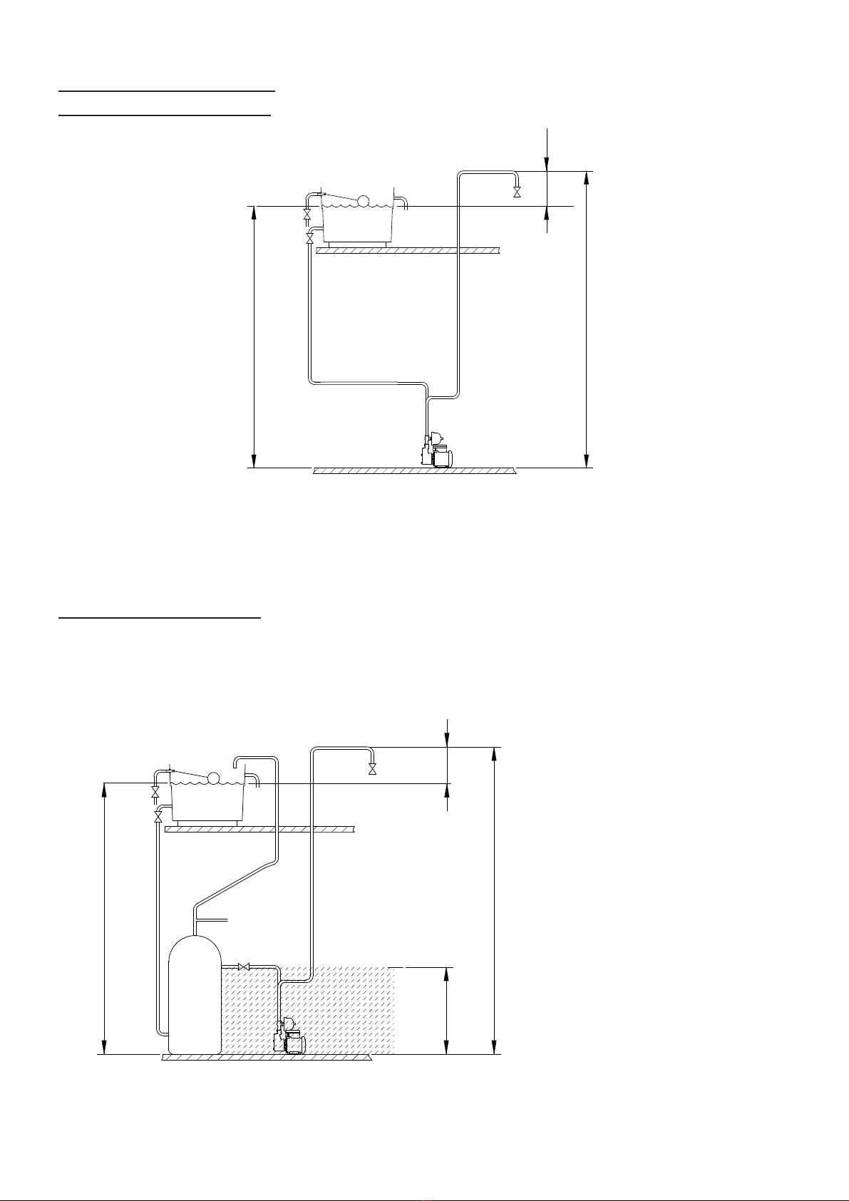
Typical Installation. . . . . . . . . . . . . . . . . . . . 2
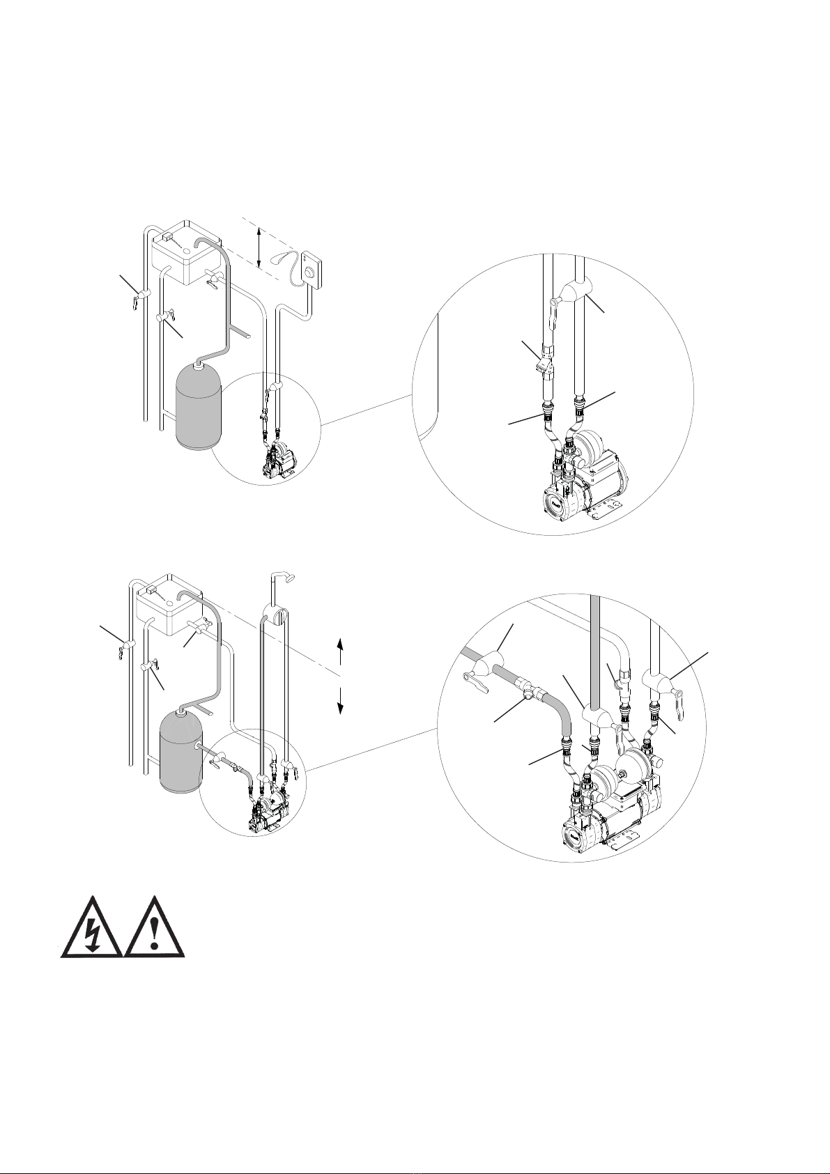
Pump Location. . . . . . . . . . . . . . . . . . . . . . . 3
Pipework . . . . . . . . . . . . . . . . . . . . . . . . . . . 7
Pump Connections . . . . . . . . . . . . . . . . . . . 8
INDEX . . . . . . . . . . . . . . . . . Page No
Electrical Installation . . . . . . . . . . . . . . . . . . 12
Commissioning . . . . . . . . . . . . . . . . . . . . . . 15
Maintenance . . . . . . . . . . . . . . . . . . . . . . . . 16
Technical Specification . . . . . . . . . . . . . . . . 18
Noise . . . . . . . . . . . . . . . . . . . . . . . . . . . . . . 19
Trouble Shooting Guide. . . . . . . . . . . . . . . . 19
Environment Protection . . . . . . . . . . . . . . . 20
PRODUCT DESCRIPTION
Electric motor driven single or twin ended peripheral pumps complete with an automatic
control system, consisting of flow switches, pressure switches, pressure vessels and
electronic control.
APPLICATION
Showermate Universal pumps are suitable for positive or negative head installation
conditions. The pumps are designed for single shower pressure boosting applications in
vented stored water systems. Inlet pressures to the pump and ambient temperatures must
not exceed the values given in the technical specifications.
This pump set must not be used for any other application without the
written consent of Stuart Turner Limited and in particular, must not be
connected directly to the mains water supply.
This appliance is not intended for use by persons (including children)
with reduced physical, sensory or mental capabilities, or lack of
experience and knowledge, unless they have been given supervision
or instruction concerning use of the appliance by a person responsible
for their safety.
Children should be supervised to ensure that they do not play with the
appliance.
WARNING - Washer/condenser dryers and condenser dryers.
The pump must not be used in the water supply line to a washer/
condenser drier or a condenser drier, which uses a constant flow of
cold water to aid the condenser drying process, as damage can occur
to the pump. If in doubt or for further information contact Stuart
Turner Ltd.
Please leave this instruction booklet with the pump as it contains
maintenance and safety information (Original Instructions)

- 2 -
STORAGE
If this product is not to be installed immediately on receipt, ensure that it is stored in a
dry, frost and vibration free location in its original packaging.
TYPICAL INSTALLATION
(Universal Single & Twin Pump System)
The plumbing
installation
must comply with the following:
The Water Supply (Water Fittings)
Regulations 1999.
BS6700 and building regulations.
Be installed by a competent person.
If in doubt consult Stuart Turner Ltd.
These diagrams should be used for
schematic reference only
Item 1 = System service valves (not
supplied) should be fitted.
Item 2 = Flexible hoses (supplied).
Item 3 = Inline strainer (not supplied.)
Negative
Head
NegativeHead
Positive Head
1
1
Fig. 1
1
2
2
3
Fig. 2
1
11
111
222
3
3

- 3 -
STEP 1: PUMP LOCATION
WARNINGS:
Pump Location
If possible site the pump in a location where in the unlikely event of a
water leak, any spillage is contained or routed to avoid electrics or
areas sensitive to water damage.
Care should be taken to protect pump from frost and freezing,
particularly when located in a loft installation.
The motor casing can become hot under normal operating conditions,
care should be taken to ensure it cannot be touched during operation.
The pump must not be located where the static pressure on the inlet
or outlet to the pump is greater than permitted. Should the
installation exceed these limits, contact Stuart Turner for further
advice.
The pump must be installed so that the following conditions are met:
Locate the pump in a dry, frost free position where it cannot be sprayed with water. It
should be positioned horizontally on its anti-vibration mounting feet and should not be
screwed down. It should be positioned as close to the water source as possible having a
minimum flooded suction head of 0.5 metres at all times.
Ensure the pump is mounted in a position that allows easy access to it, if required.
Ensure the water flow is in the direction of the arrow that is marked on the flow switch
reed clamp (vertically upwards).
Before deciding where to position the unit, check to ensure the static inlet and outlet
heads of water above the pump (Figs 3, 4, 5, 6 & 7), do not exceed the maximum
permitted limits.
Typical pump locations are in an airing cupboard, or inside a vanity unit with a small
purpose built dry and ventilated enclosure. The enclosure should have a minimum
clearance of 80 mm (3 ”) between the pump and housing on all sides. The enclosure
should be secure and access should only be available by the use of tools.
The anti-vibration mounting feet and flexible hoses which are supplied as standard, are
a precaution to reduce noise transmission, however care must be taken when mounting
the pump that any noise is not amplified through loose panels, pipework or other mounting
medium.
The preferred pump location is at floor level next to the hot water cylinder or a level that
is below the secondary tapping that feeds the pump. This will ensure the pump has access
to an air free water supply which is important for trouble free operation (Fig. 3).
Either end of the pump is suitable for hot or cold water.
Cont ...

- 4 -
Preferred Pump Location
(shaded area). Pump at a
level below draw off tapping in
cylinder.
Note: If installed in loft there must
be a height of 200 mm from water
surface to the highest point of the
hot or cold inlet pipework at all
times to prevent air locks.
Least Preferred Pump Location
(shaded area). Pump located
above the hot cylinder can
increase the risk of air locks.
Twin Pump Installation
If it is not possible to locate the pump in the preferred area due to site limitations and it is
necessary to position the unit in the loft, or in a position above the secondary tapping that
feeds the pump, then there is an increased risk of air locks. This risk must be eliminated.
The following measures are suggestions that may overcome the problem:
1) A “U” bend or downward loop in the supply pipe to the pump of 350 mm depth before
rising to the pump should ensure the cylinder vents its air up the expansion pipe not
up the pump feed (Fig. 4).
2) An alternative to the above would be the installation of an automatic air vent situated
at the top of a vertical pipe run directly connected to the pump discharge. This will
ensure any air collecting in the pump is automatically vented.
Max. inlet head 8m
Min. inlet head 0.5 m
hot water
services
Negative
head
Max. outlet head 8m
Preferred
area
Fig. 3
Max. inlet head 8m
Min. inlet head 0.5 m
hot water
services
Negative head
200 mm
min
350 mm
Max. outlet head 8m
least preferred area
Fig. 4

- 5 -
Single Pump Installation
Cold Water Installations
Before deciding where to locate the unit, check to ensure the static inlet head (Fig. 5)
meets the minimum requirement of 0.5 metres and does not exceed the maximum
requirement stated.
The static outlet head (Fig. 5) must also be within the maximum requirement stated.
Hot Water Installations
The preferred pump location is at floor level next to the hot water cylinder or a level that
is below the secondary tapping that feeds the pump. This will ensure the pump has access
to an air free water supply which is important for trouble free operation (Fig. 6).
Preferred Pump Location
(shaded area). Pump at
a level below the cylinder
draw off tapping.
Max. inlet head 8m
Min. inlet head 0.5 m
Negative
head
Max. outlet head 8m
Fig. 5
Max. inlet head 8m
Min. inlet head 0.5 m
Negative
head
Max. outlet head 8m
Preferred
area
Fig. 6

- 6 -
Before deciding where to locate the unit, check to ensure the static inlet head (Fig. 6)
meets the minimum requirement of 0.5 metres and does not exceed the maximum
requirement stated.
The static outlet head (Fig. 6) must also be within the maximum requirement stated.
Hot Water Installations
If it is not possible to locate the pump in the preferred area due to site limitations and it is
necessary to position the unit in the loft, or in a position above the secondary tapping that
feeds the pump, then there is an increased risk of air locks. This risk must be eliminated.
The following measure is a suggestion that may overcome the problem:
A “U” bend or downward loop in the supply pipe to the pump of 350 mm depth before
rising to the pump should ensure the cylinder vents its air up the expansion pipe, not up the
pump feed (Fig. 7).
Note: Ensure water
surface is a minimum
of 200 mm above
highest point of inlet
pipework at all times to
prevent air locks.
Least Preferred Pump
Location (shaded
area). Pump located
above the hot cylinder
can increase the risk of
air locks.
Cont ...
Max. inlet head 8m
Min. inlet head 0.5 m
Negative
head
200 mm
min
350 mm
min Max. outlet head 8m
least preferred area
Fig. 7

- 7 -
STEP 2: PIPEWORK (General)
WARNINGS:
Ensure pipework to and from pump is independently supported to
prevent forces being transferred to inlet and outlet branches of pump.
Do not introduce solder flux to pumps, pump parts or hoses
manufactured from plastic. All solder joints should be completed and
flux residues removed prior to pump connection.
Do not allow contact with oil or cellulose based paints, paint thinners
or strippers, acid based descalents or aggressive cleaning agents.
Never operate pump with inlet and/or outlet isolating valves in the
closed position. Damage will occur!
Do not install a non-return valve, or devices
which contain non-return valves, in the
suction (inlet) pipework to the pump. The
pump must be free to vent to the supply
tanks at all times.
It must be ensured that the water storage capacity is sufficient to meet the flow rates
required by the pump and any other water using fittings and appliances, which may be
operated simultaneously.
As a rule of thumb: assuming a cold water temperature of 10°C and a hot water
temperature of 65°C.
A 6-minute shower using 10 litres/min will consume 40 litres of hot water and 20 litres
of cold. This means the total quantity of water used from the cold water storage tank
will be 60 litres (40 + 20).
A 10-minute shower using 15 litres/min will consume 100 litres of hot water and 50
litres of cold. This means the total quantity of water used from the cold water storage
tank will be 150 litres (100 + 50).
The pipework feeds to the storage tank should be of adequate size to ensure
replenishment rate of tank is sufficient to meet the needs of the pump.
Care should be taken in the design of pipework runs, to minimize the risk of air locks.
The pump should be supplied with balanced pressure hot and cold supplies.
To prevent loss of water pressure through pipework use 22 mm pipework throughout.
Any bend requirements should be achieved by hand drawing the tube or by the use of the
appropriate bend fittings. All pipework should be securely clipped.
Isolating valves (not supplied) should be fitted in the suction and delivery pipework to
enable easy isolation and access to the pump
The flexible hoses supplied should be fitted in the suction and delivery pipework.
Pipework Connections (Cold)
The pump must be supplied with a dedicated feed direct from the cold water
storage tank.
The supply must be air free and connection of the feed pipe to the tank should be via a
tank connector, positioned at a slightly lower level (25 mm minimum) than the feed pipe to
the hot water cylinder.

- 8 -
Pipework Connections (Connection between pump and system outlet)
This should run as far as possible in 22 mm copper tube. Pipework should only be
reduced to 15 mm copper if necessary when entering the terminal fittings. By this method
the maximum performance of the pump will be maintained.
STEP 3: PUMP CONNECTIONS (Release and connection of push-in connectors)
WARNINGS:
Do not use stainless steel, chrome or nickel plated pipe with the
flexible hose push-in plumbing connections.
Do not introduce solder flux into the joint or surrounding area as
connectors will be attacked and may fail.
All solder joints should be completed and flux residues removed
before final connection to push-in connections, on the flexible hose.
Do not allow contact with oil or cellulose based paints, paint thinners
or strippers, acid based descalents or aggressive cleaning agents.
Never operate pump with inlet and/or outlet isolating valves in the
closed position. Damage will occur!
The pump is supplied with flexible hoses for connection to inlet and outlet pipework. It
is recommended that only the Stuart Turner hoses supplied are used for making these
connections.
Pipework Connections (Hot)
When a hot water cylinder or storage tank is used, ensure the pipework size from the
cold water storage to the hot water storage is of adequate size and a minimum of 22 mm.
The pump must be supplied with a dedicated feed direct from the hot water cylinder or
storage tank.
The supply must be air free and connection to the cylinder can be made by one of the
methods shown in Fig. 8.
When the method of connection is to be made via the expansion pipe, the cold water
storage cistern should be at least 1 metre above the top of the hot water cylinder.
A tank connector can be supplied (ref. Stuart Turner tank flange Pt. No. 27800).
Fig. 8
Site installed G 1 “
Stuart Flange with
22 mm pipework
to pump.
Off expansion
pipe with rising
22 mm offset
and 22 mm
pipework to
pump.
Off vertical
expansion pipe
with 22 mm
pipework to pump.
or
Site installed G 1
tank flange with
22 mm pipework to
pump.
Factory installed G ¾
secondary tapping
with 22 mm pipework
to pump. or
Site installed G ¾
Essex Flange with
22 mm pipework to
pump.

- 9 -
Pumps supplied with flexible inlet and outlet hoses
Flexible pipes are supplied with this pump variant. The pump inlet and outlet ports are
threaded G ¾ male. These ports are provided with a flat sealing face suitable for use with
an appropriately sized flat faced fitting and fibre or rubber washer. Ensure a water tight
seal is achieved when the pump is both stationary and running.
1) Hoses incorporating integral isolating valves
should be applied to the inlet side of pump to
satisfy servicing requirements.
2) Standard hoses with no integral isolating valve
should be applied to the outlet side of pump.
3) Use correct tool for opening and closing
integrated isolating valve to prevent damage.
Please note these valves are of quarter turn
design, rotate clockwise to close and anti-
clockwise to open. Failure to comply to these instructions could lead to valve damage.
4) WARNING - pump must not run with valve closed.
Hose to pump
The pump inlet and outlet ports have fittings which are specifically designed for
connection to the G ¾ female running nuts on the flexible hoses. The hose end running
nut is fitted with a rubber sealing washer which is held captive within the nut assembly.
Locate the hose into position and screw the nut fully onto the fitting by hand. Finally nip
tight with pliers (4 to 5 Nm) for a water tight seal (do not overtighten).
Cont ...
Fig. 10
Flexible hose
Rubber sealing washer
(captive in nut assembly)
Vessel removed for clarity
Port fitting
Port adaptor (factory fitted)
G ¾ running nut
assembly
Open
Close
Fig. 9

- 10 -
3. Check in the mouth of the fitting that
the ‘O’-ring, nylon washer and collet
are in position as shown in Fig. 12.
4. Push the pipe firmly into the fitting,
until pencil mark is level with the top
of the collet and the pipe stop
resistance is felt. Pull on the pipe to
check it is secure and correctly fitted
5. To release the joint, push pipe firmly into the fitting, hold the collet down and gently
remove pipe. If the system has been filled with water care should be taken to isolate
the pump and towels used to absorb spilled water.
If you have any concern either about using push-in fittings or should the joint leak on final
test, isolate the water supplies and contact Pump Assist on 0844 98 000 97.
Hose to pipework (Release and connection of push-in connectors)
1. The hoses are fitted with plastic push-in connectors, which must only be connected
with the following:
a) 15 mm diameter copper pipe to BS EN 1057 - R250 (half hard) - Table 3.
b) 15 mm plastic pipe to BS 7291 part 1 and part 2 (Table 1), or part 3 (Table 1) plus
internal support sleeve*.
* The internal bore of the plastic pipe must be supported against collapse with the
pipe manufacturers recommended support sleeve (pipe insert).
c) Appropriate plumbing fitting that provides a leak tight connection.
Ensure the pipe is free from all score marks and deformities in the area of the
insertion depth (Fig. 11) and cut the pipe square, removing all burrs and sharp
edges to prevent damage to the sealing ‘O’-ring.
2. Prior to inserting pipe into fitting, mark the insert
depth on the wall of the pipe with a soft pencil at
a distance of 31 mm from the end to be inserted
(Fig. 11).
Fig. 11
15 mm Pipe Pencil
Mark
Insert Depth
31 mm
Fig. 12
Collet
Washer
‘O’-Ring
Flexible Hose
Pipe Stop

- 11 -
The pump should not be screwed down, ensure anti-vibration feet and flex hoses
are used.
Never operate pump with inlet and/or outlet isolating valves in the closed
position. Damage will occur!
Pump Connections (General)
Fig. 13
22 mm Inlet pipework fed
from water storage system.
22 mm Copper
outlet pipework
Flexible hose
Outlet
Inlet
In the case of horizontal feeds use a 15 mm
compatible stem elbow (not supplied). Do not
bend the hose more than 30° as they may become
damaged, transmit noise or leak.
G ¾ running
nut with captive
sealing washer.
Pump head
Induction
motor
Anti-vibration rubber feet
Single
30°
Max.
permitted
flexible hose
bend.
30°
Do not kink or twist
the hose.
15 mm Flexible pipe with push-
in connections, always ensure
connection is fully pushed
home and that hoses are kept
as straight as possible. Do not
kink or twist the hose.
Do not bend hose more than
30° as they may become
damaged, transmit noise or
leak.
A typical alternative
outlet installation
22 x 15 mm Reducer 22 x 15 mm
Reducer
Integral pump
isolating valve shown
in ‘ON’ position. 15 mm Copper pipe 15 mm Copper
pipe
Open
Close
22 mm Outlet pipework.
22 x 15 mm Reducer
22 mm Elbow
22 mm Copper pipe
15 mm Copper pipe
Outlet
Fig. 14
Outlet
Outlet
Inlet
Inlet
Single
Outlet
Outlet
Outlet
Inlet
Inlet
Inlet
Twin
‘O’-ring
(factory fitted)
Port adaptor
(factory fitted)

- 12 -
STEP 4 ELECTRICAL INSTALLATION
WARNINGS:
The electrical installation must be carried out in accordance with the
current national electrical regulations and installed by a competent
person.
In the interests of electrical safety a 30 mA residual current device
(R.C.D.) should be installed in the supply circuit. This may be part of
a consumer unit or a separate unit.
Before starting work on the electrical supply ensure power supply is
isolated.
This appliance must be earthed.
The motor and wiring must not be exposed to water.
Do not allow the supply cord to contact hot surfaces, including the
motor shell, pump body or pipework. The cord should be safely
routed and secured by cable clips.
The motor fitted to this pump is suitable for a 230/1/50Hz supply. It is thermally protected
by an integral auto resetting thermotrip for your safety and rated for the duty listed in the
technical specification section.
Electrical Connection
The motor is provided with a factory fitted supply cord. This must be permanently
connected to the fixed wiring of the mains supply. Means for disconnection must be
incorporated in the fixed wiring in accordance with the wiring rules.
A suitable method of connection would be via a double pole switched, fused connection
unit complying with BS 1363-4, protected with a fuse (see fuse section).
The connection unit should be mounted in an easily accessible position and should be
labelled if confusion is possible, to allow easy identification of the pump isolating switch.
Earthing
This appliance must be earthed via the supply cord, which must be correctly connected
to the earth point located in the terminal box.
Copper or metallic pipework must have supplementary earth bonding where the
continuity has been broken by flexible hoses or plastic components. Adjacent suction and
delivery pipes should be fitted with earthing clamps to BS 951 and connected with earthing
wire size 4 mm² (Fig. 15).
Certain installations may require additional earthing arrangements such as equipotential
bonding. Reference should be made to the relevant regulations concerning this subject to
ensure compliance.
Diagram of
earth continuity
connections
Fig. 15

- 13 -
Wiring Of Connection Unit
WARNING: This appliance must be earthed.
The wires in the mains lead (supply cord) are coloured in accordance with the following
code:
Green and Yellow: Earth Blue: Neutral Brown: Live
As the colours of the wires in the mains lead of this appliance may not correspond with
the coloured markings identifying the terminals in your connection unit proceed as follows:
The wire which is coloured green and yellow must be connected to the terminal in the
connection unit which is marked with the letter E or by the earth symbol: or coloured
green or green and yellow.
The wire which is coloured blue must be connected to the terminal which is marked with
the letter N or coloured black.
The wire which is coloured brown must be connected to the terminal which is marked
with the letter L or coloured red.
Wiring Diagram (Schematic)
The supply cord and internal wiring within the terminal box are routed
and secured to ensure compliance with the electrical standard
EN 60335-1. It is essential that any disturbance of this internal wiring is
avoided and the factory routing and securing of all internal wiring is
always maintained.
Fuses
The following fuse size should be used with the appropriate pump.
MAIN WINDING
THERMOTRIP CAPACITOR
START WINDING
FLOWSWITCH
REED (S3)
LINK WIRE (BLUE)
BROWN
BLACK
GREEN / YELLOW
BLUE
BROWN L
S2 S3 S3 S2
E
N230 VAC/1PH/50Hz
SUPPLY
BLUE
NAMNL
S1 S1
PRESSURE
SWITCH (S1)
MAIN WINDING
THERMOTRIP CAPACITOR
START WINDING
FLOWSWITCH
REED (S3)
LINK WIRE (BLUE)
BROWN
BLACK
GREEN / YELLOW
BLUE
BROWN L
S2 S3 S3 S2
E
N230 VAC/1PH/50Hz
SUPPLY
BLUE
NAMNL
S1 S1
PRESSURE
SWITCH (S1)
PRESSURE
SWITCH (S1)
FLOWSWITCH
REED (S2)
Model Fuse Size (AMPS)
All Models 5
Single Pumps
Fig. 16 Twin Pumps
Fig. 17

- 14 -
To enable correct assembly of the cable gland the ‘O’-ring (Fig. 18 item 1) must be
placed over the cable before the clamping insert (Fig. 18 item 2) can be tightened.
Note: Cable diameter range:- 6.5 mm to 9.5 mm.
Supply Cord Extension
The pumps are fitted with a supply cord to the following specification:-
All models . . . . . . . . . . . . . . . . HO5VV-F3 G 0.75 mm² - 6 Amp rated cable.
If the supply cord is to be extended, a cord of the same specification should be used.
Any connections or junction boxes used should be specifically suited for the application
and installed in accordance with the manufacturers instructions.
Supply Cord Replacement
The supply cord and internal wiring within the terminal box are routed and
secured to ensure compliance with the electrical standard EN 60335-1. It
is essential that prior to any disturbance of this internal wiring, all cable
routing and securing details are carefully noted to ensure re-assembly to
the same factory pattern is always maintained.
If the supply cord is to be changed or is damaged, it must be replaced with a special cord
assembly available from Stuart Turner or one of their approved repairers.
On disassembly note the cord retention and routing system. Re-assemble to the same
pattern.
For information on cable connection consult the wiring diagram and cable gland fitting
instructions.
Cable Gland Fitting Instructions
Cont ...
Fig. 18
12

- 15 -
STEP 5 COMMISSIONING
WARNINGS:
The motor casing can become hot under normal operating conditions,
care should be taken to ensure it cannot be touched during operation.
Do not run pump without guards and terminal box lid correctly fitted.
The pump chamber must be full of water at all times. Seal damage will
result if the pump runs dry.
1) System Flushing
This pump incorporates push-in connectors and plastic components that
must not come into contact with solder flux, acid-based descalents or
aggressive cleaning agents. The pipework system should be flushed out
prior to the pump being connected to ensure any contaminants/chemical
residues and foreign bodies are removed from elsewhere in the system.
2) Water Supply
Always ensure that water storage capacity is adequate to meet the demand.
Ensure the pump chamber is full of water before starting the pump. Failure
to do this could result in seal damage. To ensure dry running does not
occur the pump must be primed as described in priming section. Do not
run pump dry.
3) Priming WARNING
Never operate pump with inlet and/or outlet isolating valves in the
closed position. Damage will occur!
The pump must be primed (filled with water) before starting. Turn on water supply,
prime and vent the pump by opening the outlet valve to allow pump to fill and vent.
In the case of twin pumps, both pump chambers must be independently primed.
4) Starting The Pump
a) Ensure all outlets are closed, turn power supply ‘on’ - pump will start, pressurise
the system then stop.
b) Open and close all outlets in turn associated with the pump, allowing water to
flow from each outlet until all air is purged. As each outlet is opened and closed,
the pump will start and stop respectively.
Note: After closing the outlet there will be a small delay time before the pump
stops, which is normal.
Any tap or control valve within the system when opened and closed will now turn
the pump on/off. Providing this is the case the system is now operating correctly.
c) Carefully check pump and pipework for leaks whilst pump running and stationary
before leaving the installation unattended.
For Further Technical Support
Phone the Stuart Turner Pump Assist team on 0844 98 000 97. Our staff are trained to
help and advise you over the phone or arrange for a service engineer to call.

- 16 -
MAINTENANCE
WARNINGS:
Care should be taken to protect pump from frost and freezing,
particularly when located in a loft installation.
Pump Location
If possible site the pump in a location where in the unlikely event of a
water leak, any spillage is contained or routed to avoid electrics or
areas sensitive to water damage.
1. No routine maintenance is required, but provision should be made
for easy access to the pump to allow repairs due to normal wear and
tear.
2. Disconnect electrical supply before working on pump.
3. Turn off water supplies to the pump and release pressure by opening water outlets
before attempting maintenance.
4. When the installation is fitted with inline strainers (not supplied with kit), these may
require periodical cleaning. The frequency of this operation is dependent upon
installation conditions.
The strainer is located in the inlet pipework to the pump (see pump connection
section). The gauze filter is removed as follows:-
a) Isolate pump electrically.
b) Release all system pressure.
c) Isolate water supply.
d) Remove screwed hexagonal plug from strainer body (see pump connection
section).
e) Remove and clean stainless steel gauze filter.
f) Re-assemble gauze and secure plug tightly.
g) After maintenance is completed, refer to commissioning section for instructions
on re-starting pump.
5. As water is heated scale deposits are released in areas of hard water (usually south
of a line between the Wash and Bristol Channel), scale can cause the mechanical
seal to stick if left without use for long periods. We recommend the pump is run for at
least 5 minutes every four weeks to “exercise” all working parts. Run on cool water.
See technical specification for note on water temperature. This particularly applies to
guest bathrooms used infrequently.
6. The pressure vessel air pre-charge does not require routine maintenance. Should
ever the need arise for the vessel to have its air pre-charge checked or replenished, it
should be carried out as follows: -
a) Isolate pump electrically.
b) Isolate hot and cold water supplies via the pump isolating valve located in the
pipework (see pump connections section).
c) Release system water pressure by opening a system outlet (tap).
d) Check air pre-charge at Schrader valve (Fig. 19) using a tyre pressure gauge.
Model Vessel Pressure
kPa bar psi
All Models 300 3.0 43.5

- 17 -
e) Replenish air charge if required by injecting air into the vessel via the Schrader
valve using a car or bicycle pump, ensuring a system outlet valve (tap) remains
open during this procedure to allow the vessel to exhaust any excess water.
f) Close all system taps, open hot and cold inlet pump isolating valves, turn on
electrical power.
g) After maintenance is completed refer to commissioning section for instructions on
re-starting pump.
Cleaners, Disinfectants and Descalents
On installations where chemical disinfectants or descalents are periodically
used, the compatibility of the chemical solution regarding the pump must be
considered.
Acid based descalents and aggressive cleaning agents must not come into
contact with the pump. The pump must be removed from the system prior to the
use of these products. The system should be flushed to remove all chemicals
before the pump is re-connected.
If in any doubt as to the suitability of the chemical solutions, please contact our
Pump Assist helpline.
Cont ...
Fig. 19
Pressure vessel
Schrader valve
Single pump shown

- 18 -
Stuart Turner reserve the right to amend the specification in line with its policy of
continuous development of its products.
Note: For information on other voltages/frequencies which are not shown, consult
any supplementary instruction sheet supplied, or the rating label attached to
the pump.
*Note: Max working pressure is the maximum pressure that can be applied to the
pump internal casing under any installation conditions.
**Note: In normal circumstances the temperature of stored water should never exceed
65°C. A stored water temperature of 60°C is considered sufficient to meet all
normal requirements and will minimize deposition of scale in hard water areas.
Maximum permissible water temperature 65°C.
TECHNICAL SPECIFICATION
Model U2.6 bar Single U1.8 bar Twin U2.6 bar Twin
Electrical
Power supply
Volts/phase freqency 230/1/50 230/1/50 230/1/50
Enclosure IP22 IP22 IP22
Type of motor Induction Induction Induction
Power consumption 245 Watts 405 Watts 505 Watts
Full load current 1.1 Amps 1.8 Amps 2.2 Amps
Rating Int (S3) 30 mins on/30
mins off @ 9 l/min Int (S3) 30 mins on/30
mins off @ 9 l/min
Max. No Starts per hour 60 60 60
Mechanical
Max inlet head 8 metres 8 metres 8 metres
Max head (closed valve) 26 metres 18 metres 26 metres
Max working pressure* 380 kPa (3.8 bar) 380 kPa (3.8 bar) 380 kPa (3.8 bar)
Max ambient air temperature 40 oC 40 oC 40 oC
Max water temperature** 65 oC 65 oC 65 oC
Min water temperature 4 oC4
oC4
oC
Dimensions
Length 232 mm 304 mm 319 mm
Width 132 mm 132 mm 132 mm
Height (excluding flexible hoses) 270 mm 270 mm 270 mm
Gross Weight (packed) 5.3 Kg 6.6 Kg 7.4 Kg

- 19 -
NOISE
The equivalent continuous A-weighted sound pressure level at a distance of 1 metre
from the pump does not exceed 70 dB(A).
TROUBLE SHOOTING GUIDE
Symptoms Probable Cause Recommended Action
Pump will not start. Electrical supply. Check wiring connections.
Check all switches are ‘on’.
Check fuse (see fuse section).
Check circuit breaker is set.
Faulty pressure switch. Turn off power.
Release system water pressure.
Turn on power, pump should start.
If NOT refer to circuit test in Fig. 20 to confirm PCB operating
correctly.
Faulty PCB. Refer to circuit test as detailed in Fig. 20.
Recommended static inlet/outlet
heads exceeded. Re-position pump (see pump location section).
Internal motor thermotrip
activated. Wait for thermotrip to auto-reset and check that duty point and
run time is within specification (see technical specification).
No hot water. Air locked water feed. Vent hot water pump of air.
Check cold feed to hot water cylinder.
Check water level in cold water tank and that all stopcocks
and isolating valves are open.
Boiler is switched off. Check boiler is switched ‘on’.
Check cylinder thermostat.
Check immersion heater.
Check cylinder contains hot water.
All hot water has been used. Check tank volume is adequate.
Faulty thermostatic mixer valve. Consult makers instructions.
Pump starts when outlets are off. Leak in system. Check tap washers, w/c valve washers, pipe joints.
or
Pump cycles (hunts) on/off
frequently.
Low pre-charge pressure in
pressure vessel. Check pre-charge pressure in pressure vessel
(see maintenance section).
Debris under non-return valve
sealing face. Run at full flow to try and flush away debris or remove, clean
or replace non-return valve.
Pump runs on when all terminal
outlets are closed. Leak in system. Check tap washers, w/c valve washers, pipe joints.
Faulty reed switch, P.C.B or
pressure switch. If pump continues to run, this indicates a closed circuit in
either the flow switch reed, pressure switch or P.C.B. in the
terminal box, these should be checked electrically.
Jammed flow switch. Consult Stuart Turner for test procedure.
Reduced flow/performance. Blocked inlet strainers. Clean inlet strainers (see maintenance section).
Blocked shower head spray
plate. Clean in accordance with manufacturers instructions.
Blocked pipework or pump. Isolate pump electrically and hydraulically, locate blockage
and remove.

- 20 -
ENVIRONMENT PROTECTION
Your appliance contains valuable materials which can be recovered or recycled.
At the end of the products’ useful life, please leave it at an appropriate local civic waste
collection point.
Flow Switch Circuit Test
1) To carry out the following test you will need to obtain a magnet.
2) Ensure the power supply is switched on.
3) Position the magnet directly in front of the reed switch box as shown. If pump does
not start, then slowly move the magnet up and down to a position that exceeds the
extent of the reed switch box. The pump should instantaneously start at some point
during this extent of movement. If this does not happen, this indicates a possible
fault with the reed switch or the P.C.B which is located within the terminal box. These
should be checked electrically. Consult Stuart Turner for further instructions.
Fig. 20
Magnet
Reed Switch
Box
This manual suits for next models
1
Table of contents
Popular Water Pump manuals by other brands

SFA
SFA SANIACCESS 1 installation instructions

SFA
SFA SANICONDENS Clim Classic quick start guide

Masterflex
Masterflex L/S 77240-20 operating manual

WITA
WITA U 25 TRANSLATION OF THE ORIGINAL INSTALLATION AND OPERATING INSTRUCTIONS

Dover
Dover PSG Wilden GP Series Engineering, operation & maintenance

Edwards
Edwards nXDS Series instruction manual