Shuangdeng Group Co. GFM Series User manual
Statement
The copyright of this document only belongs to Shuangdeng
Group Co.,Ltd.Any excerpt, copy or translation is prohibited without
the written permission of the writer.
Any pirate must be published.
is our registered trademark. The name and trademark of the
product of Shuangdeng Group is our unique mark. Other products
belongs to their respective owners. Without any prior written
consent of Shuangdeng Group or the third party trademark or the
commodity name owners, this manual gives nobody any right to
use the mark appeared in this manual.
This product complies with the design requirement in
environmental protection and human safety. The storage, usage
and discard of this product should be refer to the manual, contract
or relative laws.
For the update and perfection of the product, please understand
that the information in this manual may differ partially from the real
product.
For the latest information, please dial the market hotline.

Foreword
Manual Description
GFM Series VRLA Battery is the product of Shuangdeng Group. GFM Series VRLA Battery
User s Manual is the manual accompanied with the battery. Please read the manual carefully in
advance.
Introduction
GFM Series VRLA Battery User s Manual introduces the technical parameter, principle,
installation dimension and method, and maintenance.
Section 1 Safety introduction containing some watchful safety proceedings during batteries s
installation operation and maintance .
Section 2 Summarization containing GFM series battery model product sampling product
conveying and using ambient requirement parts denomination product specification
and main parameters.
Section 3 Usage and maintenance containing maintenance watchful proceedings charge
method relationship of temperature and capacity relationship of temperature and
cycle life capacity checking switch power parameters setting using requirement
under power off condition maintenance periods and requirements.
It is promised that:
We apply four eye-catching marks to show the special noticed points in operating.
notice caution warning danger: show the special operation
precautions.

Appendix
Chapter 1 Safety Instruction ....................................................................... 26
1.1 Abstract............................................................................................. 26
1.2 Precautions ....................................................................................... 26
Chapter 2 Summary ..................................................................................... 28
2.1 Model Introduction ............................................................................ 28
2.2 Sampling ........................................................................................... 28
2.3 Conveying ......................................................................................... 28
2.4 Storage ............................................................................................. 29
2.5 Dimension and Weight ...................................................................... 29
2.6 Battery Appearance and Each Part Denomination ........................... 30
2.7 Operation Environment and Precaution. ........................................... 31
2.8 Check After Installation ..................................................................... 31
Chapter 3 Operation and Maintenance ...................................................... 35
3.1 Operations ........................................................................................ 35
3.1.1 Precaution ................................................................................ 35
3.1.2 Battery Charging ...................................................................... 35
3.1.3 Temperature Effects the Battery Capacity ................................ 36
3.1.4 Temperature Impact on the Battery Life .................................... 37
3.1.5 Capacity Determination ............................................................ 38
3.1.6 The Parameter Set of the Switch Power Supply ....................... 38
3.1.7 The Application Requirements for Power Supply Interruption
Time .................................................................................................. 40
3.2 Maintenance Period and Requirements ............................................ 40
Operation Instruction of Battery Recharging 42
Chapter 1 Safety Instruction
1.1 Abstract
This chapter introduces about the safety signs and the precautions. Please carefully
read it before operation to ensure safety.
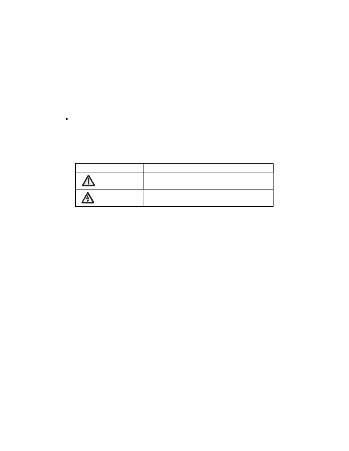
Safety Signs
The safety signs indicate the safety issues that should be conformed to in installation,
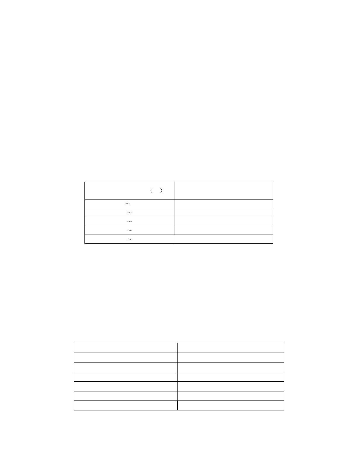
operation and maintenance. The safety signs are shown as following Table1.1-1
Table1.1-1 Safety Signs and Meanings
Safety Signs Meaning
Safety Notice
Electric Shock
1.2 Precautions
Before any operation of the equipment, please carefully read all the safety
instructions in this manual to avoid personal injury or equipment damage.
Shuangdeng Group bears no liability to the consequences incurred by violation of the
general safety operation requirement, or violation of the safety standards for designing,
manufacturing and using the equipment.
1. The battery pack has high voltage, so direct contact or indirect contact through wet
objects with any conducting cable may result in vital injury. The battery pack is
energy-storing equipment, so never short-circuit the battery pack during operation
and maintenance in any way.
2. Do not wear watch, hand chain, bracelet, ring and other conductive objects during
operation.
3. Only qualified and professional personnel are allowed to install, operate and maintain
the equipment.
4. Do use special tools.

Do use special tools, instead of common tools during electrical connections. In
addition, keep the tools in good insulation condition (e.g. wrap insulating tape around
the bare metal parts) before using them to avoid short circuit and personal injury
caused by tool contact with any live objects.
5. Using the batteries of the same model
Use batteries of the same model in the same set. Using different models in the same
set will damage the equipment.
6. Fire hazard
During battery installation, make sure to fix the connecting terminals of the
conducting wire tight, and keep the output terminals of the batteries clean. Otherwise,
it may lead to a high temperature of battery terminals and even to spark/fire.
7. Operation regulation
Before battery operation, read the safety precaution/instruction, and the operation
instructions, especially the battery interconnection instructions.
Substandard operation will cause danger. Prevent battery short circuit and
prevent battery electrolyte from flowing out. Overflowed electrolyte is a latent danger
and it will erode the metal object and circuit board, thus damaging the equipment and
causing short circuit of the circuit board.
8. The Operation Environment
The battery should be kept far away from fire, organic solution; avoid direct sunshine
and the temperature should be the same of the same set.
Chapter 2 Summary
Abstract
product sampling product
conveying and using ambient requirement parts denomination product specification and
main parameters.
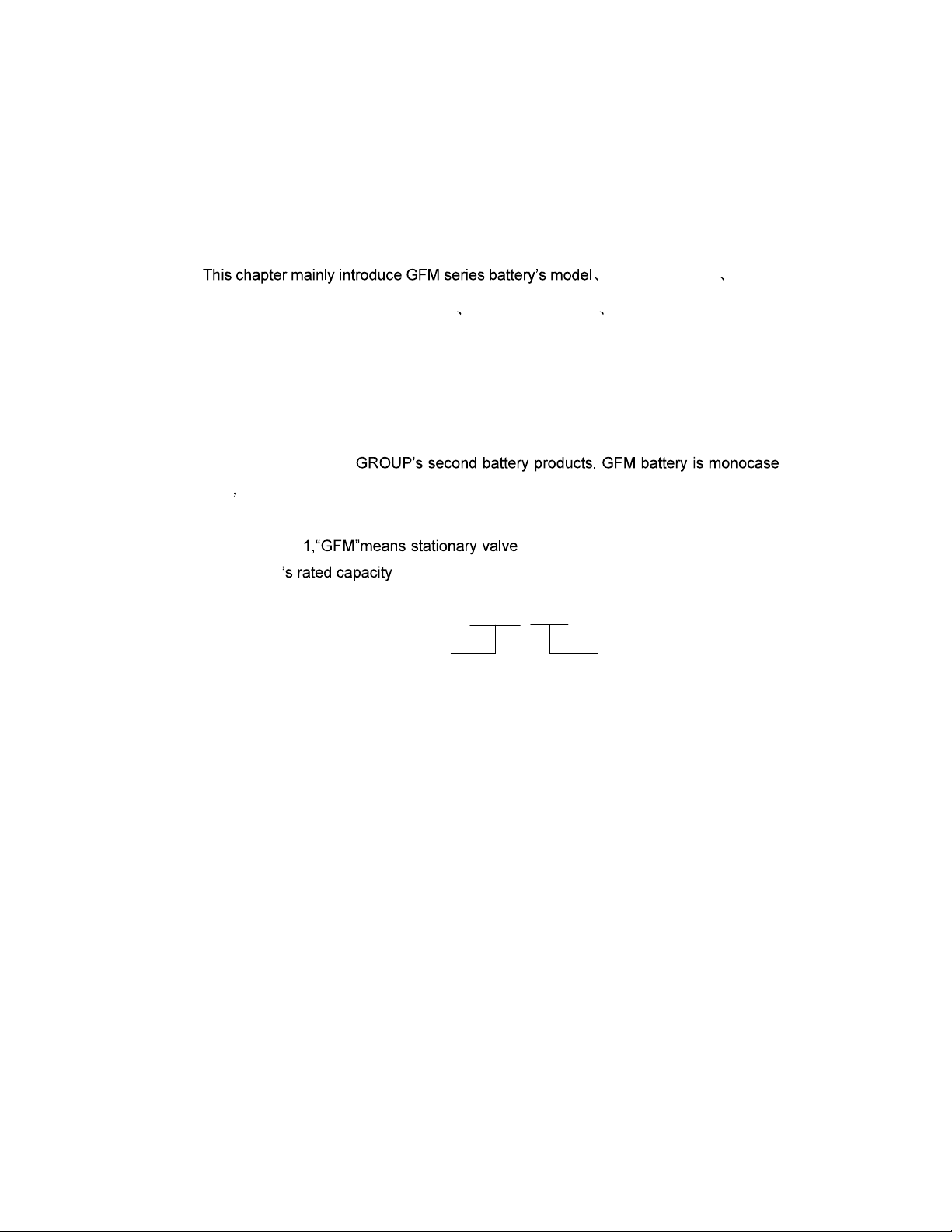
2.1 Model Introduction
GFM series valve-regulated lead-acid battery(following called GFM battery for short)
belong to SHUANGDENG
structure rated voltage per cell is 2V. Take GFM-500 for example, its mean as fig.2.1-1
showing.
In the fig.2.1- -regulated lead-acid battery, the figure
presents battery .
GFM-500
rated capacity C10
unit:Ah
valve-regulated
lead-acid battery
Fig.2.1-1 GFM-500 battery type and description
2.2 Sampling
Choosing batteries should consider use frequency, discharge current, discharge
time and so on. The capacity should be a bit larger to prevent battery from damage
caused by over-discharge or larger current discharge. Discharge current often be
controlled less than 0.1C10A.
2.3 Conveying
Terminal protection is well done, the coping of the battery cannot suffer the pressure,
safety valve cannot become flexible, and short circuit is prohibited when batteries are
conveyed. Batteries should stand up at the time of transporting and cannot set upside
down, roll, throw, bump, insolate or drench during conveying.
2.4 Storage
1. Batteries can be stored in the environment of 0-35°C before installation. The storage
time is usually 3-6months. Batteries should be charged if the storage time exceeds 6
months.
2. Batteries should be kept in the dry, clean and ventilated environment. They cannot be
kept in the environment of radiation, organic solvent and corrosive gas. They should
be kept away from fire and avoid sun irradiation.
3. Batteries should stand up, safety valve cannot become flexible and batteries without
package box cannot be overlapped.
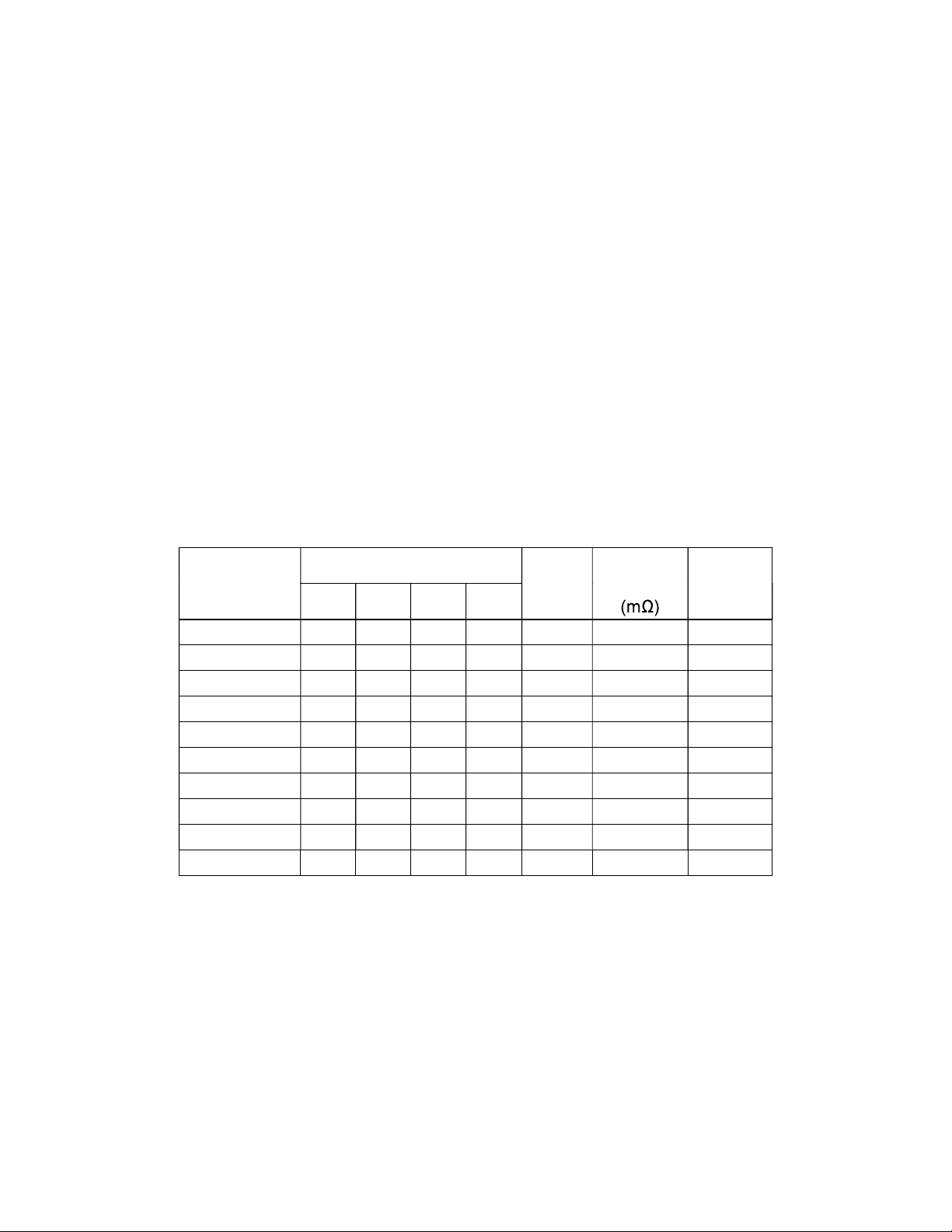
2.5 Dimension and Weight
Table2.5-1 Battery parameters
Type
Dimensions(mm) Weight
(Kg)
Internal
resistance
Terminal
L W H TH
GFM-200 90 181 346 365 12.5 0.90 M8
GFM-300 124 181 346 365 17.6 0.60 M8
GFM-400 158 181 346 365 23.0 0.51 M8
GFM-500 191 181 346 365 28.6 0.41 M8
GFM-600 225 181 346 365 33.2 0.39 M8
GFM-800 303 181 346 365 45.4 0.38 M8
GFM-1000 370 181 346 365 56.5 0.36 M8
GFM-1600 318 363 369 388 98.0 0.20 M8
GFM-2000 385 363 369 388 117.0 0.18 M8
GFM-3000 568 363 369 388 178.0 0.17 M8
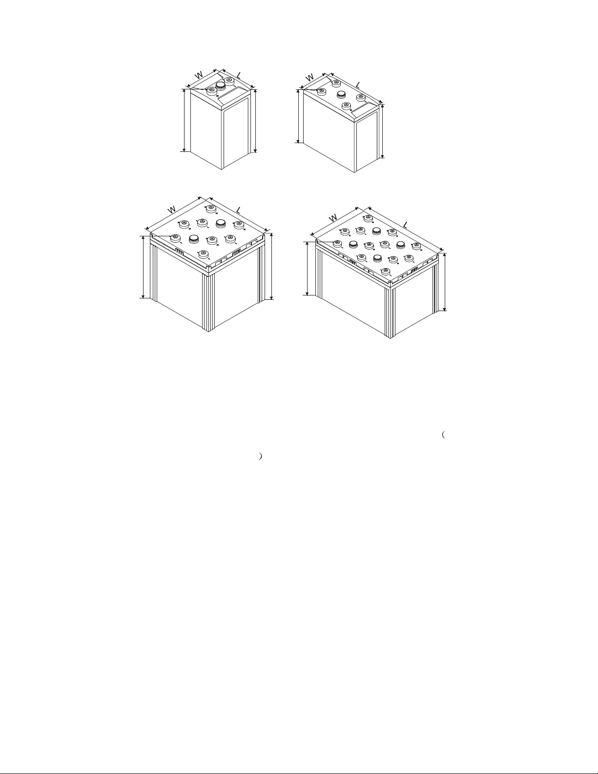
H
TH
H
TH
H
H
TH TH
Fig.2.5-1 Battery figuration
2.6 Battery Appearance and Each Part Denomination
Following is the appearance and each part denomination of GFM battery take
GFM-500 for example, as fig. 2.6-1
GFM-200~600 GFM-800~1000
GFM-3000
GFM-1600~2000
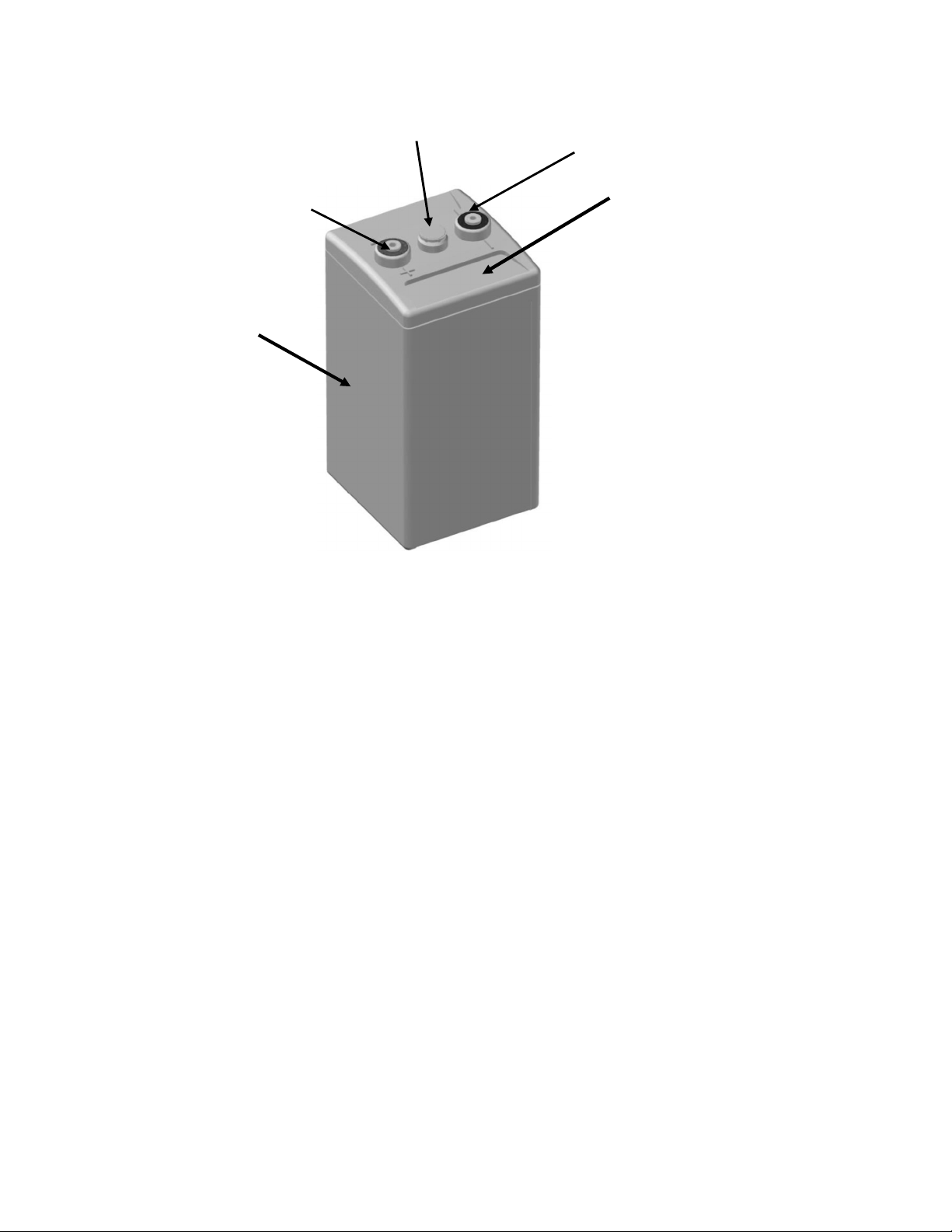
Fig.2.6-1 Battery figuration and accessories
2.7 Operation Environment and Precaution.
1. The battery servicing surroundings should be dry, clean and airy, without large
quantity of irradiation, infrared ray radiation, organic solvents and corrosive gas, and
avoided the direct sun shining. the temperature not exceed 35°C.
2. The ventilation hole of the heater or air-conditioner should not directly face the battery,
and the temperature difference of the each part of the battery should not be higher
than 3°C, and using the infrared ray thermometer to determine the each part
temperature of the battery is suggested.
3. The battery can be installed with the battery cabinet or shelf provided by the
manufacturer. If the battery is installed in the storied buildings, the load requirements
should be inquired from the construction department. The earthquake-preventing
supporting shelf which is fixed with ground foot bolt should be designed in order to
diffuse the stress in the district whose anti-earthquake intensity is more than 7
degree.
safety valve
positive terminal
container
negative terminal
cover

4. In order to avoid increasing the circuitry voltage decrease, the battery modules
should be near the load, and the cables, copper terminals and connecting wires
selected should be suitable. When the batteries are used by the way of
parallel-connection, the circuitry voltage decrease should be same to some extent to
the best of one's best ability, and the fuses should also be equipped in every battery
module.
5. The total voltage of the battery modules is comparatively higher, i.e., the danger of
electric shock exists. Therefore, the insulation tools should be used and the
protection gloves should be put on when installing or removing the cable, copper
terminals and connection wires etc.
6. Dirty contact or loosened connection will possibly lead to the temperature increase in
the part of the battery terminal, then spark will be produced, which will probably result
in fire. Thus, the cable, copper terminals, connection wires, and the battery terminals
should be kept clean and the connection should be fastened during the installation of
the battery. Single battery should be serially connected with stainless steel bolt,
copper terminals (connection wires and cables) electrodeposited with tin, and flat
gasket. And the bolt must be fastened (Wring moment is no less than 15N·m).
7. After the installation, carefully examine the total voltage, open circuit voltage per cell,
the polarity. Check to see if the supervising parameters in the switch power monitor
unit consist with the operation and maintenance manual (float charge voltage,
equalization charge voltage, equalization charging time and period, charge current
limit, equalization charge current turned to float charge, float charge current turned to
equalization charge current, temperature compensation value, the recovery voltage
of the battery and so on.).
8. Check to see if the switch power has equipped with the temperature sensor, which
should be installed in the center of the big side of the battery.
9. The resistance between the output terminal and the cabinet (shelf) should be
carefully checked in order to confirm the correctness of the installation and settings
after the battery system is installed.
10. The circuit switch should be disconnected, and the correctness mentioned in item
has been confirmed (it should be empathized that the positive terminals of the battery
should be connected with the positive counterpart of the charger, and negative to
negative) before the battery system is connected with the charger or load.
11. Never try to open the safety valve during operation
2.8 Check After Installation
After installation, check carefully and keep record, see Table 2.8-1 for the main
items.
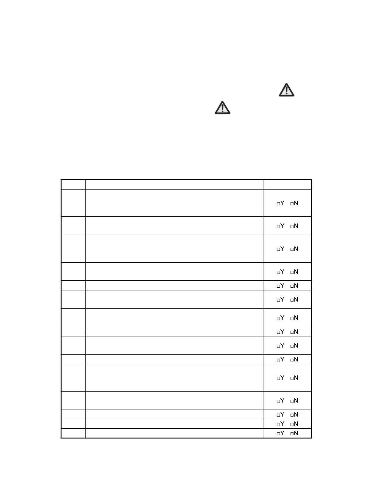
Table 2.8-1 The main items needed to be checked after installation
No. Items Results
1
The polarities are in right connection, the voltage of the battery
group between positive and negative output terminals are higher
than 48V
2
The voltage of each cell in the same battery group is between
2.1 and 2.2V.
3
If several battery groups are parallel connection, each output
positive terminals should be connected together and negative
terminals together.
4
The positive and negative output terminals of the battery group
should be connected with the counterparts of the charge device.
5 All of the bolts, nuts and screws are fastened tightly.
6 The rack has no deformation after installation, and its vertical
obliquity should be less than 5°.
7 No unnecessary connecting wires or tools etc. are left on the
batteries or racks.
8 The appearances of the batteries have no cracks or damages.
9The safety valve has been twisted tightly and has no
looseness or damage.
10 The ambient site of the batteries and rack is clean.
11
All of the parameters of the battery group, such as the
equalization charge and float charge currents, have been set
correctly.
12 The resistances between output terminals and the rack are
normal.
13 Other items need to be checked.
14
15

16
17
18

Chapter 3 Operation and Maintenance
Abstract
Operation and maintenance containing battery maintenance and precaution charge
method relationship of temperature and capacity relationship of temperature and cycle
life capacity checking switch power parameters setting usage requirement under
power-off condition maintenance periods and requirement.
This chapter introduces bout the operation and maintenance of GFM battery.
3.1 Operations
3.1.1 Precaution
1. Never short circuit the battery.
2. Charge before operation after long period storage.
3. No open of the safety valve.
4. Keep the battery clean.
5. Equalized charge the battery for long storage.
6. After emergency discharge, no continuous power supply without in time
equalized charge.
7. Never parallel the battery of different capacity.
8. No burning feel when touch the battery terminal or the connecting part.
3.1.2 Battery Charging
3.1.2.1 Float Charging
The float charging voltage of the battery is set as 2.23V/cell (the mean value
calculated from all of the battery voltages at 25°C), the maximum charging current is set
as 0.20C10A.The float and balancing charging voltages should be correspondingly
modified if the battery working environment temperature exceeds the range of 25°C, and
the modification voltage is Vmodification V25°C0.003/°C×(Tactual 25°C), i.e., if the
temperature increases by 1°C, then the float charging voltage should decrease by
3mV/cell; and if the temperature decreases by 1°C, then the float charging voltage should
increase by 3mV/cell.
3.1.2.2 Balancing Charging
Balancing charging voltage is usually set as 2.35V/cell (the mean value calculated
from all of the battery voltages at 25°C), and the maximum charging current is set as
0.2C10A, according to setting table to set Balancing charging time.
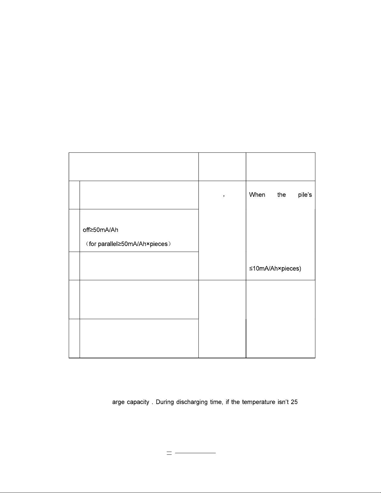
Table3.1-1 Balancing charging parameters
Balancing charging condition Balancing
charging time.
Conditions to exit the
balancing charging
1
Before operation and after installation
and debug of the battery
1~10h
The
idiographic
time according
to the
condition of
exiting
Balancing
charge
equalize charge
current lower than
10mA/Ah,
it switches
to float charge
automatically(for
parallel
2
The charge current after power
3
Balancing charge starts after battery
capacity checking
4
Balancing charge should start when the
float voltage lower than 2.18V/cell during
the using process
10h
When the balancing
charge time arrive 10h,
it switches to
float
charge
5
For net battery, it should execute periodic
balancing charge one time six months
commonly
3.1.3 Temperature Effects the Battery Capacity
Temperature effects the battery capacity. Usually, the higher the temperature, the
larger the disch °C, it
needs to convert the measured capacity C t to 25°C benchmark capacity C25 according to
the following formula.
1+K(t-25)
C
t
C
25
In the formula: t is the discharging ambient temperature, K is temperature coefficient.
In the 10hr capacity experiment, K=0.006/°C and 10hr capacity experiment, K=0.008/°C,
1hr capacity experiment, K=0.01/°C.
Float charge characteristic: Float charge voltage should choose the manufactory
recommendatory voltage value. And the float charge voltage value should make
correspond adjustment according to the ambient temperature. When the switch power
have temperature equalization function, but have no sensor or no temperature
auto-equalization function, VRLA battery float charge voltage with different temperature
should make correspond adjustment according to the following table.
Table3.1-2 Float charge voltage under different ambient temperature
Ambient temperature °C Float charge voltage(about
V±0.01V/cell)
0 10 2.28
11 15 2.26
16 25 2.23
26 30 2.22
31 40 2.19
3.1.4 Temperature Impact on the Battery Life
The battery has the longest service life and the best performance if the environment
temperature is kept at 24~25°C. When the temperature is lower than 25°C, the charging
efficiency and performance of the batteries will decrease. Vice versa, if the temperature is
higher than 25°C, the service life of the batteries will be shortened. The reference data are
listed below:
Table3.1-3 Effect of temperature on the battery service life
Battery mean temperature Service life decreasing rate (%)
25°C 0
30°C 30
35°C 50
40°C 66
45°C 75
50°C 83
The expected floating charging service life is around 15years. But if the actual mean

temperature of the batteries is around 35°C, then the expected floating charging service
life is only 7.5 years.
3.1.5 Capacity Determination
Balancing charging should be done before capacity determination. After balancing
charging changes into float charging, float charging current will be between 1~2 mA/Ah,
and if the float charging current is stable for about 2~3 hours, it shows that the battery
system has been fully charged. The capacity determination can be carried out only after
confirming that float charging has been continued for about 24h, then charging has been
stopped for 1h.
Table3.1-4 Capacity examination method
Discharge
rate
Discharge
current, A
Discharge single battery
final voltage V
Capacity determination
standard
10h 1.0I10 1.80 10
5h 1.6I10 1.80 10
3h 2.5I10 1.80 10
1h 5.5 I10 1.75 10
3.1.6 The Parameter Set of the Switch Power Supply
The control parameters of the switch power supply to the batteries should be set
according to the value of the load current. The parameters normally set are listed in Table.
Table3.1-5
The ratio of
load current
and I10
Stop the work of programmed
exchange machine, the final
discharge voltage of the single
battery V (the first
discharge-stopping)
Stop the work of signal exchange
transition the final discharge
voltage of the single battery, V
the second discharge-stopping
6/6 1.90 45.6V/48V system 1.88 45.0V/48V system
5/6 1.95 46.8V/48V system 1.93 46.3V/48V system
2/3 1.96 47.0V/48V system 1.94 46.5V/48V system
1/2 1.97 47.3V/48V system 1.95 46.8V/48V system
1/3 1.98 47.5V/48V system 1.96 47.0V/48V system
1/6 1.98 47.5V/48V system 1.96 47.0V/48V system
Note:
1. I10 means 10-hour rate discharge current in Table 6, its value is one-tenth of C10

which is the rated capacity of the battery. If the batteries are parallel connected, then
C10, the rated capacity is the sum of the rated capacity of all of the individual battery
paralleled (Batteries which have different rated capacities cannot be
parallel-connected).
2. If bad battery whose final discharge voltage is below 1.80V/cell when discharging it
with I10 after 5 hours occurs in the battery system, the very bad battery should be
displaced with a good one or restore its capacity as soon as possible.
3. The parameters listed in Table 6 and 7 are only suitable for the situation that the
discharge current is less than 0.1C10.
Table3.1-6 Switch power parameters setting
Item Parameter
Float charging voltage 2.23V/cell
Equalized charging voltage 2.35V/cell
Charge current limiting 0.20C10A
Upper voltage alarm threshold 57V 2.375V/ cell
Lower voltage alarm threshold 45V 1.875V/ cell
Temperature compensation coefficient of
battery -3mV/cell·°C
Battery over temperature 35°C
LVDS Deviation Voltage 44V
LVDS Reposition Voltage 47V
48V series pile replacement working
voltage
48V(avoiding battery deep discharge
resulted by the voltage rebound time after
time and continue work after arrivi
ng the
working voltage)
Equalized charge period
6 months usually for batteries in equipment
room
Periodical equalized charge time 10h
Precondition of float charge switching to
equalized charge
Equalized charge time with power cut 1 10h
Precondition to exit equalized charge
Capacity setting for battery diffluence According to battery capacity
Batteries connection Serial first, parallel next
Voltage difference between individual
batteries
50 mV for working mode
20 mV for open circuit mode

3.1.7 The Application Requirements for Power Supply Interruption
Time
1 Under the situation that the battery system has not been recharged after accident
discharge, and just at the very time, the power supply of the communication
station stops, often the battery system cannot be used to supply the power further.
If continue working, it could lead the battery life shorter because of the battery
deep discharge
2 If the accumulative discharge capacity reaches 50%~80% of the battery rated
capacity for one power supply interruption, the float charging time cannot be less
than 48h after balancing charging changes into float charging. If the accumulative
discharge capacity is less than 50% of the battery rated capacity for several
power supply interruption in one day, the float charging time cannot be less than
24h after balancing charging changes into float charging.
3 As far as the communication station, which has very good power supply
conditions, is concerned, protective C10 capacity discharge should be done every
6 months (depth of discharge is 50%), and the battery system should be
recharged in time.
4 Auxiliary power supply equipment, such as Oil Power Generator etc., should be
equipped for those communication stations in which frequent power interruption
exists and the power interruption time is very long. If discharge depth of the
battery system is above 80%, and the public power supply has not restore yet, Oil
Power Generator should be used to supply power to the communication station
equipments and recharge the battery at the same time.
3.2 Maintenance Period and Requirements
1 The newly installed battery system should be checked in the following aspects
when it is put into use --- whether or not the terminal voltage of every battery is
normal, charging and discharging current are stable, fastening parts are loose,
connecting parts and the battery terminals are being heated up by touch during
charge and discharge.

2 Individual battery terminal voltage should be determined every 3 months to judge
their evenness, good record should be done at the same time.
3 The maintenance person should periodically check that whether or not
connection bars are loose or move, vent valve is loose, single battery is damaged
and leaks, vent valve normally vents gas, battery is dry etc. And in site
maintenance should be done if problem occurs, and manufacturer should be
contacted to settle the problem if in site maintenance is very difficult.
4 The maintenance person should periodically determine the battery float charging
voltage, and check that whether or not there is individual battery which has very
high or low float charging voltage.
5 Check that whether or not there is difference between the total system voltage
and the voltage display of the Switch Power Supply. If difference exists, it should
be rectified.
6 Check that whether or not there is difference between the total system voltage
and the sum of all of the individual battery. If difference exists, the reason should
be checked out and then the difference should be corrected.
7 Record the relative electricity interruption and charging parameters in the Switch
Power Supply internal memory, and if necessary, it is strongly suggested that the
battery system be fully recharged.

Operation Instruction of Battery
Recharging
Shuangdeng Group Co.,Ltd
This manual suits for next models
10
Table of contents


