Siegen tools S0686.V2 User manual

Thank you for purchasing a Siegen product. Manufactured to a high standard this product will, if used according to these instructions
and properly maintained, give you years of trouble free performance.
1. SAFETY INSTRUCTIONS
IMPORTANT: PLEASE READ THESE INSTRUCTIONS CAREFULLY. NOTE THE SAFE OPERATIONAL REQUIREMENTS, WARNINGS & CAUTIONS.
USE THE PRODUCT CORRECTLY AND WITH CARE FOR THE PURPOSE FOR WHICH IT IS INTENDED. FAILURE TO DO SO MAY CAUSE
DAMAGE AND/OR PERSONAL INJURY, AND WILL INVALIDATE THE WARRANTY. PLEASE KEEP INSTRUCTIONS SAFE FOR FUTURE USE.
1.2 GENERAL SAFETY
Disconnect the drill from the mains power before changing accessories, servicing or performing any maintenance.
Maintain drill in good condition. Check moving parts and alignment, and keep drill bits sharp. If necessary use an authorised service agent.
Replace or repair damaged parts. Use recommended parts only. Unauthorised parts may be dangerous and will invalidate the warranty.
Wear approved safety eye protection with side shields, and a dust mask if drilling generates dust. Rubber gloves are recommended when
using outdoors, and safety gloves when drilling items such as steel, brickwork etc,
Remove ill fitting clothing. Remove ties, watches, rings, and other loose jewellery, and contain long hair.
Use drill in an adequate working area for its function, keep area clean, tidy and free from unrelated materials, and ensure adequate lighting.
Prevent body contact with grounded surfaces to avoid electric shock i.e. pipes, radiators, ranges, refrigerators etc.
Evaluate your working area before using the drill i.e. ceiling, floors and enclosures may contain hidden electrical wires or water piping.
Maintain correct balance and footing. DO NOT over-reach and ensure the floor is not slippery and wear non-slip shoes.
The supplementary handle grip should always be attached for use.
Keep children and unauthorised persons away from the working area.
Secure unsecured workpiece with a clamp, vice or other adequate holding device. DO NOT hold unsecured work in your hand.
Avoid unintentional starting, and ensure the lock-on button is disengaged before use.
DO NOT use the drill for a task it is not designed to perform.
DO NOT operate drill where there are flammable liquids or gasses.
DO NOT get the drill wet or use in damp or wet locations.
DO NOT operate the drill if any parts are missing or the drill is damaged, as this may cause failure and/or possible personal injury.
DO NOT operate the drill when you are tired or under the influence of alcohol, drugs or intoxicating medication.
DO NOT carry the drill with your finger on the power switch, or carry by the power cord, or leave the drill running whilst unattended.
When not in use, switch drill off, remove plug from power supply, clean the drill and store in safe, dry, childproof location. ,
1.1. ELECTRICAL SAFETY
WARNING! It is the responsibility of the owner and the operator to read, understand and comply with the following:
You must check all electrical products, before use, to ensure that they are safe. You must inspect power cables, plugs, sockets and any other
connectors for wear or damage. You must ensure that the risk of electric shock is minimised by the installation of appropriate safety devices. A
Residual Current Circuit Breaker (RCCB) should be incorporated in the main distribution board. We also recommend that a Residual Current
Device (RCD) is used. It is particularly important to use an RCD with portable products that are plugged into a supply which is not protected
by an RCCB. If in any doubt consult a qualified electrician. You may obtain a Residual Current Device by contacting your Siegen dealer.
You must also read and understand the following instructions concerning electrical safety.
1.1.1. The Electricity at Work Act 1989 requires all portable electrical appliances, if used on business premises, to be tested by a qualified
electrician, using a Portable Appliance Tester (PAT), at least once a year.
1.1.2. The Health & Safety at Work Act 1974 makes owners of electrical appliances responsible for the safe condition of those appliances
and the safety of the appliance operators. If in any doubt about electrical safety, contact a qualified electrician.
1.1.3. Ensure that the insulation on all cables and on the appliance is safe before connecting it to the power supply. See 1.1.1. and 1.1.2.
and use a Portable Appliance Tester.
1.1.4. Ensure that cables are always protected against short circuit and overload.
1.1.5. Regularly inspect power supply cables and plugs for wear or damage and check all
connections to ensure that none is loose.
1.1.6. Important: Ensure that the voltage marked on the appliance matches the power supply
to be used and that the plug is fitted with the correct fuse - see fuse rating at right.
1.1.7. DO NOT pull or carry the appliance by the power cable.
1.1.8. DO NOT pull the plug from the socket by the cable.
1.1.9. DO NOT use worn or damaged cables, plugs or connectors. Immediately have any faulty
item repaired or replaced by a qualified electrician. When an ASTA/BS approved UK
3 pin plug is damaged, cut the cable just above the plug and dispose of the plug safely.
Fit a new plug according to the following instructions (UK only).
a) Connect the GREEN/YELLOW earth wire to the earth terminal ‘E’.
b) Connect the BROWN live wire to the live terminal ‘L’.
c) Connect the BLUE neutral wire to the neutral terminal ‘N’.
d) After wiring, check that there are no bare wires, that all wires have been correctly connected, that the cable outer
insulation extends beyond the cable restraint and that the restraint is tight.
Double insulated products, which are always marked with this symbol , are fitted with live (brown) and neutral (blue) wires only.
To rewire, connect the wires as indicated above - DO NOT connect either wire to the earth terminal.
1.1.10. Products which require more than 13 amps are supplied without a plug. In this case you must contact a qualified electrician to ensure
that a suitably rated supply is available. We recommend that you discuss the installation of an industrial round pin plug and socket
with your electrician.
1.1.11. If an extension reel is used it should be fully unwound before connection. A reel with an RCD fitted is preferred since any appliance
plugged into it will be protected. The cable core section is important and should be at least 1.5mm², but to be absolutely sure that the
capacity of the reel is suitable for this product and for others which may be used in the other output sockets, we recommend the use
of 2.5mm² section cable. If extension reel is to be used outdoors, ensure it is marked for outdoor use.
INSTRUCTION MANUAL
ELECTRIC HAMMER DRILL
MODEL NO.
S0686.V2
Original Language Version S0686.V2 Issue: 1 - 23/10/12
© Jack Sealey Ltd
RECOMMENDED FUSE
RATING: 5 amp

3. OPERATING INSTRUCTIONS
Input power:.......................... 230V - 50Hz
Motor: ....................................750W
No load speed: .........................0-2900rpm
Chuck capacity: ............................ 13mm
Hammer action: .......................0-43500bpm
Drilling capacity for steel: .................... 10mm
Drilling capacity for masonry: ................. 13mm
Drilling capacity for wood: ................... 20mm
Weight: ...................................2.4kg
Sound pressure level: .......................101dB
Sound power level: .........................90dB.A
Vibration level:(Under load)............... 13.422m/s²
Vibration level (No load) .................... 1.5m/s²
1. Trigger lock button
2. Trigger
3. Variable speed knob
4. Forward/Reverse switch
5. Drill/Impact switch
6. Chuck
7. Depth gauge
8. Side handle
9. Chuck key
3.1. PREPARING DRILL FOR USE.
3.1.1. Ensure the drill is switched off and unplugged from the mains power supply.
3.1.2. Fitting the side handle. (Fig.1.8) Fit side handle grip by placing the handle assembly over the chuck and onto the machine neck.
Secure by rotating the handle clockwise until it is tight and the handle can no longer be moved. To ensure a good grip in all
circumstances, the angle of the handle may be changed by rotating the handle grip anticlockwise until the handle assembly is loose.
Rotate the handle to the desired angle and retighten.
3.1.3 Fitting the depth gauge. (Fig.1.7) To fit the depth gauge loosen the side handle and pass the gauge through the handle
clamp to the required depth. Rotate the handle to the required angle. As the handle is tightened the depth gauge will also be gripped
firmly.
3.2. DRILL CONTROLS
3.2.1. ON/OFF Variable speed trigger. The drill has a variable speed control On/Off trigger (Fig.1.2) speed increases as the trigger is
depressed. Adjacent to the trigger is a button that can be used to lock the trigger in the ‘ON’ position for continuous drilling.
3.2.2 Trigger lock. (Fig.1.1) To lock ‘ON’, depress the trigger, push in and hold the button then release the trigger. Release the
lock-on button and the drill will continue running.
3.2.3 To release the lock, depress the trigger and the lock releases.
3.2.4 Power failure. If you have the lock-on feature engaged during use and the drill becomes disconnected from the power supply,
make sure that the lock is released, before reconnecting to the power supply.
WARNING! Before connecting the drill to a power supply, ensure it is not in the lock-on position as this may result in
damage and personal injury. Depress the trigger to ensure release. DO NOT use the lock-on facility for jobs where the drill
may need to be stopped suddenly. ,
3.2.5. Maximum speed setting control. The variable speed trigger has a small rotating knob incorporated into it (Figs.1.3 & 2.3) which can
be used to control the maximum speed of the drill. When the knob is set to the maximum or +setting the trigger can be fully
depressed allowing the drill to turn at its maximum speed. As the knob is turned towards the minimum or - setting, the movement of
the trigger is restricted so that the drill will turn at a lower pre-set speed when the trigger is fully depressed. This facility is useful when
working with materials that should be drilled at a constant, lower speed.
3.2.6. The required speed will depend on the material and task in hand. The following may be used as a general guide.
a) Low speeds are recommended for hard materials, i.e. stone, ceramic, concrete, high tensile steel, and tasks such as starting
holes without centre punch, driving screws, mixing paint etc.
b) Medium speeds are suitable for plastics and laminates.
c) High speeds recommended for soft materials such as wood, aluminium, copper, bronze and brass.
CAUTION: DO NOT run the drill at low to medium speeds for extended periods of time as this may cause drill to overheat.
To cool drill, run it without a load, at full speed, for a few seconds.
3.2.7 Direction of rotation. Select either forward or reverse rotation using the lever mounted directly above the trigger (Figs.1.4 & 2.4).
Select reverse by moving the lever towards the ‘L’ symbol and forward by moving the lever adjacent to the ’R’ symbol and the trigger
lock button.
CAUTION: Do not attempt to change direction of rotation whilst the drill is still running.
3.2.8 Selection of hammer action / drilling. When using a masonry drill bit, the hammer action can be used to assist penetration into
concrete, stone and masonry. The hammer action selector is a large sliding ‘switch’ situated on top of the drill (Fig.3).
To select hammer action slide the selector to the left so that it is adjacent to the hammer symbol moulded on the side of the case.
To disable the hammer action slide the switch in the other direction to be adjacent to the drill symbol moulded on the casing.
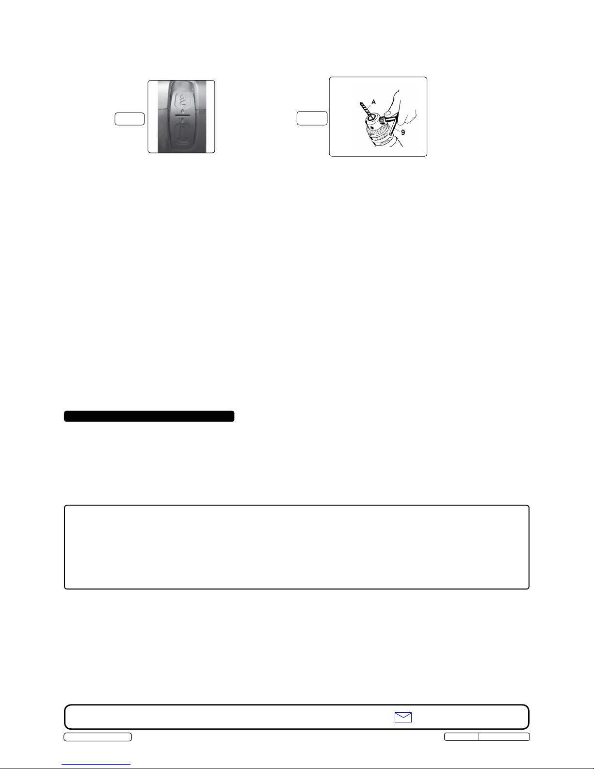
3.3. DRILL OR TOOL BIT FITTING.
WARNING! Unplug from the mains power supply before placing bit into chuck.
Adjust the chuck jaws to a point where the opening is slightly larger than the drill/tool bit (Fig.4.A) to be used. Also raise the front of
the drill slightly to stop the bit from falling out of the chuck jaws. Insert the drill/tool bit into the chuck as far as it will go. Place the
chuck key in one of the chuck holes and tighten the chuck fully by turning the chuck key clockwise (Fig 4.9).
2. TECHNICAL SPECIFICATION
Original Language Version S0686.V2 Issue: 1 - 23/10/12
Fig.2
© Jack Sealey Ltd
Fig.1
4.1. Changing the drill chuck.
To remove the drill chuck, open the chuck fully. Locate the internal screw head and undo by turning the screw CLOCKWISE (left handed
thread). Stop the chuck from moving by securing the nut at the base of the chuck with a spanner. To replace the chuck reverse the
above procedure.
4.2. Cleaning the drill.
Keep the drill ventilation slots clean and free from obstructions. If available, blow compressed air into the vents to clear any internal
dust (safety goggles must be worn when undertaking this process). Keep the outer case of the drill clean and free from grease.
DO NOT wash with water, or use solvents or abrasives. ,
3.5. STANDARD DRILLING INSTRUCTIONS.
WARNING!Ensure you wear approved safety goggles and any other safety item required for the job. Remove the chuck key
before using the drill, and ensure the trigger button lock is not locked in position which would result in accidental starting of
the drill. Also ensure that all other safety requirements in chapter 1 are followed.
Ensure drill is unplugged from the mains power supply.
3.5.1. If the material to be drilled is free standing it should be secured in a vice or with clamps to keep it from turning as the drill bit rotates.
3.5.2. When drilling metals, use a light oil on the drill bit to keep it from overheating. Oil will prolong life of the drill bit and improve the drilling
action.
3.5.3. For hard smooth surfaces use a centre punch to mark desired hole location. This will prevent bit from slipping as drilling is started.
3.5.4. A pilot hole may be necessary to assist the final drill size through the workpiece. Lock a pilot drill (smaller size drill than the finished
hole size) into the chuck. Follow steps 3.5.5 to 3.5.7. below and drill a pilot hole in the middle of the centre punch mark where final
hole is to be drilled. Insert the final sized bit. Hold drill firmly and place the bit at the entrance of the pilot hole and depress the trigger.
3.5.5. Plug drill into mains power supply.
3.5.6. Hold tool firmly and place the drill bit tip to the point to be drilled.
3.5.7. Depress the trigger to start drill. Move the drill bit into the workpiece, applying only enough pressure to keep the bit cutting.
DO NOT force or apply side pressure, which will elongate the hole.
WARNING! Be prepared for drill binding or break through. When these situations occur the drill has a tendency to grab and
kick in the opposite direction and could cause loss of control. If you are not prepared, this loss of control could result in
damage and/or personal injury.
3.5.8. If the drill bit jams in the workpiece or if the drill stalls, release the trigger switch immediately. Remove the drill bit from the workpiece
and determine the reason for jamming, before recommencing drilling.
3.5.9. For continuous operation, depress the trigger lock (see 3.2.2).
3.5.10. The depth gauge may be used to pre-determine the depth of hole (see 3.1.3 and 3.4).
3.5.11. After working for a lengthy period of time at low speed setting, run drill for a few seconds with no load, at high speed.
WARNING! Drill bits become very hot during use. Allow to cool or hold with a cloth for removal.
3.5.12. When work is complete, unplug from the mains power supply, remove the drill bit / tool bit from the chuck, clean drill, clean and if
necessary sharpen the tool bit, and store drill in a safe, dry childproof location. ,
3.4. DEPTH STOP GAUGE.
Ensure the workpiece has a flat surface and is wide enough for the gauge to butt up against it when the required depth has been reached.
Measure back from the tip of the drill bit to the point at which the drill must stop. Release clamp/handle and extend the depth gauge to the
point at which you wish to stop drill penetrating further and retighten the handle/clamp. Once the drill has reached the correct depth, the
gauge will butt up against the workpiece and stop further inward progress.
4. MAINTENANCE
Fig.4
Risk of Hand Arm Vibration Injury.
The S0686.V2 Electric Hammer Drill, when operated in accordance with these instructions and tested in accordance with: BS EN ISO 28927-5:2009 results in
the following vibration emission declared in accordance with: BS EN 12096:1996
Measured vibration emission value:.............13.4m/s² Uncertainty: .............5.37m/s²
These values are suitable for comparison with emission levels of other tools that have been subject to the same test.
This tool may cause hand-arm vibration syndrome if its use is inadequately managed.
Recommended Measures to reduce risk of hand-arm vibration syndrome:
This tool should not be used by an individual regularly for more than 34 minutes in any 8 hour period.
This duration of use should be reduced if the individual is exposed to hand-arm vibration from other sources.
NOTE: It is our policy to continually improve products and as such we reserve the right to alter data, specifications and component parts without prior notice.
IMPORTANT: No liability is accepted for incorrect use of this equipment. WARRANTY: Guarantee 12 months from purchase date, proof of which will be required for any claim.
Sole UK Distributor, Siegen Tools, Sealey Group,
Kempson Way, Suffolk Business Park, Bury St. Edmunds, Suffolk, IP32 7AR [email protected]
Original Language Version S0686 V.2 Issue 1 23/10/12
email
© Jack Sealey Ltd
↑↓
Fig.3
Table of contents
Other Siegen tools Drill manuals


