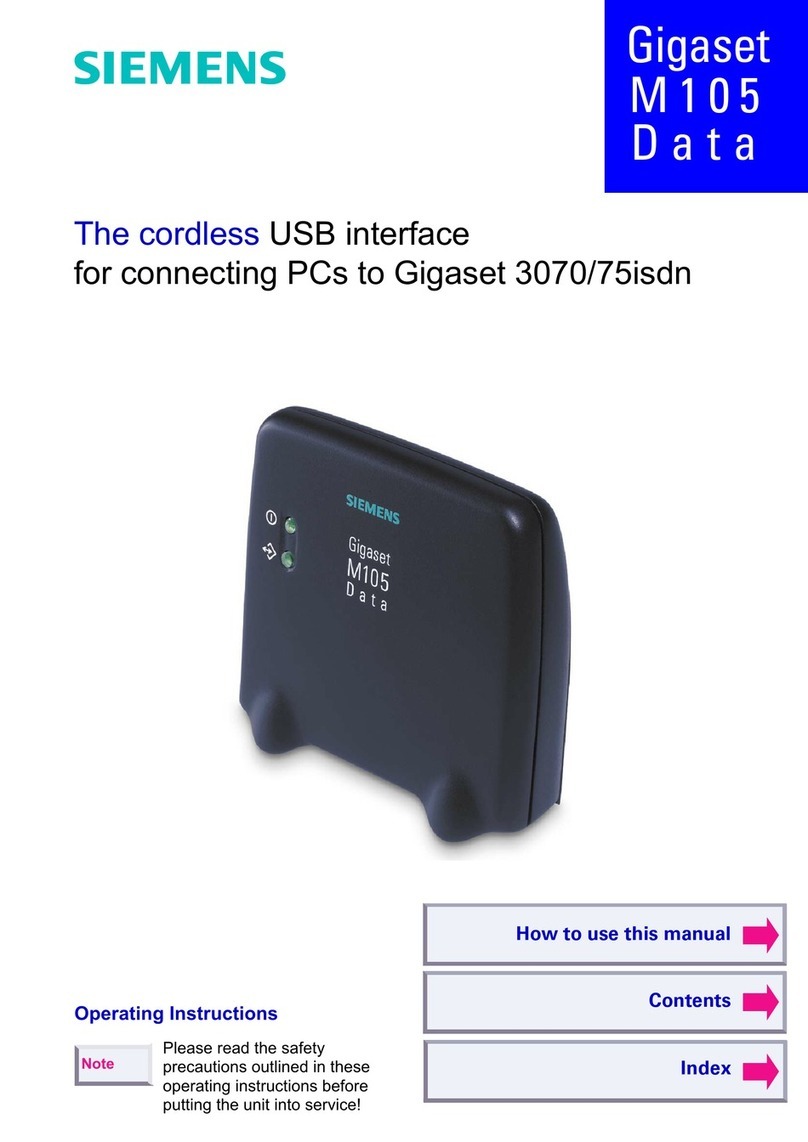
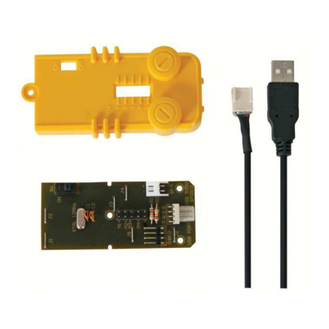
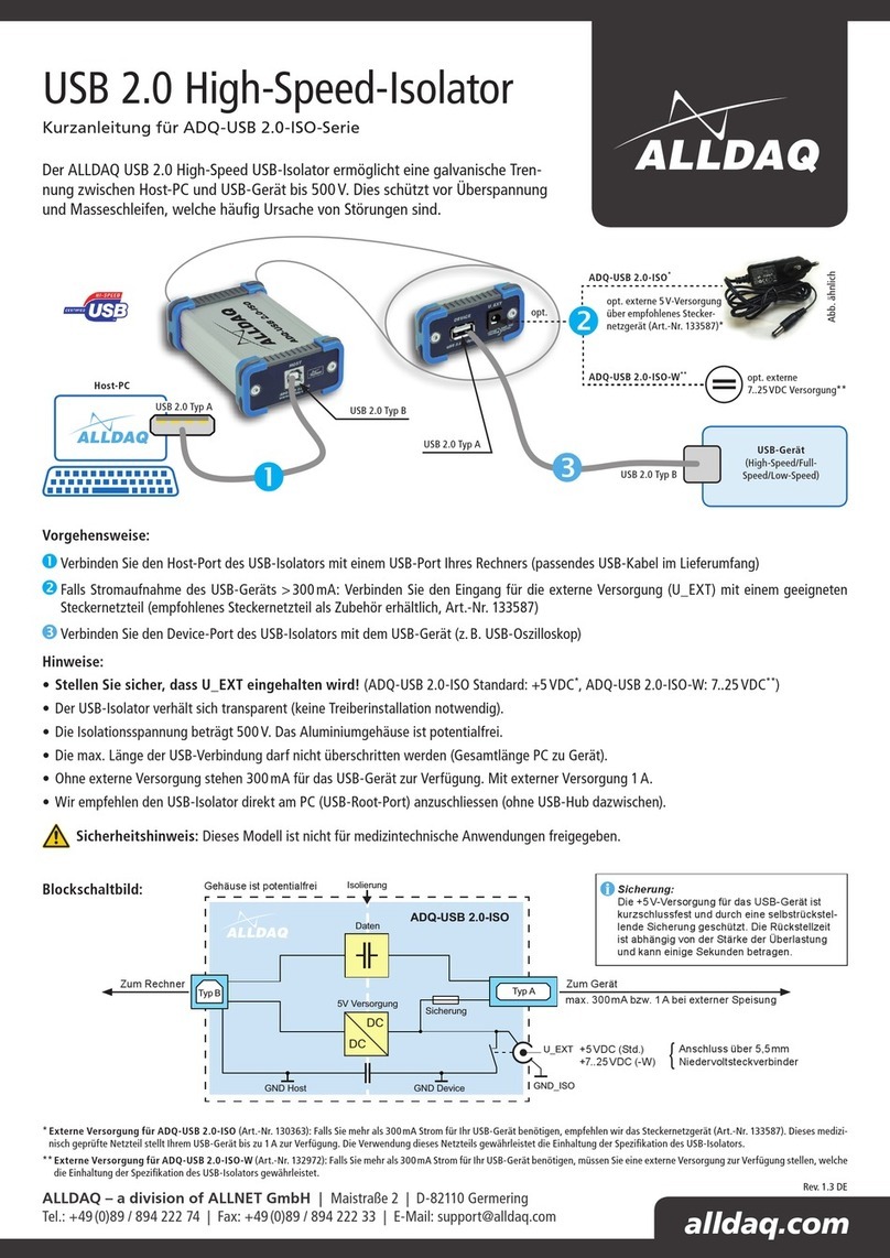
Siemens Gigaset M105 Data User manual

2
+RZWRXVHWKLVPDQXDO
The following controls are available in Acrobat Reader or in the context menu (right mouse
button):
Click here when you see this hand.
Click here to jump to this section.
Contents
Introduction . . . . . . . . . . . . . . . . . . . . . . . . . . . . . . . . . . . . . . . . . . . . . . . . . . . . . . . . . .9
What is a Gigaset M101 Data? . . . . . . . . . . . . . . . . . . . . . . . . . . . . . . . . . . . . . . . . . . . .9
Meaning of "local adapter" and "remote adapter" . . . . . . . . . . . . . . . . . . . . . . . . . . . . .10
Meaning of "base" and "portable part" . . . . . . . . . . . . . . . . . . . . . . . . . . . . . . . . . . . . . .10
Click here to jump to this section.
11. It may be useful to switch the operating mode from "AT commands
(PC)" to one of the two other operating modes. This setting con-
cerns the protocol on the serial interface, especially the speed ad-
justment.
"Setting the operating mode" on page 12
.
12. Close the program with "OK".
In the event of errors or for further information, see
"Configuration
program options" on page 10
.
A
Clickheretojump
to the table of
contents.
Click here to jump to
the index.
Back
Jumpbacktothelast
position shown.

A
Contents
2
Back
Contents
How to use this manual . . . . . . . . . . . . . . . . . . . . . . . . . . . . . . . . . . . . . . . . . . . . . . . . . . . . . . . . 2
Overview . . . . . . . . . . . . . . . . . . . . . . . . . . . . . . . . . . . . . . . . . . . . . . . . . . . . . . . . . . . . . . . . . . . 1
Introduction . . . . . . . . . . . . . . . . . . . . . . . . . . . . . . . . . . . . . . . . . . . . . . . . . . . . . . . . . . . . . . . . 4
What is a Gigaset M105 Data? . . . . . . . . . . . . . . . . . . . . . . . . . . . . . . . . . . . . . . . . . . . . . . . . . . 4
Meaning of "local adapter" and "remote adapter" . . . . . . . . . . . . . . . . . . . . . . . . . . . . . . . . . . . . 4
Meaning of "base" and "portable part" . . . . . . . . . . . . . . . . . . . . . . . . . . . . . . . . . . . . . . . . . . . . . 5
Contents of the package . . . . . . . . . . . . . . . . . . . . . . . . . . . . . . . . . . . . . . . . . . . . . . . . . . . . . . . 5
Installation . . . . . . . . . . . . . . . . . . . . . . . . . . . . . . . . . . . . . . . . . . . . . . . . . . . . . . . . . . . . . . . . . . 6
Confi
g
uration . . . . . . . . . . . . . . . . . . . . . . . . . . . . . . . . . . . . . . . . . . . . . . . . . . . . . . . . . . . . . . . 7
Registering Gigaset M105 Data at Gigaset 3070isdn/3075isdn . . . . . . . . . . . . . . . . . . . . . . . . . 7
Registering Gigaset M105 Data at Gigaset M105 Data . . . . . . . . . . . . . . . . . . . . . . . . . . . . . . . 8
Registering Gigaset M105 Data at Gigaset M101 Data . . . . . . . . . . . . . . . . . . . . . . . . . . . . . . . 9
Confi
g
uration
p
ro
g
ram o
p
tions . . . . . . . . . . . . . . . . . . . . . . . . . . . . . . . . . . . . . . . . . . . . . . . 10
General . . . . . . . . . . . . . . . . . . . . . . . . . . . . . . . . . . . . . . . . . . . . . . . . . . . . . . . . . . . . . . . . . . . 10
Starting the configuration program . . . . . . . . . . . . . . . . . . . . . . . . . . . . . . . . . . . . . . . . . . . . . . 10
"Connection" tab . . . . . . . . . . . . . . . . . . . . . . . . . . . . . . . . . . . . . . . . . . . . . . . . . . . . . . . . . . . . 11
Upper section: connecting to the PC . . . . . . . . . . . . . . . . . . . . . . . . . . . . . . . . . . . . . . . . . . . . . 11
Lower section: DECT connection . . . . . . . . . . . . . . . . . . . . . . . . . . . . . . . . . . . . . . . . . . . . . . . 11
"Operating mode" tab . . . . . . . . . . . . . . . . . . . . . . . . . . . . . . . . . . . . . . . . . . . . . . . . . . . . . . . . 12
Setting the operating mode . . . . . . . . . . . . . . . . . . . . . . . . . . . . . . . . . . . . . . . . . . . . . . . . . . . . 12
Special settings for "Direct connection" mode . . . . . . . . . . . . . . . . . . . . . . . . . . . . . . . . . . . . 13
"Local adapter" tab . . . . . . . . . . . . . . . . . . . . . . . . . . . . . . . . . . . . . . . . . . . . . . . . . . . . . . . . . . 15
Changing the name . . . . . . . . . . . . . . . . . . . . . . . . . . . . . . . . . . . . . . . . . . . . . . . . . . . . . . . . . . 15
Change adapter type . . . . . . . . . . . . . . . . . . . . . . . . . . . . . . . . . . . . . . . . . . . . . . . . . . . . . . . . . 15
Registering a portable part . . . . . . . . . . . . . . . . . . . . . . . . . . . . . . . . . . . . . . . . . . . . . . . . . . . . 16
De-registering a portable part . . . . . . . . . . . . . . . . . . . . . . . . . . . . . . . . . . . . . . . . . . . . . . . . . . 17
Automatic enabling . . . . . . . . . . . . . . . . . . . . . . . . . . . . . . . . . . . . . . . . . . . . . . . . . . . . . . . . . . 17
"Remote adapter" tab . . . . . . . . . . . . . . . . . . . . . . . . . . . . . . . . . . . . . . . . . . . . . . . . . . . . . . . . 18
Changing the name . . . . . . . . . . . . . . . . . . . . . . . . . . . . . . . . . . . . . . . . . . . . . . . . . . . . . . . . . . 19
Chan
g
e PIN ... . . . . . . . . . . . . . . . . . . . . . . . . . . . . . . . . . . . . . . . . . . . . . . . . . . . . . . . . . . . . . 19
LEDs . . . . . . . . . . . . . . . . . . . . . . . . . . . . . . . . . . . . . . . . . . . . . . . . . . . . . . . . . . . . . . . . . . . . . 20
LED 1: Gigaset M105 Data status . . . . . . . . . . . . . . . . . . . . . . . . . . . . . . . . . . . . . . . . . . . . . . . 20
LED 2: data transfer . . . . . . . . . . . . . . . . . . . . . . . . . . . . . . . . . . . . . . . . . . . . . . . . . . . . . . . . . 20
Notes on installation and operation . . . . . . . . . . . . . . . . . . . . . . . . . . . . . . . . . . . . . . . . . . . . . . 21
Place of installation . . . . . . . . . . . . . . . . . . . . . . . . . . . . . . . . . . . . . . . . . . . . . . . . . . . . . . . . . . 21
Temperature and ambient conditions . . . . . . . . . . . . . . . . . . . . . . . . . . . . . . . . . . . . . . . . . . . . 21
Why set an operating mode? Technical background . . . . . . . . . . . . . . . . . . . . . . . . . . . . . . . . 22
Special features when connecting two Gigaset M105 or M101 Data units . . . . . . . . . . . . . . . . 22
Notes on the COM interface . . . . . . . . . . . . . . . . . . . . . . . . . . . . . . . . . . . . . . . . . . . . . . . . . . . 22

A
Contents
3
Back
Ti
p
s&tricks, settin
g
s . . . . . . . . . . . . . . . . . . . . . . . . . . . . . . . . . . . . . . . . . . . . . . . . . . . . . . . . 24
Access to different V.24 terminals from a laptop: . . . . . . . . . . . . . . . . . . . . . . . . . . . . . . . . . . . 24
Sequential access from multiple computers to a terminal: . . . . . . . . . . . . . . . . . . . . . . . . . . . . 25
PC-PC direct cable connection: via RS232/V.24 interface . . . . . . . . . . . . . . . . . . . . . . . . . . . . 26
Setting the direct connection to the correct baud rate . . . . . . . . . . . . . . . . . . . . . . . . . . . . . . . . 26
Sharing files . . . . . . . . . . . . . . . . . . . . . . . . . . . . . . . . . . . . . . . . . . . . . . . . . . . . . . . . . . . . . . . . 33
Examples of PC-PC direct cable connection problems . . . . . . . . . . . . . . . . . . . . . . . . . . . . . . . 34
What ha
pp
ens if... . . . . . . . . . . . . . . . . . . . . . . . . . . . . . . . . . . . . . . . . . . . . . . . . . . . . . . . . . . 35
Support . . . . . . . . . . . . . . . . . . . . . . . . . . . . . . . . . . . . . . . . . . . . . . . . . . . . . . . . . . . . . . . . . . . 36
Updates and news on the Internet . . . . . . . . . . . . . . . . . . . . . . . . . . . . . . . . . . . . . . . . . . . . . . . 36
Notes on sending faxes directly from the PC . . . . . . . . . . . . . . . . . . . . . . . . . . . . . . . . . . . . . . 36
Problems with application programs . . . . . . . . . . . . . . . . . . . . . . . . . . . . . . . . . . . . . . . . . . . . . 37
Technical data . . . . . . . . . . . . . . . . . . . . . . . . . . . . . . . . . . . . . . . . . . . . . . . . . . . . . . . . . . . . . . 39
Safety precautions . . . . . . . . . . . . . . . . . . . . . . . . . . . . . . . . . . . . . . . . . . . . . . . . . . . . . . . . . . . 40
Index . . . . . . . . . . . . . . . . . . . . . . . . . . . . . . . . . . . . . . . . . . . . . . . . . . . . . . . . . . . . . . . . . . . . . 41

Introduction
A4
Back
Introduction
What is a Gi
g
aset M105 Data?
Your Gi
g
aset M105 Data is a cordless USB interface for operation at the
Gi
g
aset 3070/75isdn base station, at a second Gi
g
aset M105 Data or at
a Gi
g
aset M101 Data (V.24 interface).
You can thus use this cordless USB port for
y
our PC as an alternative to
the inte
g
rated USB port at the Gi
g
aset 3070/3075isdn base station.
Gi
g
aset M105 Data features of a confi
g
uration pro
g
ram.
Meanin
g
of "local ada
p
ter" and "remote ada
p
ter"
These names are used for identif
y
in
g
the adapters and their role in data
communication. The "Local adapter" is the adapter that performs all con-
fi
g
urations (also for the "remote adapter"). This means that the Gi
g
aset
M105 Data setup routine does not have to be installed on the second PC
in the case of a direct cable connection.
A Gi
g
aset M105 Data unit is powered via the USB port but op-
erates like a COM interface with re
g
ard to data.
The USB cable cannot be extended!
Remote adapter
Local adapter
Radio link

Introduction
A5
Back
Meanin
g
of "base" and "
p
ortable
p
art"
This is an assi
g
nment in the DECT connection (Base FP = Fixed Part,
PP=PortablePart) andrefers exclusivel
y
to theair interface. A baseis the
same as a base station in Gi
g
aset telephon
y
. Here, portable part is the
same as handset. This is defined, for example, throu
g
h the re
g
istration
option. Onl
y
one Gi
g
aset M105 Data "Portable part" can have an active
connection to a Gi
g
aset 3070/75isdn or a Gi
g
aset M101/M105 Data
"Base". Up to 6 portable parts or up to 6 bases can be re
g
istered (multi-
link operation).
Contents of the
p
acka
g
e
1. Gi
g
aset M105 Data
2. CD-ROM with the installation pro
g
ram and operatin
g
instructions
3. Installation brochure
4. USB cable
The Gi
g
aset Repeater cannot be used to extend the radio
ran
g
e for Gi
g
aset M105 Data, althou
g
h it can for Gi
g
aset hand-
sets.

Introduction
A6
Back
Installation
Prerequisites for installation
For installation,
y
ou need:
zan IBM-compatible PC with the followin
g
confi
g
uration:
– Windows 98 operatin
g
s
y
stem
– approx. 5 MB free hard disk memor
y
– 1 free USB slot activated in the PC’s BIOS
– CD-ROM drive,
zthe CD-ROM containin
g
the installation pro
g
ram
Installing
1. Switch on the PC.
2. Insert the CD in the CD-ROM drive.
3. Connect the USB port on the Gi
g
aset M105 Data to the USB interface on
y
our PCs b
y
means of the USB cable provided.
The hardware assistant appears on the screen.
4. If prompted to enter the source for the driver, enter the CD director
y
, for
Windows 98 = win98.
Confirm all displa
y
s with OK or Next. A new virtual COM port is now con-
fi
g
ured.
5. Click Install in the open Gigaset M 100 Data Setup.
The installation pro
g
ram starts up.

Configuration
A7
Back
Confi
g
uration
The purpose of confi
g
uration is to re
g
ister the Gi
g
aset M105 Data unit at
a Gi
g
aset 3070/3075isdn base station, at a second Gi
g
aset M105 Data
or at a Gi
g
aset M101 Data. You can onl
y
perform confi
g
uration with the
confi
g
uration pro
g
ram.
Re
g
isterin
g
Gi
g
aset M105 Data at Gi
g
aset 3070isdn/
3075isdn
Proceed as follows:
1. Install Gi
g
aset M105 Data.
2. Switch Gi
g
aset 3070/3075isdn to re
g
istration mode (press LED).
3. Start the Gi
g
aset M105 Data confi
g
uration pro
g
ram.
4. Select the Local adapter tab.
5. Click the Register button and enter the base station PIN.
6. Find a re
g
istration location and click OK. The re
g
istration procedure
starts and the messa
g
e "If the required base is ready for registration,
the local adapter logs on. Check that the base is ready for registra-
tion." appears on the screen.
The two devices are automaticall
y
s
y
nchronised. There is now one entr
y
in the Registered bases list.
7. Close the pro
g
ram with OK.
In the event of errors or for more information, see
"Configuration pro-
gram options" on page 10
.

Configuration
A8
Back
Re
g
isterin
g
Gi
g
aset M105 Data at Gi
g
aset M105 Data
Proceed as follows:
1. Connect both Gi
g
aset M105 Data units to a PC.
2. Start the Set Gigaset pro
g
ram at both PCs.
3. Select the Local adapter tab at both PCs.
4. Chan
g
e the t
y
pe of Gi
g
aset M105 Data at one of the PCs from "Portable
part" to "Base".
5. Click the Register button at both PCs.
At the PC connected to the "Base" t
y
pe Gi
g
aset M105 Data, a LED flash-
es in sequence to si
g
nal that the unit is read
y
for re
g
istration. The confi
g
-
uration pro
g
ram is now complete.
Further confi
g
uration is now performed exclusivel
y
at the PC connected
to the "Portable part" t
y
pe Gi
g
aset M105 Data. Enter the PIN at this PC.
This is "0000" b
y
default.
6. Click OK. The re
g
istration operation starts and the messa
g
e "If the re-
quired base is ready for registration, the local adapter logs on.
Check that the base is ready for registration." appears on the screen.
The two devices are automaticall
y
s
y
nchronised. There is now an entr
y
in the Registered bases list.
7. Give the local station a suitable name, e.
g
."PC".
8. Select the Remote adapter tab and
g
ive this also a name, e.
g
. "Gi
g
aset
3075isdn". The re
g
istered portable part also appears in the window here.
9. It ma
y
be useful to switch the operatin
g
mode from "AT commands (PC)"
to one of the other operatin
g
modes. This settin
g
concerns the protocol
on the serial interface, in particular the speed adjustment. For more infor-
mation, seer
"Setting the operating mode" on page 12
.
10. Close the pro
g
ram with OK.
In the event of errors or for further information, see
"Configuration pro-
gram options" on page 10
.

Configuration
A9
Back
Re
g
isterin
g
Gi
g
aset M105 Data at Gi
g
aset M101 Data
Proceed as follows:
1. If the M101 is not alread
y
in the default status, please ensure that the
M101 is operatin
g
as a "Base". Please refer to the confi
g
uration pro
g
ram
for the t
y
pe displa
y
and the switch options.
2. Press and hold down the black button on the Gi
g
aset M101 Data (Base).
After approx. 10 seconds, the LEDs indicate that the s
y
stem is read
y
for
re
g
istration b
y
flashin
g
in sequence.
3. Start the Set Gigaset pro
g
ram at the PC connected to the Gi
g
aset M105
Data unit.
4. Select the Local adapter tab. The t
y
pe is "Portable part".
5. Click the Register button and enter the PIN.
6. Click OK. The re
g
istration procedure starts and the messa
g
e "If the re-
quired base is ready for registration, the local adapter logs on.
Check that the base is ready for registration." appears on the screen.
The two devices are automaticall
y
s
y
nchronised. An entr
y
now appears
in the Registered bases list.
7. Assi
g
n a suitable name to the local adapter, e.
g
."PC".
8. Open the Remote adapter tab and assi
g
n a name to it, e.
g
. "Gi
g
aset
3075isdn". The re
g
istered portable part now also appears in this window.
9. It ma
y
be useful to switch the operatin
g
mode from "AT commands (PC)"
to one of the other operatin
g
modes. This settin
g
concerns the protocol
on the serial interface, especiall
y
the speed adjustment. For more infor-
mation, see
"Setting the operating mode" on page 12
.
10. Close the pro
g
ram with OK.
In the event of errors or for further information, see
"Configuration pro-
gram options" on page 10
.

Configuration program options
A10
Back
Confi
g
uration
p
ro
g
ram o
p
tions
General
You will not need the majorit
y
of confi
g
uration options for the simple im-
plementation of a Gi
g
asetM105 Data unit downstream of a Gi
g
aset 3070/
3075.
Startin
g
the confi
g
uration
p
ro
g
ram
Under Start, select Programs followed b
y
Gigaset M100 Data
and fi-
nall
y
Set Gigaset.
The confi
g
uration pro
g
ram offers a dialo
g
box entitled Properties of Gi-
gaset M101 Data which contains the four tabs Connect, Operating
mode, Local adapter und Remote adapter.
A number of special fields are also provided for special inputs.

Configuration program options
A11
Back
"Connection" tab
Upper section: connecting to the PC
You can set the virtual COM port at which the local adapter is connected
in the upper section of the tab.
We recommend leavin
g
the option No automatic detection at program
start-up deactivated (as shown). The pro
g
ram then checks the existin
g
COM ports and determines where the adapter is connected. Manual in-
terface selection is onl
y
recommended if there is more than one Gi
g
aset
M105 Data unit connected to the PC.
As soon as the pro
g
ram finds an adapter or identifies the manuall
y
se-
lected interface, it sends it the confi
g
uration command via the control
lines. This action switches the adapter to confi
g
uration status. This is in-
dicated b
y
the Status: displa
y
in the dialo
g
box. Gi
g
aset M105 Data can
onl
y
be confi
g
ured under these conditions. Your Gi
g
aset M105 Data will
automaticall
y
switchtheadapter backtooperatin
g
statusat the endofthe
pro
g
ram.
Lower section: DECT connection
This section indicates whether a radio connection exists and if so, to
which Remote adapter. It also indicates the qualit
y
of the connection.
A Remote adapter must be re
g
istered before it can be selected here.

Configuration program options
A12
Back
"O
p
eratin
g
mode" tab
Important:
The "Operating mode" tab is not active if the re
g
istered Remote adapter
is a Gi
g
aset 3070/75isdn. In this case, no settin
g
s can be made in this
tab.
If one of the adapters is set to "AT commands (PC)" or "AVM compatible
(PC)", the other adapter must switch to the correspondin
g
operatin
g
mode "AT commands (device)" or "AVM compatible (device)". If one
adapter is switched to "Direct connection", the other adapter must also
be switched to this mode. The appropriate switches are performed auto-
maticall
y
if
y
ou select an operatin
g
mode for a Gi
g
aset M105 Data unit.
Setting the operating mode
Open the Operating mode tab and select one of the five modes:
The three connection t
y
pes are used for different purposes:
Direct connection The permanent transmission parameters for the vir-
tual COM port are manuall
y
set at the computer
without automatic baud rate or data format reco
g
ni-
tion. This is alwa
y
s useful if the device at the Re-
mote adapter does not support baud rate or data
format reco
g
nition as performed b
y
conventional
modems, e.
g
. in the case of a second PC.
AT commands
(PC)Automatic reco
g
nition of the transmission parame-
ters based on the data from the PC at the local
adapter.

Configuration program options
A13
Back
Special settings for "Direct connection" mode
InDirect connectionmode, thefields in thelower section ofthe dialo
g
box
are activated:
y
ou can set the transmission parameters for the virtual
COM port at the PC.
Use the default settin
g
s if
y
ou do not want to chan
g
e an
y
other parame-
ters.In theevent of malfunctions,reducethe speed inthe Bits persecond
field. Set
y
our communication software likewise to this value.
In the case of chan
g
es, onl
y
permitted values are accepted in the individ-
ual fields, even for manual inputs.
Dataflow control list
You can set whether the data transmission is controlled b
y
the hardware
or software. The usual settin
g
is
Hardware (RTS/CTS)
. RTS means "Re-
quest To Send" and CTS means "Clear To Send".

Configuration program options
A14
Back
fLocal flow control check box
Localflow control normall
y
does not have tobe activatedexcept when op-
eratin
g
low-memor
y
V.24 terminals (in connection with Gi
g
aset M101
Data). Activatin
g
local flow control can help in the event of data transmis-
sion problems (e.
g
. sendin
g
faxes, operatin
g
a serial printer).
When local flow control is active, the Gi
g
aset M105 Data unit connected
to the V.24 terminal immediatel
y
stops outputtin
g
data in the direction of
the terminal when a STOP si
g
nal is received and saves this data in its
own memor
y
. This ensures that the PC onl
y
sends data that can be proc-
essed b
y
the transmission route (saved). If local flow control is not acti-
vated, the V.24 terminal’s STOP si
g
nal is transferred to the PC. Durin
g
this time (less than 10 ms), the PC continues to send data. All ofthis data
is output b
y
the Gi
g
aset M101 Data unit in the direction of the V.24 termi-
nal. If the terminal does not have sufficient memor
y
to receive this data,
the data is lost.

Configuration program options
A15
Back
"Local ada
p
ter" tab
Changing the name
The purpose of adapter names is to provide a rapid overview. The local
adapter must be called "PC". The remote adapters should, if possible, be
named after the peripheral device connected, e.
g
. "3070/3075isdn" or
"Modem".
Adapter names can be chan
g
ed b
y
enterin
g
or chan
g
in
g
a name in the
Name field. Names can contain letters and di
g
its as well as blanks. The
name must not contain more than 20 characters.
Change adapter type
Normall
y
, a portable part is operated at the PC and the base station is op-
erated at the peripheral device. Other constellations, however, are possi-
ble in which both adapters are connected to a PC in order, for example,
to create a cordless data connection between two PCs. In this case, the
adapter t
y
pe of one of Gi
g
aset M105 Data units must be Base while the
adapter t
y
pe of the other must be a Base. Or
y
ou can implement more
than one remote adapter in order to control a second PC or the modem
alternatel
y
. It ma
y
also be necessar
y
here to chan
g
e the adapter t
y
pe at
one of the Gi
g
aset M105 Data units.
zEnsure that the correct Gi
g
aset M105 Data is connected at the PC.
zSelect Change adapter type. The chan
g
e is performed in the back-
g
round. You can see that it has been performed when the information
in the Adapter type: line chan
g
es.

Configuration program options
A16
Back
Registering a portable part
Both adapters are powered. The Gi
g
aset M105 Data unit is connected to
the PC; start the "Set Gigaset" pro
g
ram.
Select the Local adapter tab.
The followin
g
dialo
g
box appears:
Up to six re
g
istered devices can be entered in the Registered adapter
window. Dependin
g
on the adapter t
y
pe of the local adapter, Registered
adapter or Registered bases is displa
y
ed.
Select a re
g
istration location and click Register.
The followin
g
window appears when the local adapter is a Base (factor
y
settin
g
is "Portable part"):

Configuration program options
A17
Back
Enter the PIN and click OK
.
The portable part now searches for the base station and automaticall
y
re
g
isters at it.
If re
g
istration is not possible (base station not in re
g
istration mode or not
powered, incorrect PIN), the s
y
stem will indicate the necessar
y
steps for
resolvin
g
this problem.
De-registering a portable part
Select the adapter in the window and click Unregister.
Automatic enabling
The automatic enablin
g
feature is not available with Gi
g
aset3070/75isdn.
The data connection is automaticall
y
enabled as soon as usa
g
e stops.
The "Permit automatic enabling:" feature eliminates the need to enable
the data connection manuall
y
. If the V.24 interface is not used for a set
len
g
th of time (no activit
y
on the V.24 interface and control line DTR = 0),
then this is automaticall
y
enabled and can be automaticall
y
seized b
y
an-
other portable part. See "Remote adapter" tab on pa
g
e18.
If
y
ou permit automatic enablin
g
,
y
ou must also define an enablin
g
time.

Configuration program options
A18
Back
"Remote ada
p
ter" tab
This tab is used for confi
g
urin
g
the Remote adapter that is not connected
to the PC. Re
g
istration must be performed first so that the two Gi
g
aset
M105 Data units can communicate.
The Remote adapter tab is onl
y
available after re
g
istration on
the Local adapter tab.
Other manuals for Gigaset M105 Data
1
Table of contents
Other Siemens USB Interface manuals