Sigicom INFRA C12 User manual

Manual
Copyright © Sigicom AB 2019 Art.no. ML089-04212-0En
INFRA C12
Wireless Triaxial Vibration Monitor
Art no. 080-04212-0 (2G and 3G versions)
(3G version is marked on front- and right-side of unit)
Manual ver. H
Valid for firmware version 1.5.2
Read instructions on safety, electrical equipment waste and battery recycling before
operating this product.
Copyright © Sigicom AB 2019
2
Developed and manufactured by:
Sigicom AB
Glasfibergatan 8, floor 3
SE – 125 45 Älvsjö, Sweden
Support: support@sigicom.com
IMPORTANT SAFETY
INSTRUCTIONS
– read this before use.
Operating conditions and limitations:
• This equipment is designed for outdoor use and wet locations
but must not be submerged.
• Safe temperature range is -30 to +50 ºC
(-22 to +122 ºF).
• Range for full functionality is -20 to +50 ºC
(-4 to +122 ºF).
• This equipment includes radio transmitters. Its antennas should
be installed away from operator or third-party persons to be safe.
Recommended minimum distance is 1meter (3 ft.).
• Only use antennas provided or recommended by Sigicom.
• Before installing the equipment, make sure there are no
restrictions for the use of radio transmitters at the intended site.
• Do not use the equipment in presence of flammable fumes or
gases, or in explosive atmospheres.

Copyright © Sigicom AB 2019
3
IMPORTANT SAFETY
INSTRUCTIONS
– read this before use.
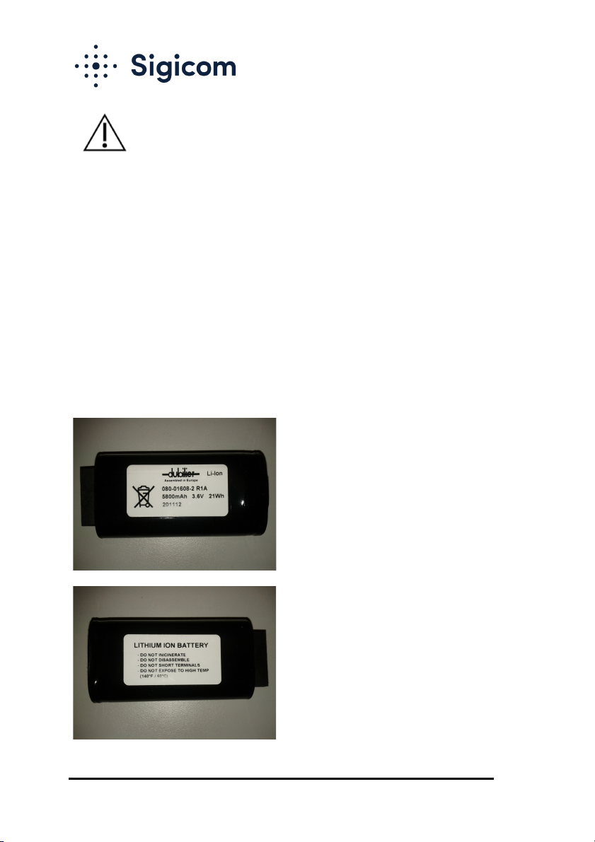
Li-Ion batteries:
• Only use batteries and chargers provided or recommended by
Sigicom, see Accessories
• Under no circumstances, a charger which can supply more than
4.2V or 1.3A may be used for loose batteries.
• A charger connected to the C12 must not be able to supply more
than 15V and 1A.
• Replacement of the batteries may only be done by persons who
have read this manual very carefully and registered this to
Sigicom AB (see the registration template in Appendix F.
Operator’s Registration Template)
• Never keep the batteries at temperatures above 50ºC (122ºF).
• Transportation of Lithium Ion batteries by aircraft is regulated by
UN and IATA, see Appendix C.
• Transportation by road or railway is exempt from dangerous
goods transportation regulations. Still, handling and packaging
needs to be handled carefully, otherwise severe injury may
happen.
• If damaged, the batteries should be individually embedded into
sand in a sturdy plastic drum container during transport. It is also
recommended to affix a “Lithium Ion” label with an additional
text: ‘Damaged batteries’ on the package.
• Never incinerate, disassemble or expose the batteries for water.
• If the terminals of the battery are shorted, the battery may
become very hot and permanently damaged.
• A worn-out battery, a battery with cracks or with signs of
swelling or leakage, should be replaced immediately.
Note! Damaged or worn out batteries are prohibited in air freight.
• Prepare your warehouse and charging sites according to
Appendix D and Appendix E.
• Charge the batteries in a well-ventilated room, away from
flammable material, open fire and electric sparks.
• If the battery case is penetrated, it may burn with open fire.
Copyright © Sigicom AB 2019
4
IMPORTANT SAFETY
INSTRUCTIONS
– read this before use.
Removal of Li-Ion batteries from the equipment:
• Remove the lid at the left side of the equipment using a Torx T20
driver.
• Turn the lock lever to one side to release the first battery and pull
out the battery.
• Turn the lock lever to the other side to release the second battery
and pull out the battery.
• The lock lever must be reset in its middle position for the lid to
fit.
For information about transportation rules for equipment and
batteries, see Appendix C.

Copyright © Sigicom AB 2019
5
IMPORTANT SAFETY
INSTRUCTIONS
– read this before use.
US customers:
• Contains FCC ID QIPMC55i (2G version)
• Contains FCC ID N7NHL8548 (3G version)
Canadian customers:
• Contains IC 267W-MC55i (2G version)
• Contains IC 2417C-HL8548 (3G version)
Copyright © Sigicom AB 2019
6
This equipment falls under the Waste Electrical and Electronic Equipment
Directive (WEEE directive) 2012/19/EU, category 9: monitoring and
control instruments:
• Scrapped equipment should be sent back to the manufacturer of
the equipment (Sigicom AB) for proper handling according to the
WEEE directive.
• Sigicom uses a certified local partner for recycling of scrapped
equipment.
The batteries used in this equipment falls under the Battery Directive
2006/66/EC:
• When the equipment is sold to customers in the European Union,
except Sweden, the customer is the importer of the battery. The
customer needs to follow the regulations in its own country or
send the battery/equipment back to the manufacturer of the
equipment (Sigicom AB) for proper disposal.
• Swedish customers are allowed to recycle the battery in the
national battery collection system.
• Users outside the EU may send the batteries back to the
manufacturer of the equipment (Sigicom AB) for proper disposal.

Copyright © Sigicom AB 2019
7
Table of Contents
1. Introduction ......................................................................................... 9
1.1. INFRA Monitoring System ....................................................... 9
1.2. INFRA C12 Triaxial Vibration Monitor ................................... 9
1.3. Automatic Data Transfer through GSM/Internet .................... 10
1.4. Unpacking and Parts Identification ......................................... 10
2. The Enclosure ................................................................................... 11
2.1. Buttons .................................................................................... 11
2.2. LEDs ....................................................................................... 12
2.2.1. Comm LED (yellow/orange) .............................................. 12
2.2.2. Check LED (white or red) .................................................. 13
2.2.3. Reg LED (green) ................................................................. 13
2.3. Antennas .................................................................................. 14
2.4. Battery Module ........................................................................ 14
2.5. Solar Panel .............................................................................. 15
2.6. External Power Port ................................................................ 15
2.7. USB Connector (Mini-B Type) ............................................... 16
2.8. CompactFlash .......................................................................... 16
2.9. SIM Card ................................................................................. 18
3. Measuring Parts of the System ......................................................... 19
3.1. Measuring Hardware ............................................................... 19
3.1.1. Vibration Sensor ................................................................. 19
3.1.2. Analog Electronics .............................................................. 19
3.1.3. Analog-Digital Conversion ................................................. 19
3.1.4. Digital Signal Processing .................................................... 19
3.2. Measuring Logic ..................................................................... 20
3.2.1. Measurement Standards ...................................................... 20
3.2.2. Interval Measurements ........................................................ 20
3.2.3. Frequency Detection, Weighting and Trigger filter ............ 21
3.2.4. Transient Recording ............................................................ 22
3.2.5. Overload Handling .............................................................. 22
3.3. File Types ................................................................................ 23
3.3.1. Event Files (.log) ................................................................. 24
3.3.2. Interval Files (.interval) ...................................................... 24
3.3.3. Transient Files (.transient) .................................................. 25
3.4. Data Storage on CompactFlash ............................................... 26
4. Configuration and Installation .......................................................... 27
4.1. Configurations and Settings .................................................... 27
4.1.1. Data Server Connection Schedule ...................................... 27

Copyright © Sigicom AB 2019
8
4.1.2. GSM Settings ...................................................................... 27
4.1.3. Running without Data Transfer .......................................... 28
4.1.4. Data Server Settings ............................................................ 28
4.1.5. Project ID Text .................................................................... 28
4.1.6. Node ID Text ...................................................................... 28
4.1.7. SMS Settings ....................................................................... 29
4.1.8. INFRA Net Messages ......................................................... 30
4.1.9. INFRA Net Live ................................................................. 30
4.1.10. Factory Default Settings ..................................................... 31
4.2. Mounting ................................................................................. 31
5. Operation .......................................................................................... 32
5.1. Startup ..................................................................................... 32
5.2. Start Monitoring ...................................................................... 32
5.2.1. Sensor Test .......................................................................... 33
5.3. Stop Monitoring ...................................................................... 34
5.4. Data Server Connection .......................................................... 34
5.4.1. Automatic Data Server Connection .................................... 34
5.4.2. Manual Data Server Connection ......................................... 35
5.5. Instrument Power Off .............................................................. 35
5.6. Power Lost .............................................................................. 36
5.7. Remote Control ....................................................................... 36
6. Other Functions ................................................................................. 38
6.1. Inhibit Sending of Transient Files ........................................... 38
6.2. Time Synchronization through Internet .................................. 38
6.3. Daylight Saving Time ............................................................. 39
6.4. Skip File Archive .................................................................... 40
7. Technical Specifications ................................................................... 41
8. Accessories ....................................................................................... 42
9. Maintenance and Calibration ............................................................ 43
10. Contact and Support .......................................................................... 44
Battery Voltage Limits ....................................................... 45
Configuration File Reference List ...................................... 46
Li-Ion battery transport. ..................................................... 47
Safe Handling of Li-Ion Batteries ...................................... 48
In Case of Li-Ion Battery Fire ............................................ 49
Operator’s Registration Template ...................................... 50
Measurement Standards ..................................................... 51
Tables of Weighted Standards ........................................... 66
The use of Weighting Standard .......................................... 71
The use of US standard ISEE Seismograph (S51 and S52)75

Copyright © Sigicom AB 2019
9
1. Introduction
1.1. INFRA Monitoring System
The traditional INFRA system is based on a model with a central data
logger unit and different types of digital sensor nodes connected to the
data logger via a digital bus cable.
The data logger collects measuring data from the nodes, stores these data
as files on a CompactFlash and also sends these files over GSM/Internet
to a data server. The data files can then be used by applications such as
INFRA Net for presentation of reports etc.
The original concept with separate data logger and sensor nodes should be
kept in mind to fully understand the various aspects of the C12 instrument
as described in this manual.
1.2. INFRA C12 Triaxial Vibration Monitor
The INFRA C12 is a complete wireless vibration monitor measuring in
three directions. It consists of a tri-axial vibration sensor, together with
measuring electronics, digital signal processing, CompactFlash, quad band
GSM/GPRS modem, antenna and batteries.
The vibration sensor is divided in three nodes named:
• C12V (vertical)
• C12L (longitudinal)
• C12T (transversal)
all with separate serial numbers.
Generated data files are sent in the same file format as used by the
traditional INFRA system, and they can be used with ordinary INFRA
applications such as INFRA Net.
The INFRA C12 concept presupposes the presence of INFRA Net to
control the instrument, because C12 has no graphical display or menu
interface.

Copyright © Sigicom AB 2019
10
1.3. Automatic Data Transfer through GSM/Internet
All files, which are stored on the CompactFlash, are normally sent to a
data server through GSM/Internet when:
• Monitoring is started or stopped.
• A trigger event has occurred.
• An error event has occurred, e.g. low battery.
• Manual connection is performed by the operator.
• Time has reached a scheduled time for data server connection.
The files are sent to a data server available through the Internet, where
INFRA Net can access them.
Note! 3G version can be identified by the product label and is 2G
compatible. It does not communicate faster than the 2G version.
1.4. Unpacking and Parts Identification
Your INFRA C12 Triaxial Vibration Monitor has been shipped in
protective packaging. Please keep this and use it when transporting your
equipment.
Verify the package content with the following list:
• C12 Triaxial Vibration Monitor instrument.
• Foam (which protects your C12 from shock during
transportation).
• CompactFlash inserted in the C12.
• Two (2) batteries, either inserted in C12 or separate.
Note! Because of shipping regulations, batteries may be
charged below 30% state of charge at delivery.
• Calibration document.
Any damage or shortage should be reported immediately to Sigicom.
Keep record of the instrument’s serial number. You will be asked to give
this number in any C12 related communication you may have with
Sigicom.

Copyright © Sigicom AB 2019
11
2. The Enclosure
The enclosure is milled out of solid aluminum and is very robust. It has
one horizontal hole for mounting on the wall.
The box has two lids which are sealed with O-rings. The top lid gives
access to the CompactFlash and SIM card for the GSM function. The left
side lid gives access to the batteries and the USB connector.
There is also a hole at the bottom of the enclosure, where a wire lock may
be attached to lock the C12 to a fix and solid structure for theft
prevention. The wire lock is sold separately.
Note! C12 is not intended to be submerged in water.
2.1. Buttons
There are two buttons on the right-hand side of C12, the upper (B1) and
the lower (B2). For more information of operation of the buttons see
chapter 5 Operation.
• B1 short Power ON (see section 5.1).
• B2 long Power OFF (see section 5.5).
• B1+B2 long Toggle monitoring mode
(see sections 5.2 and 5.3).
• B1 long Data server connection
(see section 5.4.2).
Note! ‘Long’ indicates that the button must be pressed for at least three
seconds.

Copyright © Sigicom AB 2019
12
2.2. LEDs
There are three LEDs (light-emitting diodes) on the top of C12.
• Comm (yellow/orange) Communication activity.
• Check (white or red) Status/operation.
• Reg (green) Monitoring activity.
Note! The white color of the Check LED is often not pure white but looks
more like light purple.
2.2.1. Comm LED (yellow/orange)
• Flashes with 50% duty cycle when the GSM modem is starting
up.
• Will be lit continuously or in a more asymmetric way when
communication is active.
• After a GSM connection is completed, this LED will flash
synchronously with the Check LED (white)to show the GSM
signal strength for one minute (if not aborted by a new
connection). There are three levels of strength, which is
represented by a number of flashes every two seconds:
o 3 works in most situations (RSSI > 30%).
o 2 may fail in urban areas with high
buildings (20% < RSSI < 30%).
o 1 will fail in many situations (RSSI < 20%).
• If the communication fails completely the Comm LED will flash
synchronously with the Check LED (red). It is then
recommended to check the last ‘.log’ files on the memory card.
Also read the file ‘/config/modemlog.txt’, where all
communication with the GSM modem of the last failed
connection is logged. If you can’t solve the problem after this,
contact Sigicom support.
Note!
On units equipped with a 3G modem, the RSSI value is more
unreliable. RSSI values lower than the 20-30% mentioned above
may still be enough to send data. !

Copyright © Sigicom AB 2019
13
2.2.2. Check LED (white or red)
Shows the battery status by flashing five times every two seconds or every
eight seconds if in monitoring mode, following:
o 3 white flashes very good.
o 2 white flashes good.
o 1 white flash OK.
o 1 red flash bad.
o 2 red flashes very bad.
Status is determined by the surrounding temperature, as described in
Appendix A.
Cellular communication is inhibited in the ‘very bad’ mode.
See Appendix A for more information.
Note! There also exist combinations with this LED and the other two
LEDs to indicate various error modes.
2.2.3. Reg LED (green)
• Flashes fast (2Hz) while monitoring is changing between modes.
• Flashes synchronously with the red Check LED if a sensor test
fails. See 5.2.1.
• Flashes once per two seconds while in monitoring mode.
• Lit continuously when a transient is being recorded.
• If monitoring fails, e.g. due to a missing or full memory card, or
a hardware failure, the Reg LED will flash with 50% duty cycle
synchronously with the red Check LED. If this happens, it is
recommended to check the last .log files on the memory card (if
present) to diagnose the problem.
!

Copyright © Sigicom AB 2019
14
2.3. Antennas
There is one antenna for GSM to the left, and one dummy antenna for
future options to the right. If the antenna is removed, the SMA connector
can be connected to an external antenna instead (contact Sigicom for more
information on this matter).
GSM antenna:
900/1800 MHz for users within EU.
850/1900 MHz for US users.
2.4. Battery Module
The battery compartment behind the left side lid encloses two Li-Ion
battery modules. The power supply of the C12 always uses the battery
with the highest voltage, and the switch-over between the batteries is
automatic.
If the C12 is firmly mounted, the batteries can be replaced during normal
operation. A small lock lever holds both batteries in place when the
battery lid is removed.
To replace the batteries:
1. Remove the battery lid (a Torx-T20 screwdriver is needed).
2. Turn the lock lever to any side to release the first battery and
replace it.
3. Turn the lock lever to the other side and replace the second
battery.
4. Put the battery lid back again. Note that the lock lever must be
set to its middle position for the lid to fit.

Copyright © Sigicom AB 2019
15
2.5. Solar Panel
The built-in solar panel supports the batteries during periods of clear
sunlight. However, it is not intended to replace the need of battery
charging. To protect the batteries from overcharge, the solar panel is only
active when the following three conditions are fulfilled:
1. Temperature is within 0 – 40 ºC (32 – 104 ºF).
2. Internal battery voltage is below 4.10V.
3. The unit is running. Due to safety reasons the charging must be
monitored continuously. In practice, this means that monitoring
needs to be ON for solar charging.
2.6. External Power Port
The external power port can supply power to the C12 and also charge the
batteries. There are two power options available through this port:
1. Input for a 5V battery eliminator/charger
(Sigicom art. no. 080-01676-0 Power supply).
2. Input for an external 12V battery or solar panel. This input has an
under-voltage protection switch at 11.0V.
a. External battery cable kit (art. no. 080-01681-0).
b. Solar panel solution (art. no. 080-01679-0/1).
Note! C1x cable adapter 12V (art. no. 080-01685-0) is
also required.
Due to safety reasons the charging must be monitored continuously. If the
C12 is powered down, charging will not start automatically when external
power is applied, but it is enough to start the C12 with the B1 button to
start the charging. Monitoring doesn’t need to be started.
The automatic power shut-down function while in monitoring off mode is
disabled while charging and the battery voltage is below 4.10 V.
Charging is indicated by the Check LED flashing with a different pattern,
see section 2.2.

Copyright © Sigicom AB 2019
16
Note!
Charging current is intentionally set to a low level for battery safety
reasons, and charging time for near empty batteries will thus be
approximately 50 hours. See Appendix A for more information about
battery charging and battery voltage limits.
2.7. USB Connector (Mini-B Type)
The USB connector is mainly used for firmware upgrades:
• It is recommended to use the firmware upgrade module in
INFRA Net Manager.
• There is also a separate document at the Sigicom support site
with instructions how to upgrade the firmware manually.
2.8. CompactFlash
The C12 uses a CompactFlash, which is a well-established standard as
memory in digital cameras, industrial computers etc.
The CompactFlash type must be of ‘Industrial Grade’. This ensures full
temperature range and data redundancy in tough environments. Non-
‘Industrial Grade’ cards are optimized for price and size, and are more
prone to file system crashes.
The file system on the CompactFlash is Windows compatible.
For a CompactFlash larger than 64MB, it is recommended to make sure
that the card is formatted in ‘FAT32’ before use in C12. The system may
store a large amount of small files to the card and ‘FAT16’ will limit the
maximum number of files on the card.
CompactFlash larger than 256MB is not recommended for use.
Figure 2-1 below shows a picture of C12 with the top lid open. Here you
can see where the CompactFlash should be inserted.

Copyright © Sigicom AB 2019
17
Figure 2-1 C12 with top lid open (SIM card and CompactFlash inserted
half-way in).
To pull out the CompactFlash, use a small flat screwdriver. Locate the
holes in the protection plate covering the electronics inside the C12.
Carefully insert the screwdriver in the holes and bend out the card bit by
bit, by alternating between the holes, until you can grip the card edge with
your fingertips.
Read about file types and the CompactFlash in section 3.3 File Types. All
configuration of the C12 is located in the directory ‘/config’ on the
CompactFlash.
Note! Do not remove the CompactFlash while the C12 is running.
Note! The C12 should not be used without a CompactFlash inserted. If the
CompactFlash is missing during startup, all LEDs will first be lit for
approx. 60 seconds. After that the Check LED (red) and Reg LED (green)
will flash simultaneously until the instrument is turned off.

Copyright © Sigicom AB 2019
18
2.9. SIM Card
A SIM card must be inserted into the C12 instrument for the GSM
communication to work. We suggest the use of Sigicom branded SIM
cards. The SIM card must have an active GSM subscription, including
GPRS access.
Note! The PIN-code lock of the SIM card must be deactivated before
using the SIM in C12.
If the operator cannot deliver a SIM card with the PIN deactivated, it can
be done by placing the card in a normal mobile phone and locate the
security settings, where it can be deactivated.
Also, the operator should provide the proper APN for the GPRS
connection. Normally the APN is enough, but in some cases, also the PPP
user name and password is needed for the GPRS connection.
Do not use a secondary SIM card connected to the same subscription.
These sometimes give problems.
For support and traceability reasons please use a normal mobile
subscription. A pre-paid subscription is not recommended. Also, keep
track of the number code (SIM ID) printed on the SIM card, and the serial
number of your C12 instrument. This will be of help for identification, if
you need support from the operator.
Note! Internet access is always included in a GPRS subscription, but often
there are lots of different models of how the operator charges the data
traffic. First look at the operator’s information about ‘Telematics’, ICT or
M2M subscriptions before signing a subscription.
In Figure 2-1 you can see how the SIM card is inserted from the left-hand
side.

Copyright © Sigicom AB 2019
19
3. Measuring Parts of the System
3.1. Measuring Hardware
3.1.1. Vibration Sensor
As sensing elements, the C12 uses three geophones with lower frequency
response down to 4.5 Hz. The low frequency resonance of each geophone
is electrically dampened, and its characteristics are measured at calibration
and saved in the calibration memory. These data is later used as input data
for the digital frequency compensation used in some of the measurement
standards.
3.1.2. Analog Electronics
An adjustable amplifier amplifies the geophone signal according to the
selected measurement standard. The signal is then low-pass filtered with
an analog filter to avoid aliasing. After that the signal passes an analog-
digital converter and all subsequent signal processing is digital.
3.1.3. Analog-Digital Conversion
All sampling is performed at 4096 Hz and signal frequencies up to 500 Hz
are included. The analog-digital converter has 16 bits resolution which, at
measurements up to 250 mm/s, gives a smallest conversion step of at least
0.01 mm/s, and presentation of interval values is set to a resolution of 0.05
mm/s.
3.1.4. Digital Signal Processing
A digital signal processor (DSP) filters, compensates and detects the
signals according to the selected measurement standard. Every geophone
is regarded as an individual, and an adjustment is made with respect to the
characteristics of that specific geophone. This gives measurements of high
quality.

Copyright © Sigicom AB 2019
20
3.2. Measuring Logic
3.2.1. Measurement Standards
The C12 contains a number of pre-configured measurement standards,
used in different countries and for different types of measurements. More
standards may be added later on by upgrading the software. Selection of
current standard is done through INFRA Net. The selected standard
applies to all three nodes.
Note! Each measurement standard has its own unique parameter setting:
• Interval time
• Upper threshold
• Recording time
This means that they are set individually for each measurement standard.
When another standard is selected, these parameters need to be reviewed.
A more thorough description of the available measurement standards is
given in Appendix G.
For traceability of the registered data, all data files have an extensive
header where all necessary meta-data is saved, for example serial number
and calibration date, selected standard, threshold level etc.
3.2.2. Interval Measurements
C12 processes the vibration signal through the filters and detectors of the
selected measurement standard. The interval value is the maximum value
of the processed signal within a selected interval time. When the interval
end time is reached, the value for each node is saved in memory, and a
new interval is started. The timestamp of the interval is set to the time
when it was saved.
The interval time can be set to a value between 5 seconds and 20 minutes
using INFRA Net. The same value applies to all three nodes.
This manual suits for next models
2
Table of contents
Other Sigicom Monitor manuals


Popular Monitor manuals by other brands

Marshall Electronics
Marshall Electronics orchid OR-901-XDI operating instructions

Philips
Philips Brilliance 180P2B user manual

Akai
Akai pdp4295ed Service manual

Philips
Philips Brilliance 272B4 user manual

HANNspree
HANNspree HC281UPB user manual

Philips
Philips Curved Business Monitor 6000 Series user manual


