Sigicom INFRA X20DM2 User manual
Manual
Copyright ©Sigicom AB 2003-2015 Art.no ML089B02550-0En
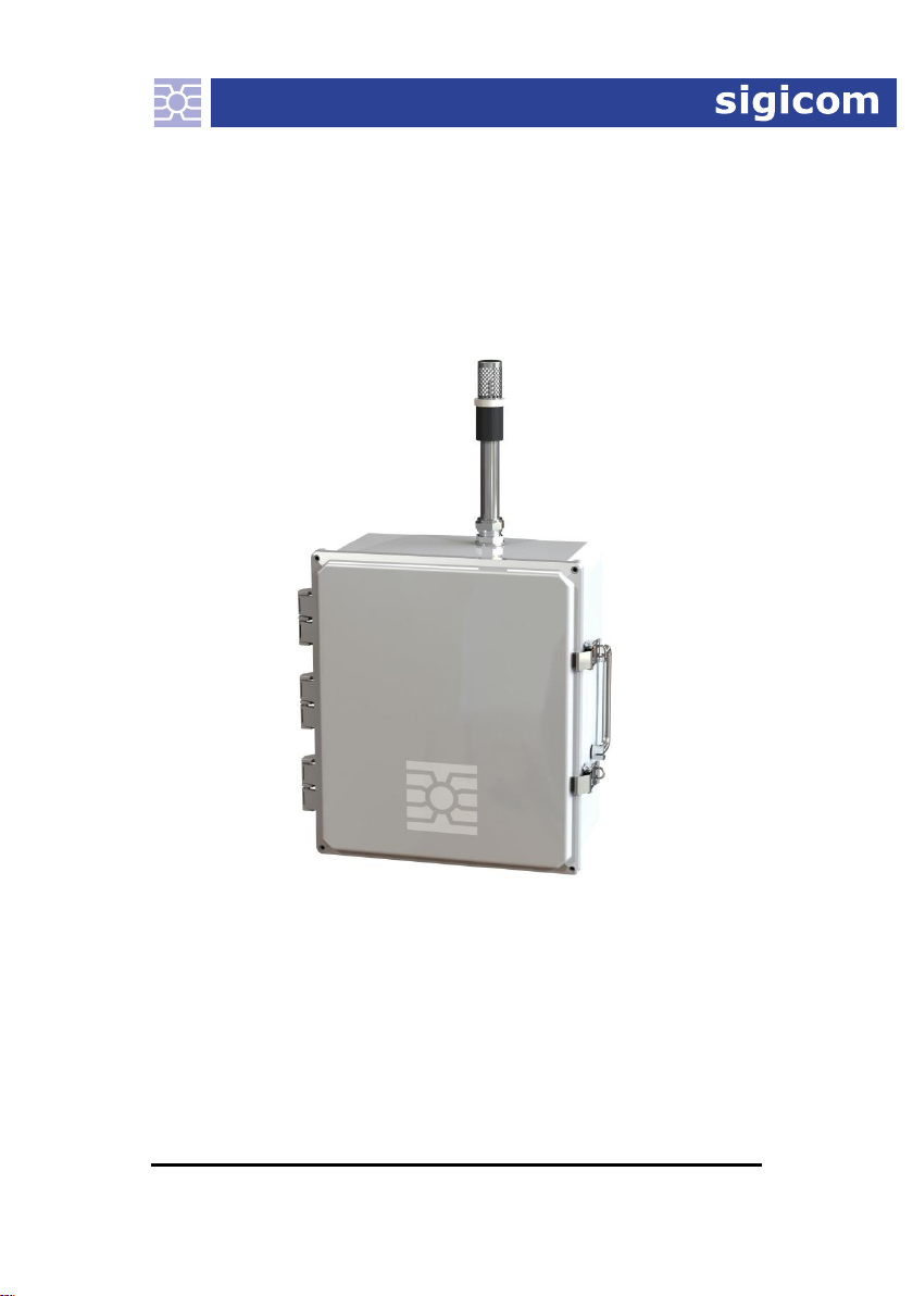
INFRA X20DM2
Dust Monitor
Art no. 080-02550-0
Manual ver. D Valid for firmware version 1.1.0


Copyright ©Sigicom AB 2003-2015
1
Developed and manufactured by:
Sigicom AB
Alfred Nobels Allé 214
SE –146 48 Tullinge, Sweden
IMPORTANT SAFETY INSTRUCTIONS –read this before use.
Read instructions on electrical equipment waste before operating this product.
This equipment falls under the Waste Electrical and Electronic
Equipment Directive (WEEE directive) 2002/96/EC with its last
update 2009, category 9: monitoring and control instruments:
Scrapped equipment should be sent back to the manufacturer of
the equipment (Sigicom) for proper handling according to the
WEEE directive.
Sigicom’s partner for recycling of scrapped equipment is Hans
Andersson Recycling Stockholm AB, with transport certificate
no. 562-1372-2012 (Länsstyrelsen i Stockholms län).

2 Copyright ©Sigicom AB 2003-2015
Contents
1 Introduction.....................................................................................3
1.1 About this manual.............................................................3
1.2 Unpacking and Parts Identification ..................................4
1.3 Safety................................................................................4
1.4 Assembly the external power supply................................5
2General description ....................................................................7
2.1 INFRA Field Monitoring system .............................................7
3Configuration and operation ......................................................8
3.1 Parameters ........................................................................8
3.2 Mounting ........................................................................10
3.3 Start-up instruction .........................................................10
3.4 Error checking ................................................................11
3.5 Failure recovery..............................................................11
4Calibration and Maintenance ...................................................12
4.1 Calibration..............................................................................12
4.2 Minor maintenance.................................................................12
4.3 Repair.....................................................................................15
5Accessories ..............................................................................16
6Contact and support .................................................................17
Appendix A Product Data...............................................................18
A.1 Power consumption...............................................................18
A.2 Range, resolution and accuracy.............................................18
A.3 Mechanical data ....................................................................18
A.4 Air flow.................................................................................19
Appendix B Error handling............................................................20
Appendix C Example of a Dust concentration monitoring ............21
Appendix D Product Conformity Certificate .................................22

Copyright ©Sigicom AB 2003-2015
3
1 Introduction
Welcome to INFRA X20DM2 Dust monitor, which is an integration
of the Osiris Environmental Monitor
1
into Sigicom’s INFRA Field
Monitoring System. For details regarding Osiris, for example its
technology, please read the manual from Turnkey Instruments Ltd.
X20DM2 Dust monitor is intended to be used as a unit in your
INFRA Field Monitoring System. For a comprehensive description
of the INFRA Monitoring System please consult the INFRA Master
manual.
1.1 About this manual
This manual covers the following topics:
Chapter 1 –Introduction. Some introductory information
about unpacking and safety, and also an instruction how to
assembly the external power cable.
Chapter 2 –General description. An overview of X20DM2
and the INFRA Field Monitoring System.
Chapter 3 –Configuration and operation. Description of
X20DM2’s standards and parameter settings, and a start-up
instruction.
Chapter 4 –Calibration and Maintenance information.
Chapter 5 –Accessories. Lists the X20DM2-related
accessories for the INFRA Field Monitoring System.
Chapter 6 –Contact and support. Contact information to
Sigicom AB.
1
from Turnkey Instruments Ltd.

4 Copyright ©Sigicom AB 2003-2015
1.2 Unpacking and Parts Identification
Your X20DM2 has been shipped in protective packaging. Please
verify the package content with the following list:
Cabinet, including Osiris dust monitor
Power supply (battery eliminator, art.no 080-01671-0)
Container with filters for one-year-use.
Calibration certificate (Turnkey Instruments Ltd.)
Maintenance book (Turnkey Instruments Ltd.)
Please report any damage or shortage immediately to Sigicom.
Record the instrument’s serial number. You will be asked to give this
number in any X20DM2 related communication you may have with
Sigicom.
1.3 Safety
Do never open the Osiris dust monitor
2
, or the X20 box.
Do never attach the sensor contact of your X20DM2 to any
other system than cables and units within the INFRA Field
Monitoring System.
Warning! When running the instrument on Standard 1, the
heating element and the inlet tube of the dust monitor gets
hot. The heating element is a white cylinder on the inlet
pipe, connected with two cables, see picture below.
2
For description on filter change, see section 4.

Copyright ©Sigicom AB 2003-2015
5
1.4 Assembly the external power supply
1. Take out the bushing, see the picture above.
2. Remove one of the white plastic cylinders, and cut a slit in
the bushing on its side towards the hole (from the cylinder).
3. Put the low voltage side of the external power cable in the
slit such that its seal fills out the hole.

6 Copyright ©Sigicom AB 2003-2015
4. Put back the bushing, see the picture above.
5. Connect the plugs inside the cabinet, see the picture below.

Copyright ©Sigicom AB 2003-2015
7
2General description
X20DM2 simultaneously monitors the concentrations of:
PM10
PM2.5
PM1
TSP, Total Suspended Particle
Each channel measures its average value over the selected interval
time.
The channels are all synchronized and their values are sent to the
connected INFRA Datalogger, which stores them on its local
memory card, and uploads them to the dedicated data server. The last
interval value of channel 1 (PM10) can also be viewed in the
Datalogger display.
2.1 INFRA Field Monitoring system
The INFRA contact placed on the bottom of the cabinet shall be
connected to the INFRA Field Monitoring System by any of the
available INFRA Sensor Cables. This will handle the communication
with the Datalogger
3
. Normally, the cabinet needs also to be
connected to external power supply.
Within INFRA Field Monitoring System it is possible to measure a
number of other quantities simultaneously with the dust
measurements, for example:
vibration (geophone) in one direction
vibration (geophone) in three directions
sound level
air blast
weather (wind, rain, humidity, temperature)
etc.
3
The main unit in the INFRA Field Monitoring System

8 Copyright ©Sigicom AB 2003-2015
3Configuration and operation
3.1 Parameters
The parameters described below are normally set using INFRA Net
Manager (Remote control), but can also be set using the display and
push-buttons of the Datalogger.
3.1.1 Standards
X20DM2 has two selectable standards, S01 and S02.
S01: The inlet air is heated. This standard is intended to be selected
when air humidity is above 50 %RH.
Note! This standard needs external power, because the battery of
Osiris is too weak to power the heating elements. If external power is
lost in this standard, the interval data will be tagged with
“Overload”.
S02: The inlet air is without heating. The instrument can be run
without external power for at least eight hours when Osiris internal
battery is fully charged.
Common for the two standards is that they deliver the four measured
channels:
Channel 1. PM10 Concentration.
Channel 2. PM2.5 Concentration.
Channel 3. PM1 Concentration.
Channel 4. TSP Concentration (Total Suspended Particle).
Each of these channels is the average value measured over the
selected Interval time. The unit of each channel is µg/m3.

Copyright ©Sigicom AB 2003-2015
9
3.1.2 Interval time
The interval time is how often the measured value of each channel is
registered
4
. The interval time can be selected to one of:
1, 2, 4, 5, 6, 10, 15, 20, 30 and 60 minutes
The default value is 15 minutes.
3.1.3 Upper threshold level
If the concentration of PM10 (channel 1) becomes larger than this
level, the Datalogger sends an updated interval file to the Data
server. Simultaneously, an (SMS or Server message) alarm is
possibly sent, dependent on your settings.
The Upper threshold level can be set to any value in the interval
5 –5000 µg/m3. There is also a parameter telling whether threshold
shall be used or not.
Note! Upper threshold level is only defined for PM10 (Ch. 1). This
means that it is not possible to trigger an SMS on any of the other
channels.
3.1.4 Customer string
The customer string consists of four characters, and can be selected
by the user. The default string is “DUST“.
4
stored in interval files.

10 Copyright ©Sigicom AB 2003-2015
3.2 Mounting
Please use the included hardware for pole mounting. Try to site the
monitors as near the point of public exposure as possible. For model
validation, it is important to cover a range of urban background and
roadside sites, if possible.
3.3 Start-up instruction
1. Connect your X20DM2 with one INFRA Datalogger (Master,
Mini or Micro) by using any of the available INFRA Sensor
Cables.
2. Connect X20DM2 to the external power. Osiris will then start
automatically.
Note! If you want to run without external power, you need to
manually start the Osiris by pressing its “ON - Reset” key. The
instrument can be run without external power for at least eight
hours when Osiris is fully charged.
3. Start the Datalogger and wait for the initialization process to be
finished.
4. Make necessary adjustments of the parameters:
• Standard (S01 or S02)
• Interval time
• Upper threshold level (on/off, and value if on is selected)
• Customer string
via Remote Control in the PC-application INFRA Net Manager,
or directly by using the Master display and buttons.
Note! Each standard has its own parameters (Interval time,
Upper threshold level, and Customer string).
5. Activate REG ON, and the measurement will be initiated.

Copyright ©Sigicom AB 2003-2015
11
3.4 Error checking
If there is a major malfunction, for example the Osiris dust monitor
stops because of no external power and the internal battery runs
empty, the Datalogger will display “Node lost” after a delay equal to
the selected interval time, see Appendix B Error handling for
details. To recover, after the error is fixed, try to make a “Forced
reboot” of the Datalogger (can be made from INFRA Net Manager).
Standard 1 needs external power, because the battery of Osiris is too
weak to power the heating elements. If external power is lost when
using this standard, the interval data will be tagged with “Overload”.
Also standard 2 need external power if we want to run for more than
one day.
3.5 Failure recovery
During start-up it might happen that the INFRA Datalogger says
"Node lost", but the Osiris is on (active). In this case it is
recommended to reboot the Osiris:
1. Stop registration (Reg off) and shut down the INFRA
Datalogger.
2. Remove external power from your X20DM2.
3. Shutdown the Osiris by simultaneously press the two buttons
"(START) STOP" and "" (left arrow)
4. Check that the display of Osiris doesn't show anything.
Otherwise redo the previous task.
5. Wait at least 5 seconds
6. Put back external power to your X20DM2.
7. Check that the Osiris display wakes up. Otherwise redo the
previous task.
8. Start registration (Reg On).

12 Copyright ©Sigicom AB 2003-2015
4Calibration and Maintenance
4.1 Calibration
Recommended calibration interval is 12 months. Please send the
X20DM2 cabinet to Sigicom AB for calibration and adjustment. See
contact information in section 6.
4.2 Minor maintenance
4.2.1 Flow and filter check
The Osiris dust monitor requires a flow and filter check every 3
months. If this indicates that the weight of the deposited particles on
the filter has been above a certain limit, a filter change is needed.
Follow the list below to perform the flow and filter check:
1. Stop sampling by doing “Reg off” at your INFRA
Datalogger.
2. Shutdown the Datalogger (you must wait until all files have
been uploaded).
3. Remove external power.
4. Remove the two connectors from the Osiris.
5. Gently remove the inlet tube from the Osiris.
Warning! Inlet may be hot!
6. Loosen the two nuts to the left of the Osiris.
7. Lift the Osiris out of the cabinet and put it on a table.
8. If the Osiris display is blank, start the Osiris (Press ON).
9. Press ENTER.
10. Press several times until display reads “Filter and
ManFLOW” or “Filter and AutFLOW”.
11. Press ENTER.
12. Record “Used mins” in your log (e.g. Maintenance book:
Filter mins).
13. Press RESET.
14. Record filter weight in your log.
15. Press RESET.
16. Record pump hours in your log.

Copyright ©Sigicom AB 2003-2015
13
17. If filter weight is 3.0 mg or more, change filter. See section
4.2.2 for a detailed description.
18. If you changed the filter:
i) press RESET.
ii) press ENTER.
iii) press START three times (password).
iv) press ENTER to confirm filter change.
If not:
i) press RESET twice.
19. Connect your flow meter to the Osiris inlet located above
the display.
20. Hold the flow meter vertical. Adjust the flow by pressing
or until flow meter shows 600 ml/min.
21. When flow rate is correct, press ENTER, and record the
change in your log.
22. Remove flow meter and press RESET.

14 Copyright ©Sigicom AB 2003-2015
4.2.2 Filter change
1. Unscrew the three screws from the filter cap using the
Allen-key from your Tool kit, see picture below. The cap
contains the filtered secured by an O-ring.
2. Replace filter. Remember to reinsert the O-ring. Check the
O-ring is in good condition.
3. Check the smaller O-ring for the off-center exhaust tube on
the base.
4. Replace the filter holder. Make sure the small O-ring is
aligned with the exhaust tube in the base before refitting the
filter cap. To do this, the small O-ring should be to the rear
when the filter cap is refitted.
Note! Do not overtighten.

Copyright ©Sigicom AB 2003-2015
15
4.3 Repair
If sent to repair (to Sigicom), please carefully write down the
description of the problem. Here it is important to keep the cabinet as
it is, and send it in as one unit. It is also recommended to contact
Sigicom before sending the unit.

16 Copyright ©Sigicom AB 2003-2015
5Accessories
Accessories suitable for X20DM2 when connecting it to the INFRA
Field Monitoring System:
Filters for Dust Monitor 2, art.no 080-02550-1
Battery eliminator, art.no 080-01671-0
Flow meter for Dust Monitor 2, art.no 080-02550-2
Pole/Wall Mount Kit, art.no 080-01862-1 and 080-01864-4
Lockable bracket, art.no 080-01853-0
Tool kit for Dust monitor 2, art.no 080-01891-2
Transport case for Dust monitor 2, art.no 080-01887-0
Sensor drop cable 0.3m (1.0ft), art.no 080-01100-0
Sensor drop cable 1.0m (3.3ft), art.no 080-01101-0
Sensor drop cable 2.0m (6.6ft), art.no 080-01102-0
Sensor drop cable 5.0m (16ft), art.no 080-01105-0
Sensor cable 15m (49 ft), art.no 080-01115-0
Sensor cable 40m (131ft), art.no 080-01140-0
Sensor cables in other lengths on special order,
please contact Sigicom AB.
Self-vulcanizing tape, art.no 080-01892-0
Cable winder (max. 50m), art.no 080-01200-0
Window feed through cable, art.no 080-01472-0
T-port, art.no. 080-01230-1
Termination plug, art.no 080-01236-0
Feed through connector, art.no 080-01239-0


18 Copyright ©Sigicom AB 2003-2015
Appendix A Product Data
A.1 Power consumption
The measuring function of X20DM2 consumes approximately 2.3W.
The heating function, which is active in Standard 1, consumes
additionally 12W.
A.2 Range, resolution and accuracy
The data in this section are given by Turnkey Instruments
(www.turnkey-instruments.com).
Measurement range
PM10 and TSP (Channel 1 and 4): 0.1 to 6000 µg/m3
PM2.5 and PM1 (Channel 2 and 3): 0.01 to 600 µg/m3
Detection limit
0.01 µg/m3
Operating temperature
-5 °C to 40 °C (23 to 104 °F)
Technical data may be subject to change without notice.
A.3 Mechanical data
Size61 x 32 x 19 cm (24 x 13 x 7.5 in)
Housing protection class
IP 67
Total weight (incl. hardware for mounting)
10 kg (22 lbs)
Table of contents
Other Sigicom Monitor manuals


