SIGNAL INSTRUMENT Signal User manual

The SIGNAL INSTRUMENT Co. Ltd.
12 Doman Road, Camberley
Surrey, GU15 3DF
England
Tel: +44 (0) 1276 682841
Fax: +44 (0) 1276 691302
Part Number 250/335050
250SM COOLER DRYER
OPERATING MANUAL

250SM OPERATING MANUAL
Page 2 of 26 250/335050 Issue 1.01
DOCUMENT HISTORY
ISSUE AMENDMENT DATE
1.00 First Issue December 9,1996
1.01 Addition of Warranty Statement January 6, 1999

250SM OPERATING MANUAL
250/335050 Issue 1.01 Page 3 of 26
© The Signal Instrument Co. Ltd.
All rights reserved. No part of this manual may be reproduced, stored in a retrieval system or transmitted
in any form or by any means - electronic, mechanical, photocopying, recording or otherwise - without the
prior written permission of The Signal Instrument Co. Ltd.
While we believe that the information and guidance given in this manual is correct, all parties must rely
upon their own skill and judgement when making use of it. The Signal Instrument Co. Ltd. will not assume
any liability to anyone for any loss or damage caused by any error or omission in the manual, whether such
error or omission is the result of negligence or any other cause. Any and all such liability is disclaimed.

250SM OPERATING MANUAL
Page 4 of 26 250/335050 Issue 1.01
CONTENTS
1. INTRODUCTION................................................................................................................7
1.1 Cooler............................................................................................................................................................7
1.2 Applications..................................................................................................................................................7
1.3 Getting Started ..............................................................................................................................................7
1.4 Special Requirements....................................................................................................................................7
2. SPECIFICATION................................................................................................................8
2.1 Sample Heat Removal...................................................................................................................................8
2.2 Sample Input.................................................................................................................................................8
2.3 Sample Outlet................................................................................................................................................8
2.4 Response time...............................................................................................................................................8
2.5 Peristaltic Pump ............................................................................................................................................8
2.6 Environment..................................................................................................................................................8
2.7 Power ............................................................................................................................................................9
2.8 Analogue Output...........................................................................................................................................9
2.9 Alarm Limits.................................................................................................................................................9
2.10 Alarm Relay................................................................................................................................................9
2.11 Physical Dimensions...................................................................................................................................9
2.12 Sample Path.................................................................................................................................................9
2.13 Safety ..........................................................................................................................................................9
3. INSTALLATION...............................................................................................................11
3.1 Introduction.................................................................................................................................................11
3.2 Typical Application Configurations............................................................................................................11
3.3 Basics..........................................................................................................................................................12
3.4 Location ......................................................................................................................................................13
3.5 Mains Power Connections ..........................................................................................................................13
3.6 Gas Connections .........................................................................................................................................15
3.7 Water Drain.................................................................................................................................................15
3.8 Alarm Relay................................................................................................................................................15
3.9 Alarm Connections .....................................................................................................................................15
4. BASIC OPERATION........................................................................................................17
4.1 Introduction.................................................................................................................................................17
4.2 Installation...................................................................................................................................................17
4.3 Start Up.......................................................................................................................................................17
4.4 Shut Down ..................................................................................................................................................17
5. OPERATION .....................................................................................................................18
5.1 Introduction.................................................................................................................................................18
5.2 Description..................................................................................................................................................18
5.3 Alarm Conditions........................................................................................................................................19
5.4 Using The Alarm Relay ..............................................................................................................................19
5.5 Controlling Signal Analysers......................................................................................................................20
5.6 Remote Temperature Monitoring................................................................................................................20
6. TROUBLE SHOOTING...................................................................................................21
6.1 Intermittent Water Alarm............................................................................................................................21
6.2 Output Dew Point Deviations .....................................................................................................................21
6.3 Sample Dew Point.......................................................................................................................................21
7. TECHNICAL DESCRIPTION.........................................................................................22
7.1 Description..................................................................................................................................................22
7.2 Peltier Cooling Elements.............................................................................................................................22

250SM OPERATING MANUAL
250/335050 Issue 1.01 Page 5 of 26
8. ROUTINE MAINTENANCE...........................................................................................23
8.1 Catch Pot Water Removal ...........................................................................................................................23
8.2 Peristaltic Pump Tube Replacement............................................................................................................24
8.3 Fuse Replacement........................................................................................................................................24
8.4 Spares Kit....................................................................................................................................................24
9. ROUTINE SERVICING...................................................................................................25
9.1 Policy...........................................................................................................................................................25
9.2 Servicing......................................................................................................................................................25
9.3 Spares Kit....................................................................................................................................................25
10. WARRANTY....................................................................................................................26
Tables
Table 1 Fuse and VA Rating..................................................................................................................................9
Figures
Figure 1 Channel Performance...............................................................................................................................8
Figure 2 Typical CEM Configuration..................................................................................................................11
Figure 3 Typical Automotive Configuration........................................................................................................11
Figure 4 Sample Heat Content.............................................................................................................................12
Figure 5 Channel Performance.............................................................................................................................13
Figure 6 Connection Panel Layout.......................................................................................................................14
Figure 7 Alarm Connector....................................................................................................................................15
Figure 8 Front Panel Controls and Indicators ......................................................................................................18
Figure 9 Upstream Pump Control ........................................................................................................................19
Figure 10 Downstream Solenoid Control.............................................................................................................19
Figure 11 Controlling a Signal Analyser..............................................................................................................19
Figure 12 Sample Dew Point Estimation .............................................................................................................21
Figure 13 Peristaltic Tube Connections ...............................................................................................................23
Figure 14 Flow Diagram......................................................................................................................................24

250SM OPERATING MANUAL
Page 6 of 26 250/335050 Issue 1.01

250SM OPERATING MANUAL INTRODUCTION
250/335050 Issue 1.01 Page 7 of 26
1. INTRODUCTION
1.1 Cooler
1.1.1 The 250SM cooler is based on the solid state Peltier element and include a continuous
peristaltic drain pump. It is intended for OEM applications in the emissions monitoring
market.
1.1.2 A conditioned sample with a dew point of 5 °C can be obtained from a hot sample gas of
up to 210 °C and having a dew point of up to 70 °C.
1.1.3 Water and dual temperature alarms, and a temperature monitor output are a standard
feature for each channel.
1.2 Applications
1.2.1 These cooler dryer is used to provide a conditioned sample to those analysers not having
a heated sample system, or where they are susceptible to cross interference from water
vapour.
1.3 Getting Started
1.3.1 Installation.
1.3.1.1 Unless you are familiar with the installation of gas coolers, we recommend that you
read section 3 from start to finish.
1.3.2 Operation
1.3.2.1 Read all of section 4 for the minimum steps necessary to get your cooler working.
Then read all of section 5 to learn more about the cooler.
1.3.3 Maintenance
1.3.3.1 Read the section 8 to keep your cooler in first class condition.
1.4 Special Requirements
1.4.1 Location
1.4.1.1 The cooler transfers heat from the sample to the local ambient air. Cold air is taken
from local ambient at the mounting face; heat is transferred to it and it is vented out
from the opposite face. The colder the local ambient air, the more efficient the cooler
performance. The hot air must not be allowed to recirculate back to the cooler. Read
the installation section carefully.
1.4.2 Sample flow
1.4.2.1 The sample must be passed through the cooler.. This is best achieved with an upstream
heated pump and bypass control system.
1.4.2.2 Best results and reliable performance are achieved when the sample is pulse free.
1.4.3 Sample filter
1.4.3.1 A particulate filter should be fitted before the cooler.

SPECIFICATION 250SM OPERATING MANUAL
Page 8 of 26 250/335050 Issue 1.01
2. SPECIFICATION
2.1 Sample Heat Removal
2.1.1 Maximum 18 W at 25 °C ambient.
2.1.2 Figure 1 shows the maximum cooling capability over the ambient temperature range.
2.2 Sample Input
2.2.1 Maximum inlet temperature 210 °C.
2.2.2 Maximum dew point 70 °C.
2.2.3 ¼" tube fitting.
2.2.4 Inlet Pressure -5 psig to +15 psig.
2.3 Sample Outlet
2.3.1 Output Dew Point +5 °C ±0.5 °C non adjustable.
2.3.2 ¼" tube fitting per channel.
2.3.3 Maximum 3 l/min per channel.
2.3.4 Pressure difference input to output < 0.2 psig (6" WG) at 2 l/min, 190 °C, and 50 % dew
point sample.
2.4 Response time
2.4.1 Ready for use within 30 minutes of switch on with no sample flowing.
2.5 Peristaltic Pump
2.5.1 Maximum Pressure at outlet into which it will pump is 5 psig.
2.6 Environment
2.6.1 Ambient Temperature +5 °C to 40 °C.
2.6.2 Relative Humidity to 95 % non-condensing
2.6.3 Keep out of direct sunlight and other forms of radiant heat.
5 10152025303540
Ambient Temperature °C
0
2
4
6
8
10
12
14
16
18
20
Watts
Channel Capability
Figure 1 Channel Performance

250SM OPERATING MANUAL SPECIFICATION
250/335050 Issue 1.01 Page 9 of 26
2.7 Power
2.7.1 Dual voltage 115 Vac ±15% or 230 Vac ±15% selectable from the rear panel.
2.7.2 Mains fuse sizes are all 5 x 20 mm. HBC
2.8 Analogue Output
2.8.1 Non-isolated voltage output proportional to channel temperature in the range 0 - 50 °C.
100 mV represents 1 °C. Accuracy ±0.7 °C over the range.
2.8.2 Continuous short circuit allowed. Recovery < 15 min.
2.9 Alarm Limits
2.9.1 High
2.9.1.1 Channel temperature > 5 °C above the control temperature.
2.9.2 Low
2.9.2.1 Channel temperature < 1 °C below the control temperature.
2.9.3 Water
2.9.3.1 Alarm when there is more than 20 mL of static water in the catch pot.
2.10 Alarm Relay
2.10.1 Volt free dual change-over relay contacts with the de-energised sate representing the
alarm condition.
2.10.2 Contact ratings 1 A at 50 Vdc.
2.10.3 Isolation > 10 MΩat 50 Vdc.
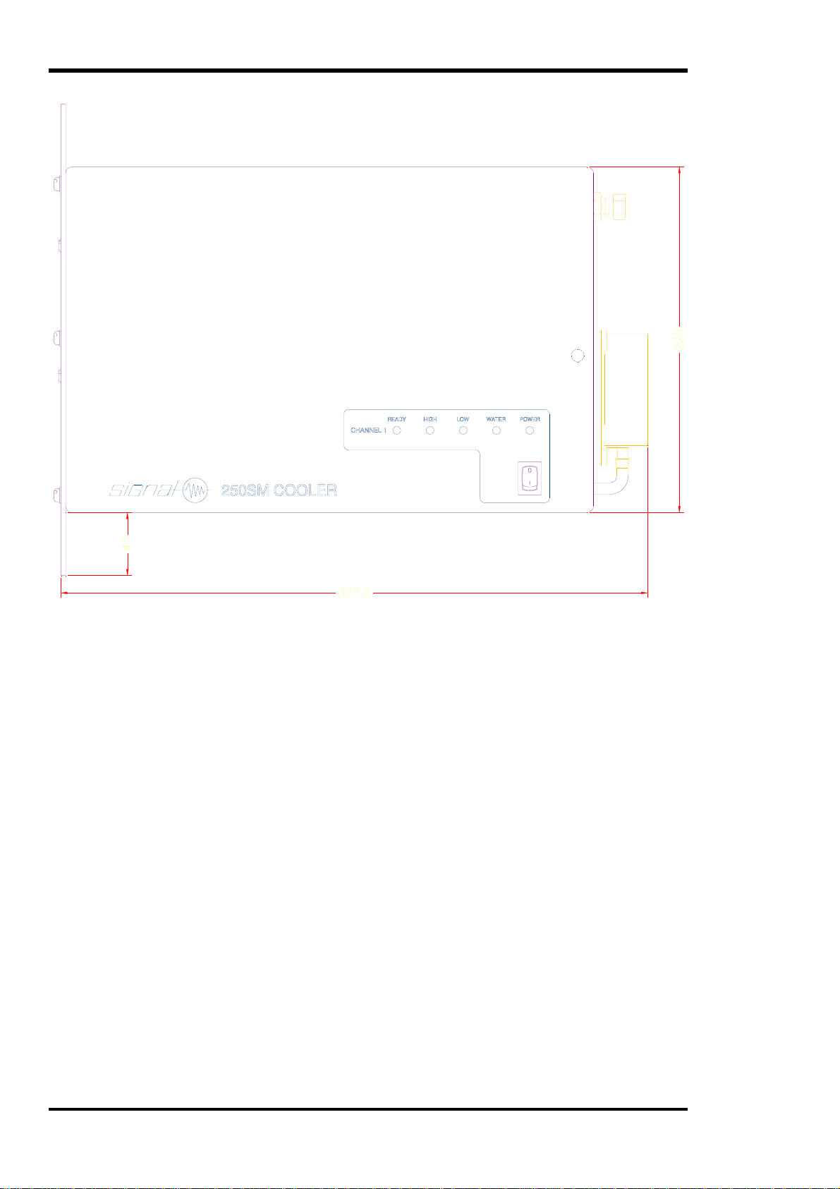
2.11 Physical Dimensions
2.11.1 Width 218 mm.
2.11.2 Body Height 220 mm.
2.11.3 Height including mounting ears 300 mm.
2.11.4 Depth from mounting face 374 mm.
2.11.5 Only the ears are free from protrusions on the mounting face. Refer to section 3
2.11.6 Weight 15 kg.
2.12 Sample Path
2.12.1 Materials in contact with the sample are :-
2.12.1.1 316 Stainless Steel
2.12.1.2 PTFE
2.12.1.3 PVDF
2.13 Safety
2.13.1 The cooler has been constructed in accordance with prescribed safety standards. All
hazardous circuits are shielded.
Supply 115 Vac 230 Vac
VA 180 180
Fuse 4 AT 2 AT
Table 1 Fuse and VA Rating
SPECIFICATION 250SM OPERATING MANUAL
Page 10 of 26 250/335050 Issue 1.01
250SM OPERATING MANUAL INSTALLATION
250/335050 Issue 1.01 Page 11 of 26
3. INSTALLATION
3.1 Introduction
3.1.1 Installation requires the use of a tool set compatible with electrical and pneumatic skills.
A suitable set of tools for a minimum installation consists of and electricians flat bladed
screwdriver for the mains connections, a sharp knife for cutting PTFE tubing, a 9/16"
(14.3 mm) A/F spanner for ¼" fittings. Full installation of chart recorder, and other
features may require the use of a soldering iron plus solder, wire cutters, wire strippers,
small pliers, and a working knowledge of the equipment to be connected. Plumbing in
stainless steel will require the use of pipe cutters and benders. We, or our local agents,
can offer an installation service if you do not have the necessary skills.
3.2 Typical Application Configurations
CAUTION
THE COOLER MUST NOT BE USED WITHOUT A
SAFETY EARTH CONNECTION.
After connection to a source of hot sample, the inlet port may become hot.
TAKE PRECAUTIONS AGAINST BURNS.
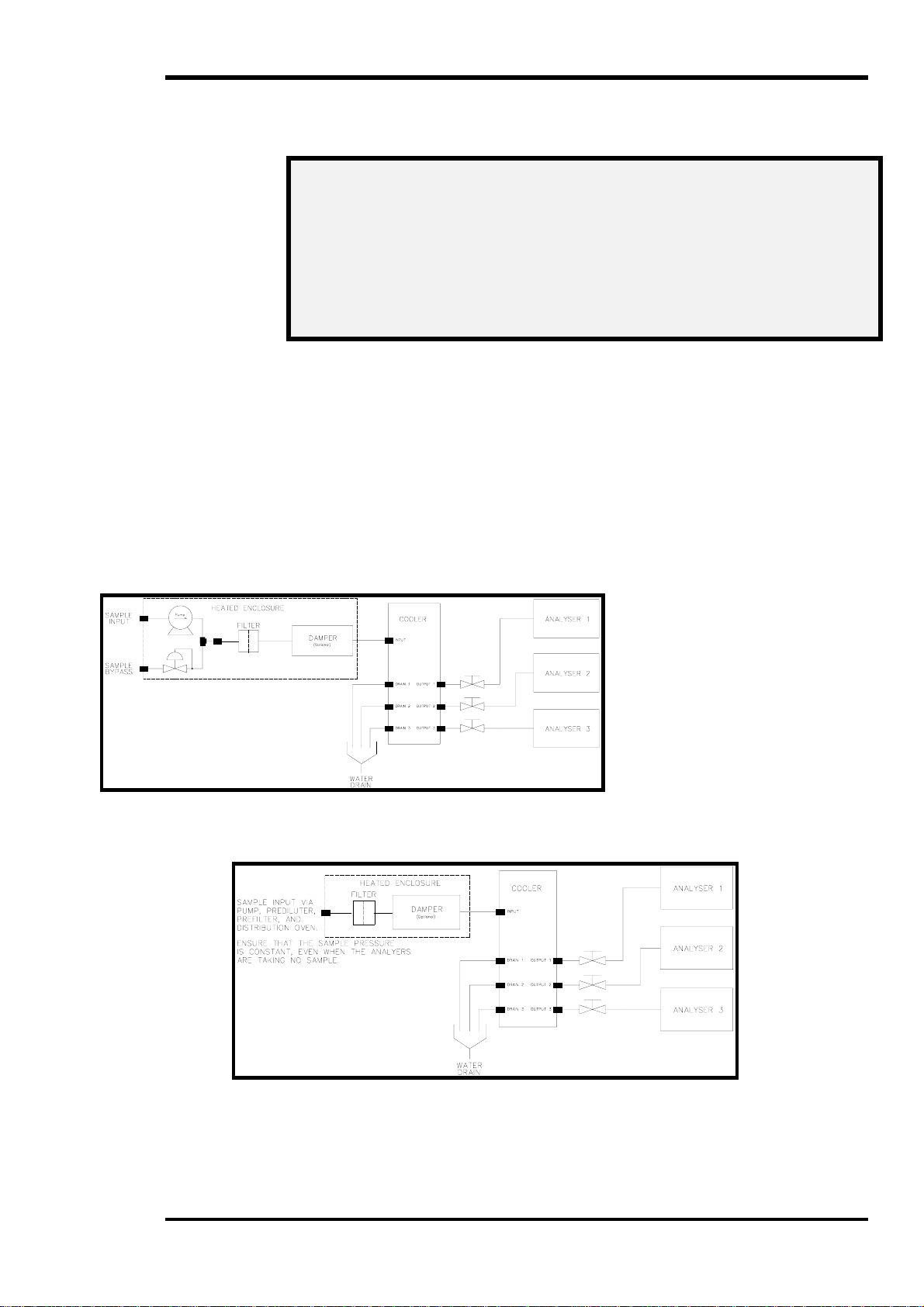
Figure 2 Typical CEM Configuration
Figure 3 Typical Automotive Configuration

INSTALLATION 250SM OPERATING MANUAL
Page 12 of 26 250/335050 Issue 1.01
3.3 Basics
3.3.1 Cooler performance is a compromise between installation environment and sample
condition.
3.3.2 The ambient temperature surrounding the cooler sets an upper limit to the amount of heat
that can be extracted from the sample.
3.3.3 The amount of heat to be removed is a function of the sample dew point and temperature,
and the rate of heat removal is directly proportional to flow rate.
3.3.4 Estimate the heat extraction rate required to cool 1 L/min sample using Figure 4 and
calculate total rate by multiplying by the required flow rate..
3.3.5 From the performance graph in Figure 5 determine the maximum ambient temperature
allowed for this performance.
3.3.6 In severe cases it may be necessary to provide air conditioning for the cooler to reduce
the ambient temperature or to add another cooler to spread the load.
0 1020304050607080
Raw Sample Dew Point °C
0
2
4
6
8
10
12
14
16
18
20
22
Watts
100 °C
145 °C
191°C
210°C
Sample Heat Content
For each L/min Sample Flow and for various Sample Temperatures
Figure 4 Sample Heat Content

250SM OPERATING MANUAL INSTALLATION
250/335050 Issue 1.01 Page 13 of 26
3.4 Location
3.4.1 Observe the environmental limitations listed in the specification section.
3.4.2 The cooler is designed to be mounted at the rear of a rack system to keep the rack panel
space clear. It must be mounted so that the inlet (on the mounting face) has access to
cold air. It will vent heated air into the rack. This air must be prevented from circulating
back to the inlet.
3.5 Mains Power Connections
3.5.1 Mains Voltage
3.5.1.1 Check your local mains voltage. It must fall inside the ±15% limits of the nominal
115 Vac or 230 Vac settings of the mains selector switch.
3.5.1.2 Set the switch to the corresponding setting and check that the fuse ratings and types
fitted comply with those given is section 2.7. A spare set of fuses is supplied in the
accessory kit.
3.5.2 Wiring
3.5.2.1 The mains lead supplied with the analyser is colour coded and must be connected
according to the following instructions to make the cooler safe for use.
3.5.2.1.1 Connect the BROWN wire to the LIVE (L) pin of the mains plug.
3.5.2.1.2 Connect the BLUE wire to the NEUTRAL (N) pin of the mains plug.
3.5.2.1.3 Connect the GREEN/YELLOW wire to the EARTH (E) pin of the mains plug.
3.5.2.2 Earthing
5 10152025303540
Ambient Temperature °C
0
2
4
6
8
10
12
14
16
18
20
Watts
Channel Capability
Figure 5 Channel Performance
INSTALLATION 250SM OPERATING MANUAL
Page 14 of 26 250/335050 Issue 1.01
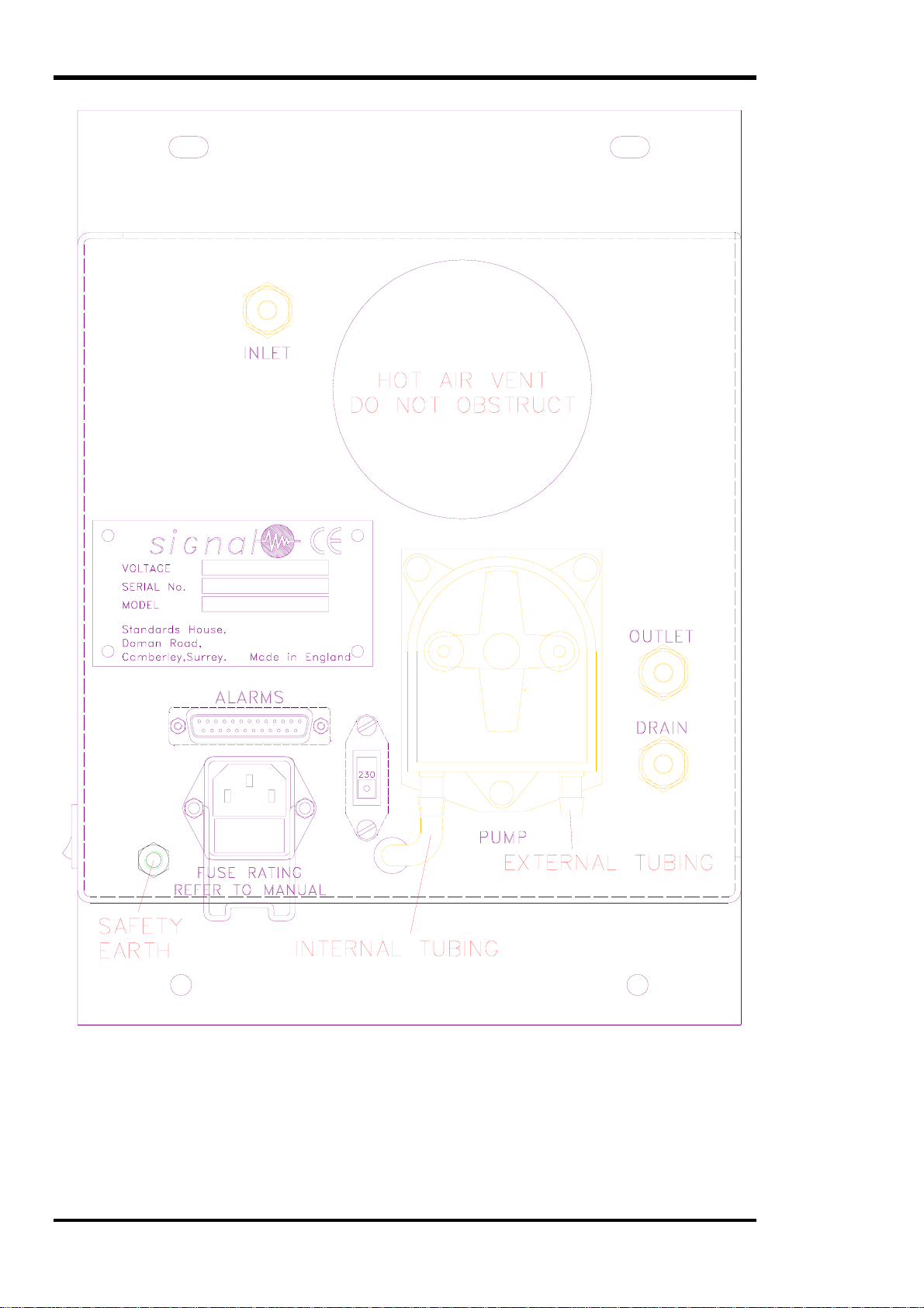
3.5.2.2.1 The cooler must be used with a safety earth. If your mains supply has no earth
terminal, a separate earth must be connected to the M6 stud on the rear panel. This
stud can be used to provide a common ground or screen when data logging. Consult
a qualified electrician if you have no earth at all.
Figure 6 Connection Panel Layout

250SM OPERATING MANUAL INSTALLATION
250/335050 Issue 1.01 Page 15 of 26
3.5.2.3 No Local Earth
3.5.2.3.1 If the local mains supply does not provide an earth connection, you must supply an
independent one. Consult a qualified electrician.
3.5.2.3.2 A mains distribution panel should be installed to provide earthed power outlets for
the cooler and all associated equipments. You may wish to include extra facilities
for data recording or computer facilities at the same time.
3.6 Gas Connections
3.6.1 Input
3.6.1.1 The input must be filtered to prevent accumulation of particulate within the cooling
channels.
3.6.1.2 The input should also be pressurised, within the limits in the specification, to create
flow through each channel. The flow should be pulse free to prevent water carry-over.
The possibility of water carry-over is increased if down stream pumping is used.
3.6.1.3 An input bypass must be provided so that the inlet pressure is controlled if all analysers
are switched off or are calibrating and not using sample gas. Automotive applications
normally have an up-stream heated sample pump with a bypass control and prefilter as
part of the sample system. CEM applications will need at least a heated pump and
bypass regulator. You can purchase standard parts from us if you wish. Contact our
sales department.
3.6.1.4 Connect the sample source to the ¼" fitting labelled INPUT.
3.7 Water Drain
3.7.1 Condensate from the sample is removed by a peristaltic pump on the rear panel. The
condensate may be acidic and should be treated as hazardous waste in accordance with
your local regulations. Typical contents could include Nitric Acid, Nitrous Acid,
Sulphurous Acid, Sulphuric Acid, Carbonic Acid. Ensure that all pipe work and fittings
used to route the water to a safe dump point are resistant to these acids and any others
that could be produced when your sample gas comes into contact with water.
3.7.2 The outlet of the peristaltic pump should not be restricted.
3.7.3 Connect silicon or other suitable tubing to the outlet (nozzle to the right of the pump and
attached to the pump tube) of each peristaltic pump and route to the drain point.
3.7.4 It is important that the drain point is insulated against ambient temperature to protect
against freezing. This would block the pipe and prevent water removal.
3.8 Alarm Relay
3.8.1 The cooler has an independent alarm relay.
The relay has two independent change-over
contact sets available on the rear panel. The
contacts are only rated for low power (refer
to section 2.10) and must be used with an
auxiliary relay to control mains operated or
high power devices.
3.9 Alarm Connections
3.9.1 The output connector and pin out is the same
as that used on the 200SM series of rack
mounted coolers. Only the connections for
channel 1 are used in this cooler. It is
important to preserve the EMC compliance
by using the connector supplied in the
accessory kit with a suitable braided cable.
The cable braid must have a continuous
connection between the cooler and the
Figure 7 Alarm Connector

INSTALLATION 250SM OPERATING MANUAL
Page 16 of 26 250/335050 Issue 1.01
measurement or control equipment. A screened junction box will be necessary if the
cable is to be split to serve multiple outlets.
3.9.2 Figure 7 shows the connector pin identification.

200SM SERIES OPERATING MANUAL BASIC OPERATION
250/335050 Issue 1.01 Page 17 of 26
4. BASIC OPERATION
4.1 Introduction
4.1.1 The following instructions guide you through the steps necessary to achieve sample
cooling.
4.1.2 The cooler has no controls other than the mains on-off switch making it a very simple
device to use.
4.1.3 It is very important that the installation section is read and understood before using the
cooler. The location, environment, and sample conditions all affect the performance and
must be taken into account if a consistent and reliable performance is to be obtained.
4.2 Installation
4.2.1 Install the cooler in accordance with section 3 ensuring that the environmental conditions
are met and that the mains selector switch has been set to suit your local mains supply.
4.3 Start Up
4.3.1 Ensure that there is no sample flow to the analysers. One way is to set all analysers to
measure a ‘ZERO’ gas.
4.3.2 Operate the front panel mains switch and observe the power indicator glowing for each
fitted channel. Wait for the READY indicator on each fitted channel to glow.
4.3.3 The cooler is now ready for use. Select ‘SAMPLE’ on each analyser and cool, de-
humidified sample will be supplied.
4.4 Shut Down
4.4.1 Turn off the sample flow to each analyser. Turn the mains power switch off.

OPERATION 250SM OPERATING MANUAL
Page 18 of 26 250/335050 Issue 1.01
5. OPERATION
5.1 Introduction
5.1.1 This section gives a detailed explanation on the use and operation of the cooler.
5.2 Description
5.2.1 The cooler is contained in a 5U case suitable for bench or rack mounting. All pneumatic
and electrical connections are on one panel. Another panel contains channel indicators
and the mains power switch.
5.2.2 Indicators
5.2.2.1 There is a row of indicators on the front panel showing the cooler status. When the
cooler is switched on, the POWER indicator will glow. Indicators coloured RED warn
that the cooler is not available for use.
5.2.2.2 READY glowing means that the cooler is ready to use.
5.2.2.3 HIGH glowing means the temperature is too high and that the cooler is not ready for
use.
5.2.2.4 LOW glowing means the cooler temperature is abnormally low and indicates a
possible problem. An abnormally low temperature could result in freezing any residual
water in the chamber and causing a blockage. Turn off the sample flow through the
cooler.
o
nt Panel Controls and Indicators

250SM OPERATING MANUAL OPERATION
250/335050 Issue 1.01 Page 19 of 26
5.2.2.5 WATER glowing means that water from the chamber has been ejected into a safety
‘catch pot’ due to abnormal sample pressure surges. Immediately turn off the sample
flow to prevent water carry-over into the analyser. Refer to section 8 for instructions
on clearing the catch pot.
5.3 Alarm Conditions
5.3.1 The appearance of any RED indicator will activate an internal relay. The relay has two
independent change-over contact sets available on the rear panel. The contacts are only
rated for low power and must be used with an auxiliary relay to control mains operated
devices.
5.4 Using The Alarm Relay
5.4.1 The relay contacts can be use to sound a warning alarm and to automatically switch the
sample pump off, or to set Signal Series III analysers to their standby states. Take care
not to exceed the relay contact ratings. An auxiliary relay will be required if you are
driving mains loads or other high voltage, high current devices.
5.4.2 Upstream Pump Control
5.4.2.1 The alarm relay can be used to control an upstream pump so that it will stop if an alarm
condition exists. A latching
relay with a bush-button
start is required. If
sufficient damping can be
provided so that pressure
pulses do not occur when
the pump starts or stops, the
latching relay may not be
necessary.
5.4.2.2 Connect all normally open
contacts from each channel
in series. When an alarm condition exist, the pump will be automatically turned off.
5.4.3 Analyser Valve Control
5.4.3.1 The alarm relay for a particular
channel may be used to control
a downstream solenoid valve
so that there is no flow to an
analyser when an alarm
condition exists. There should
be sufficient damping in the
system so that operating the
solenoid valve does not cause
significant pressure pulses.
5.4.3.2 Connect the normally open
contacts in series with the
control valve. The valve
will close whenever an
alarm condition exists.
24 Vdc
Cooler Channel Relay
Pump Control Relay
Start
Button
Figure 9 Upstream Pump Control
24 Vdc Solenoid
Valve
Cooler Channel Relay
Figure 10 Downstream Solenoid Control
SLEEP
0V
Cooler
Channel
Relay
Signal Analyser
Remote
Connector
Figure 11 Controlling a Signal Analyser

OPERATION 250SM OPERATING MANUAL
Page 20 of 26 250/335050 Issue 1.01
5.5 Controlling Signal Analysers
5.5.1 All Series III analysers have a remote ‘SLEEP’ control activated by a contact closure.
This places the analyser into standby mode after purging the measurement path with zero
gas. It is important that the plumbing includes sufficient damping to prevent significant
pressure pulses.
5.5.2 Connecting one of the relay change-over contacts to these inputs will ensure that the
analyser does not take sample until the cooler is switched on, has reached temperature,
and no error conditions exist. Refer to the operating manual supplied with the analyser.
5.6 Remote Temperature Monitoring
5.6.1 An independent buffered voltage output is available on the rear panel for the remote
monitoring of channel temperature. The output is referenced to the local ground. It can
be connected to most data logging or chart recording devices. The output is a nominal
100 mV/°C and covers the range 0 °C to +40 °C.
Table of contents


