SilverStar SPOT 150 User manual
SPOT150
www.yagang.com
USER MANUAL
135
°
135
°
180
°
180
°
.1
.
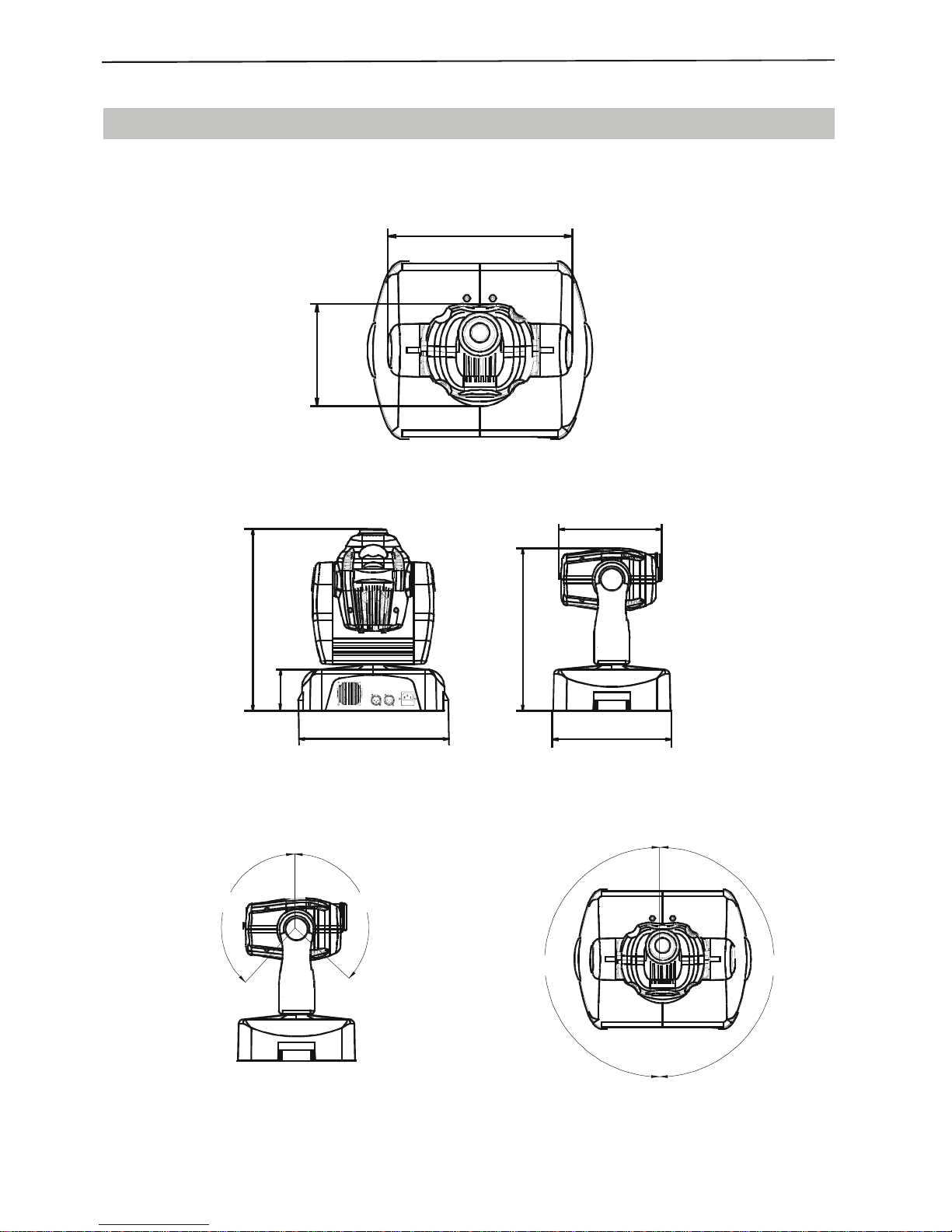
25cm
17cm
29cm
40cm
30cm
370cm
450cm
11cm
DIMENSIONS
¾
¾
¾
¾
¾
¾
¾
¾
¾
¾
¾
¾
¾
Don't touch the metal parts of light during devise is working.
Don't open the cover for there have no parts the user can repair.
Don't operate the light without lamps.
If the light equipment doesn't as light as before or there have some destroy with lens or
other parts, please contact the distributor in time.
When you want to retransfer the products, you had better use the original package to
shockproof.
Please make sure that the power already cut off before you install or repair products.
Do not look the lamp house directly to prevent hunting the eyes.
Keep the space between light equipment and combustible things more than 0.5 meter.
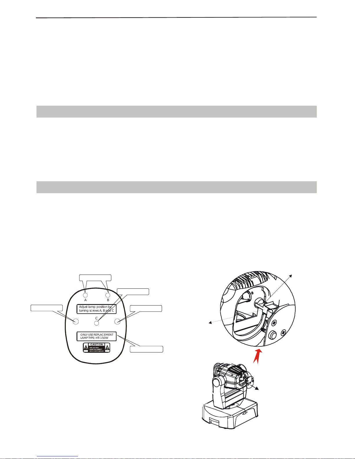
If you want to change the lamp, please make sure that the light is cool enough and the
power already cut off.
Unscrew the 2pcs M4 screws from the cover for change lamp at the back of light, then
take the cover for change lamp and lamp out of product together.
Insert the lamp into lamp holder.
Please don't use your hand to touch the mirror cover of lamp during installation. Please
use soft cloth to wipe clean if you touch it to provide the light effect.
Put in the cover for change lamp carefully and screw on 2pcs M4 screws.
WARNING
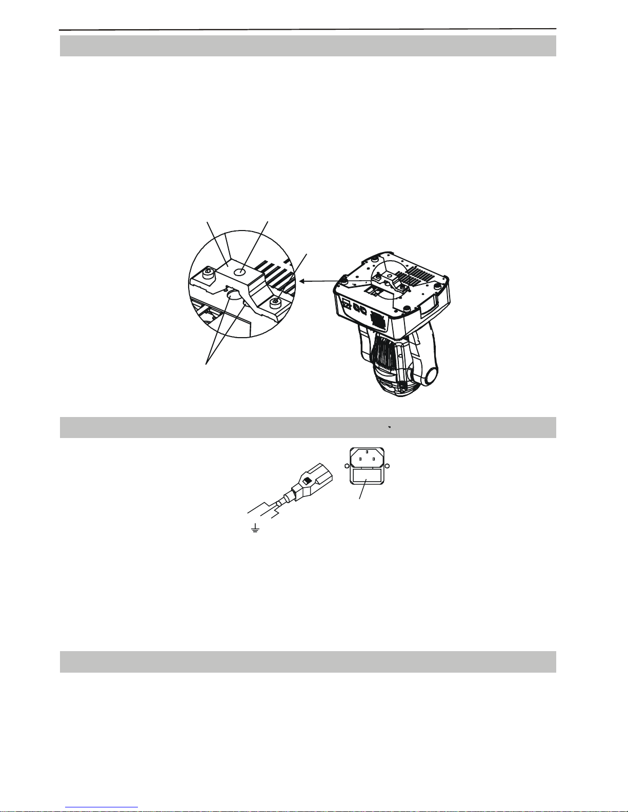
INSTALL THE LAMP
AB
C
Adjust lamp position by
turning screws A, B and C
ONLY USE REPLACEMENT
LAMPTYPE:HTI 150W
Bulb Faceplate
Pict.1 Pict.2
ACCESS SCREW
ACCESS SCREW
Adjust lamp position
Adjust lamp position
HTI 150W LAMP
LAMP HOLDER
.3.

OPEN BOX TO CHECK
INSTALLATION
ATTENTION
¾
¾
¾
¾
¾
¾
¾
¾
This product use new high temperature-resistance project plastic to make. It has a
b
eautiful surface to show the characteristic of new stage lights. Y It is made accord CE
standard. It accord with the international DMX512 agreement. Single or several can be
used at same time. It could be used in different place.
The product use HTI 150w discharge bulb and 10 different colors, 8 different affect
circumgyrate patterns. Strobe speed can be adjusted. Light touch control switch and
code display make operation easier. When you receive the product, take it gently and
check if there is problem which cause in transportation. At the same time please pay
attention to see if the following parts enclosed:
1 Power line
1 safty line
1 User manual
1. Please confirm whether the voltage you have is same as signed on the light before
install.
2. Installed by technician. It muse be placed safety and at best light angle.
3. Must keep space between light equipments and combustibles more than half a meter.
Keep space between light equipments and wall more than 0.15 meter.
4. The fans and vent-pipes should not be jammed by other equipment or decorate
materials.
5. There is a safty line connection hole at the bottom of light. Please use a safty line that
could stand 10 times of light's weight to drill through fuse line connection hole to help
install in safety view.
6. The light must be fixed installed.
7. In safety view please put earth line into the ground.
Please do not open the bottom cover by yourself without permission. Operate it accord
the user manual. Please call the technician in case the machine broken down.
Do not use it under the damp and rain.
Pay attention to prevent the light from strong bump.
Prevent the dust into the product
Keep the vent-pipe well while working.
Keep the plug insert well before put into power.
¾
¾
¾
¾
¾
Don't look the lamp directly to prevent make some destroy with eyes.
Don't light or extinguish frequently, otherwise the life span of the light tube will be
shortened.
In view of the special characters of lamp.
Don't touch the product and draw the power line if your hand is wet.
Keep the space between light equipments and the lighted things more than one meter.
.2
.
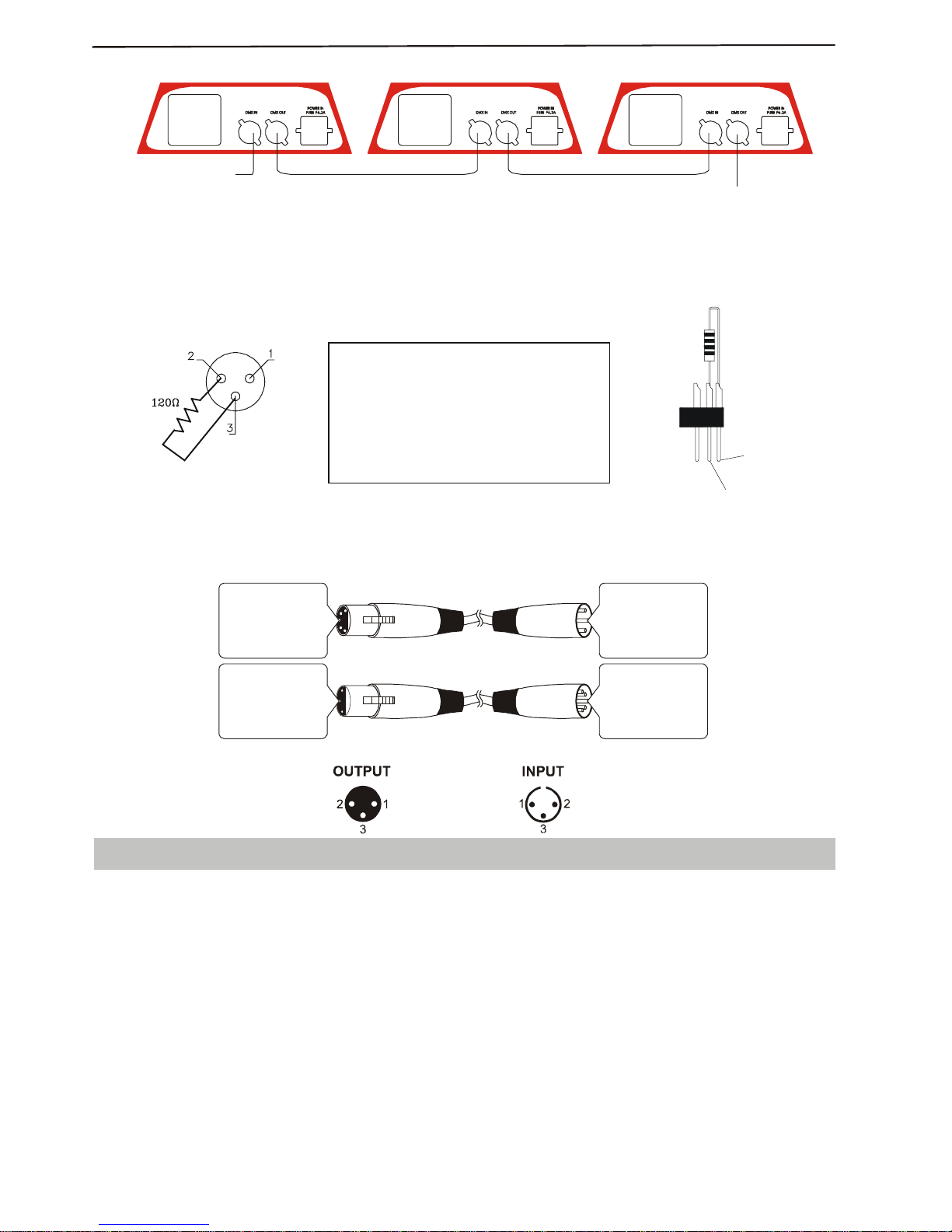
: Please remember the signal output of last machine must connect the attached circle
plug. The circle plug connect a 120 resistance between 2 feet and 3 feet canon plug. The
signal reflects phenomena can be avoided by using circle plug during DMX 512 signal
transfer.
The product use 3 feet XLR plug. If the controller you use is 5 feet XLR plug, you must
use a interchange line from 5 feet to 3 feet as following picture:
Note
Ω
¾
Light 1
Controlsingalinput
Outputandinput connecttogether Outputand inputconnecttogether
Lignt NLight 2
5Pins canon( )plug
Pin 1: GND(SCREEN)
Pin 2: Signal(-)
Pin 3: Signal(+)
Pin 4: N/C
Pin 5: N/C
3
Pin 1: GND(SCREEN)
Pin 2: Signal(-)
Pin 3: Signal(+)
Pins canon(socket)
5Pins canon(socket)
Pin 1: GND(SCREEN)
Pin 2: Signal(-)
Pin 3: Signal(+)
Pin 4: N/C
Pin 5: N/C
3plug
Pin 1: GND(SCREEN)
Pin 2: Signal(-)
Pin 3: Signal(+)
Pins canon( )
The transform of the controller line of 3 pins and 5 pins (plug and socket)
Pin 1: Screen
Pin 2: Signal -
Pin 3: Signal +
3 pins canon plug of DMX512 connect circuit
TERMINATOR
PIN 3
PIN 2
DMX TERMINATOR
CONNECTION
Connect a 120
Ω
(OHM) resistor across
p
ins 2 and 3 in an XLR plug and insert
into the DMX OUT socket on the last
unit in the chain.
INSTRUCTION & FUNCTION
¾
¾
¾
When you use the product first time or after change lamp, you can adjust 3pcs screws on
the cover for change lamp to change the station of lamp to get the best light effect.
The product use international standard DMX512 signal. Through use light touch switch
and code show screen you can easy to set DMX start channel and make function
operation.
Each equipment must be given a DMX start address so that the correct projector
responds to the correct control signals. This DMX start address is the channel number
from which the projector starts to listen to the digital control information being sent
out from the controller. The equipment has 7 channels, so set the No. 1 projector s
address 001, No. 2 projector s address 008, No. 3 projector s address 015, No. 4
projector s address 022, and so on.
“” `
``
`
.5
.
INSTALLING THE PROJECTOR
Bracket Fixing
Hole
M8x25
Bolt
P a s s safety fixing
through these holes
The projector should be mounted via its bracket using one M12 bolt.
The bracket itself attaches to the underside of the projector with two(2)M8x25 bolts
provided.
Always ensure that the projector is firmly anchored to avoid vibration and slipping whilst
operating.
Always ensure that the structure to which you are attaching the projector is secure and is
able to support a weight of 11Kg for each equipment.
For safety the projector should have a secondary fixing with a safety chain through the
holes on the underside of the unit.
WARNING: The projector should NEVER be lifted or carried by the yoke.
FUSE F6.3A/250V
FUSE HOLDER
LEN
L = BROWN
E = GREEN/YELLOW
N = BLUE
POWER SUPPLY MAINS
Use the plug provided to connect the mains power to the projector paying attention to the
voltage and frequency marked on the panel of the projector.
It is recommended that each projector is supplied separately so that they may be
individually switched on and off. IMPORTANT It is essential that each projector is
correctly earthed and that electrical installation conforms to all relevant standards. Power
consumption of the equipment is 280W.
CONTROL CONNECTIONS
¾
Connect the XLR-XLR control line from the DMX output of controller to DMX input of
each product and connect the DMX output of the first one to the DMX input of the
second one. Connect all products in this way. Then use the attached circle plug to
connect the signal output of last machine like picture show:
.4.

PANEL CONTROL
¾
¾
¾
¾
Press FUNC key continuous, the code screen will show the function operate code in
proper order. Every function operate code corresponding special function as following:
When the led screen shows the operation code which you need, press UP or DOWN
button, then the led screen will shows N (means NO) or Y(meansYES).
When the equipment reset itself, the led screen will shows , After reset, the led
screen shows address code. Press the ENTER button, then the this function
confirm(YES) or no valid(NO).
DMX signal ,sound ,automatic or master/slave working mode selection, the newest
selection valid.
888
Code Parallelism Function
X line reverse ,YES/NO
Set address code
Reset,YES/NO
DMX control
Auto-procedure
Sound control
Slave
1
2
3
4
Y line reverse ,YES/NO Enter Yes No
Enter Yes or No
Enter Yes (increase) or No decrease
Yes
→
→
→()
or
Parallelism Operate
5
000
001
002
003
.6.
¾
¾
The display shows the DMX start address after the projector is switched on (if you have
already set the DMX start address and saved it, the screen will display the last setting).
TO SET THE DMX STARTADDRESS :
Press the UP or DOWN buttons and the display will show the DMX start address.
Confirm your choice by pressing the ENTER button, this will save and set the DMX
start address. The display will show the latest setting each time the projector is powered
up. To control the projector with a DMX controller the DMX start address must be set.
Ensure that none of the Stand-Alone options are set or they will interfere with correct
DMX operation.
5
PAN
4
0-255
140-255
121-139
0-360
o
stop
7
speed
6
TILT
0-255
0-255
fast to slow
0-270
o
1
color
2
Gobos
4
3
Strobe
channel
5-120
0-4
241-255
151-240
86-150
0-85
200-255
180-199
200-255
160-179
140-159
120-139
100-119
80-99
60-79
40-59
20-39
0-19
stop
close light
open light
close light
orange
p
ale blue
green
rose red
pink
dark blue
p
ale green
yellow
Red
white
Function
224-255
192-223
160-191
128-159
96-12764-9632-630-31
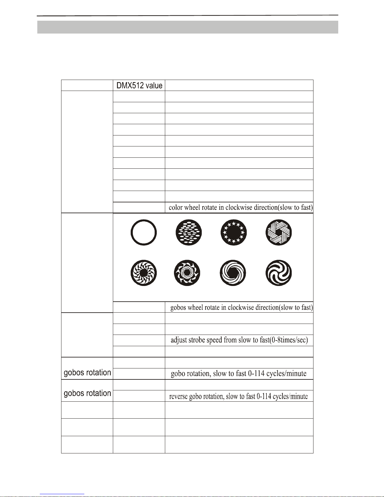
DMX 512 OPERATE MODE
¾
¾
If all channels are 255,the light equipment reset.
The product has 7 operate channels and use international standard DMX512 signal. The
details as following:
.7
.

Beampath:
SPECIFICATION
¾
¾
¾
¾
¾
¾
¾
¾
¾
¾
¾
¾
¾
¾
¾
Rated voltage: AC220~240V, 50/60Hz
Rated power: 200W
Bulb: HTI 150W
Electric strength: 1.5kv
Insulation resistance:>2M
Channel: 7 channels
Signal: DMX512
Control mode: DMX512 controller
Color: 9 colors + white, rainbow effect
Design: 7 different gobos + white beam, rainbow effect
Strobe: 0-8 times/SEC, adjustable
Rotation angle: horizontal:370 , vertical:265
Size: 370 275 375mm
Net weight: 11kg
Other effect: auto cut off while high temperature, focus adjustable, reset without any
sound.
Ω
××
oo
6m
4m
2m
0m
2m
4m
6m
5m
3m
1m
1m
3m
5m
0m 5m
BEAM DIAMETER
.8.
13

.9
.
ELECTRICALDIAGRAM

MAINTAIN
ANNOUNCEMENT
¾
¾
¾
¾
The optical lens and illuminators must clean regular to protect a better effect. You can
clean them accord the light's operate times and the using situation. Use soft cloth and
original glass cleaner to clean. You'd better clean exterior optical system every 20 days
and inside optical system every 60 days at least.
Do not use organic solvent such as alcohol to clean the cover of light.
When we delivery the goods out of factory, it's function is good and package is well. All
users must obey all noted attentions and operate rules. We won't serve free of charge
repair if the destroy be caused by your own wrong operate. All the problems which be
caused by not operate accord the user manual also not the duty of distributor.
We won't inform again if there have any more changes of user manual.
.10
.
FAULTY
PHENOMENON FAULTYANALYSIS FAULTY PART
PART No.
Power plug loose
Whole light cann't
work
No light from bulb
Power fuse faulty
Reach the lifespan or bed
Temperature switch faulty
Ballast faulty
Plug cable for PC
T3.15A 5*20DIA
27-00-0005-01
09-00-3151-00
07-07-0150-00
11-10-0010-00
08-07-0013-00
06-03-Z009-00
quality of bulb
Trigger faulty
150w ballast
10A105C temperature switch
Electronictrigger
HTI 150w
Bulb light but
Complete motor can
Not work. No light in
The screen and fans
can not work
Transformer faulty 150W/10.8V/24Vtransformer
Main board faulty LT-150 main board
06-00-B056-00
26-2A-LT150DRV3-00
Bulb lighting ,whole
light normal but fans
cannot work
Fan on head of light faulty
Fan on bottom of light faulty
80*80*25 DC12V/0.4A
60*60*25 DC 12V/0.4A
16-00-0007-01
16-00-0011-00
Lamp holder faulty 150 lamp holder 07-11-0014-00
BULBAND FANS NORMAL
Complete light
reseat but can
not be controlled
Complete light
can not reposition Main board faulty
whether the signal cable
good or not
LT-150 main board
LT-150 show board
5 meters cable sets
Gobos not rotatewheel can
Strobe can not work
Can not adjust pan
Can not adjust tilt
Gobos wheel can
not work Motor for Gobos faulty
Motor for rotate faulty
Motor for strobe faulty
Motor for pan faulty
Motor for tilt faulty
Fourlines step motor
Fourlines step motor
Fourlines step motor
Fourlines step motor
Fourlines step motor
Fourlines step motor
15-00-0007-00
15-00-0006-00
15-00-0007-00
15-00-0007-00
15-00-0005-00
15-00-0004-00
15-00-0016-00
main
board
can
not
work
Motor for colorwheel faulty
26-2A-LT150DRV3-00
26-2A-LT300DI-00Show board faulty
27-04-0010-00
Fourlines step motor
COMMON FAULTYMAINTAIN
Color not rotatewheel can
Table of contents
Other SilverStar Light Fixture manuals

 Laser User manual")
Popular Light Fixture manuals by other brands


Exitronix
Exitronix Mesa Series installation instructions

Rush
Rush MH 2 Wash user manual

Dialighting
Dialighting IS200-MH user manual

Cantar Pool Products
Cantar Pool Products Full Moon Owner's Manual & Installation Instructions

ARRI
ARRI Claypaky XTYLOS AQUA User information

Robe
Robe Color Spot 575AT user manual