Sim2 RTX 55 Operating manual

USER AND INSTALLATION
MANUAL
ENGLISH
RTX 45-55

IMPORTANT SAFETY INSTRUCTIONS
!
CAUTION
ELECTRIC SHOCK HAZARD
DO NOT OPEN
For the DigiOptical Image Processor use exclusively the
power supply unit provided or an alternative power supply
unit expressly approved by SIM2.
•Beware of power supply cables.
Positionthepowersupplycablessothattheydonotconstitute
an obstruction.
Position the power supply cables where they cannot be
reached by children.
Install the units as close as possible to the wall electrical
socket outlet. Do not tread on the power cables, make sure
that they are not tangled or pulled; do not expose the power
cables to heat sources; make sure that the power cables do
not become knotted or kinked. If the power cables become
damaged, stop using the system and request the assistance
of an authorised technician.
•Disconnect the apparatus from the mains power supply
in the event of electrical storms and when not in use.
To avoid damage that could be caused by lightning striking
in the vicinity of your home, disconnect the units in the event
of electrical storms or when the system will remain unused
for prolonged periods.
•Avoid contact with liquids and exposure to humidity.
Do not use the units near water (sinks, tanks, etc.); do not
place objects containing liquids on top of or near the units
and do not expose them to rain, humidity, dripping water or
spray;donot use water orliquiddetergents to clean theunits.
•Prevent the units from overheating.
Donotobstructventilationopenings.Donotplacetheunitsnear
heat sources such as heaters, radiators or other devices that
generateheat(includingamplifiers).Donotpositiontheunitsin
confined,poorly ventilated places (bookcase, shelves, etc.).
•Do not expose the eyes to the intense light emitted by
the lamp.
Neverlookdirectlyatthelamp through the ventilation opening
when the unit is switched on.
Risk of eyesight impairment. Ensure also that children do
not look directly at the lamp.
•Position the unit on a stable surface.
To avoid serious injury to persons and damage to property,
make sure the units are placed on a level, flat and stable
surface from which they cannot fall, tip over or slide. Pay
special attention if the units are placed on a trolley so that
they can be moved around. Ensure that the units are not
subjected to impact.
•Do not insert objects through the units’ openings.
Make sure that no objects are inserted inside the units. If this
should occur, disconnect the unit from the power supply
immediately and call an authorised technician.
This symbol indicates the possible electric shock
hazardassociated with uninsulated livecomponents
in the interior of the unit.
This symbol indicates the presence of important
instructions regarding use and maintenance of the
product.
•Read this manual carefully and keep it in a safe place for
future consultation.
This manual contains important information on how to install
andusethisequipmentcorrectly. Before using the equipment,
read the safety prescriptions and instructions carefully. Keep
the manual for future consultation.
•Do not touch internal parts of the units.
The units contain electrical parts carrying high voltages and
operating at high temperatures. Do not remove the cover
fromtheunits,referto qualified service personnel for allrepair
and maintenance requirements.
The warranty will be automatically invalidated if the cover is
removed from the units.
•Power supply disconnect device.
The device for disconnecting the units from the mains power
supply is constituted by the power cable plug. Ensure that
thepower cable plugsand the electricalmains socket outlets
are easily accessible during installation operations. To
disconnect the units from the electric power supply, pull the
plugto remove it fromthe socket outlet. Donot pull the power
cable.
•Use only the specified type of mains power supply.
Connect the units to a mains electrical supply with rated
voltage of between 100-240 VAC, 50/60 Hz and equipped
with a protective earth connection. If you are unsure of the
type of mains power supply in your home, consult a qualified
electrician.
Ensure that the power draw of the units is commensurate
with the rating of the electrical socket outlets and any
extension cables that are used.
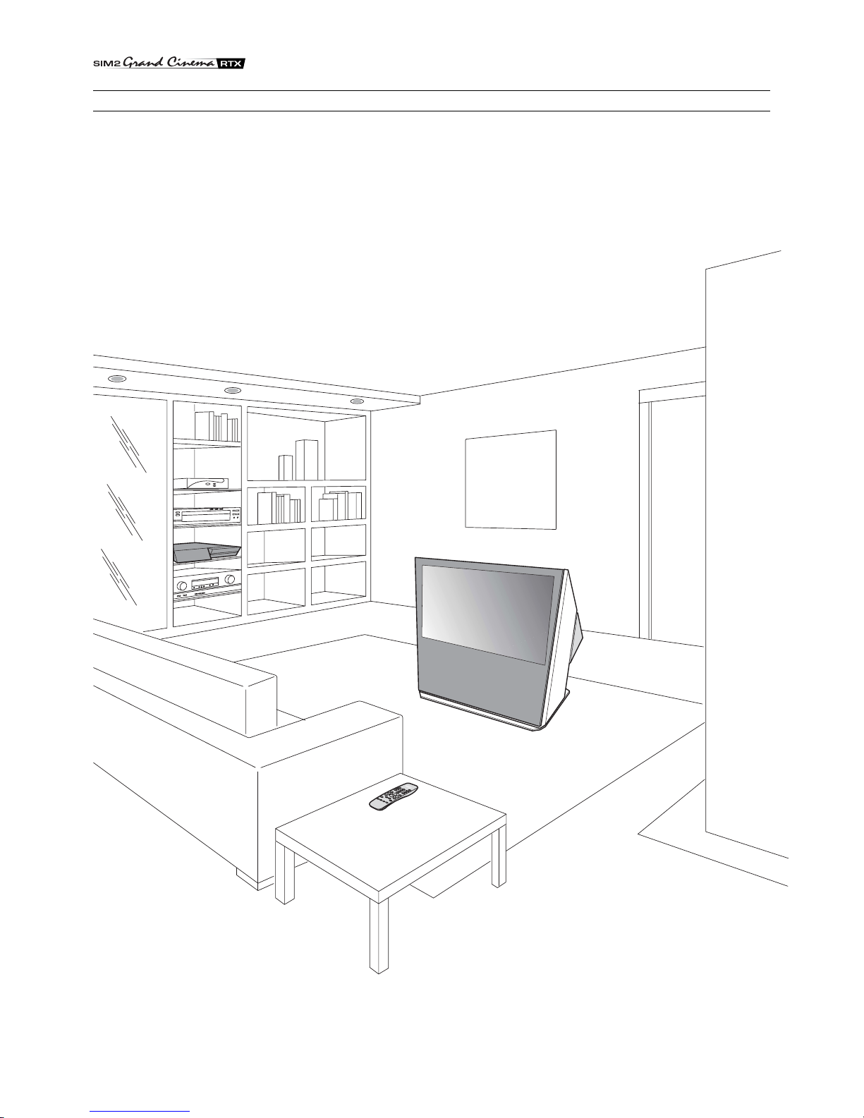
The RTX system consists of two parts connected by a fibre
opticcable:the DigiOptical Image Processorandthe Display.
In this manual references to the “unit” refer to one of the two
units that make up the system.
•Federal Communication Commission (FCC Statement).
This equipment has been tested and found to comply with the
limits for a Class B digital device, pursuant to Part 15 of the FCC
rules.
These limits are designed to provide reasonable protection
against harmful interference when the equipment is used in a
commercial environment. This equipment generates, uses and
canradiateradio frequency energy and, if not installed and used
in accordance with the instruction manual, may cause harmful
interference to radio communications. However, there is no
guarantee that interference will not occur in a particular
installation. If this equipment does cause harmful interference to
radio or television reception, which can be determinated by
turning the equipment off and on, the user is encuraged to try to
correctthe interferenceby one ormore of thefollowing measures:
- Reorient or relocate the receiving antenna
- Increase the separation between the equipment and receiver.
- Connect the equipment into an outlet on a circuit different from
that to which the receiver is connected.
-Consult the dealer or an experienced radio/TV technician for help.
•For customers in Canada
ThisClass B digital apparatus complies with Canadian ICES-003.
•For customers in the United Kingdom•
ATTENTION: This apparatus must be earthed.
The wires in this mains lead are coloured in accordance with the
following code:
Green-and-Yellow: Earth
Blue: Neutral
Brown: Live
As the colours of the wires in the mains lead of this apparatus
may not correspond with the coloured markings identifying the
terminals in your plug proceed as follows:
The wire which is coloured green-and-yellow must be connected
tothe terminal in the plug which is marked by the letter E or by the
safety earth symbol or coloured green or greenand- yellow.
Thewire which is coloured blue mustbeconnected to the terminal
whichis marked with theletterN or coloured black.The wire which
is coloured brown must be connected to the terminal which is
marked with the letter L or coloured red.

TABLE OF CONTENTS
INTRODUCTION .......................................................................................................................4
1 INSTALLATION.............................................................................................. 6
CONNECTING THE TWO UNITS..............................................................................................6
CONNECTING THE VIDEO SOURCES....................................................................................7
Video .................................................................................................................................7
S-Video ................................................................................................................................7
COMPONENT/RGBS ..........................................................................................................7
Graphics RGB......................................................................................................................9
DVI-D .................................................................................................................................9
RS232 Control .....................................................................................................................9
Fibre optic link......................................................................................................................9
2 OPERATION ................................................................................................ 10
SWITCHING ON AND OFF .....................................................................................................10
KEYPAD .................................................................................................................................. 11
REMOTE CONTROL............................................................................................................... 11
ON SCREEN MENUS .............................................................................................................12
Inputs ...............................................................................................................................12
Main Menu .........................................................................................................................13
Picture ...............................................................................................................................13
Image ...............................................................................................................................14
Setup ...............................................................................................................................15
Info ...............................................................................................................................15
Quick Menus ......................................................................................................................15
Messages ..........................................................................................................................15
MAINTENANCEAND TROUBLESHOOTING .........................................................................16
Maintenance and cleaning.................................................................................................16
Troubleshooting guide........................................................................................................16
3ADDITIONAL INFORMATION ..................................................................... 18
TECHNICAL SPECIFICATIONS..............................................................................................18
DIMENSIONS..........................................................................................................................20
ON SCREEN MENU LAYOUT .................................................................................................21

4
INTRODUCTION
Congratulationson your choiceof the SIM2Grand Cinema RTX
system!
The RTX system combines the signal processing capabilities
of the DigiOptical Image Processor with the high fidelity
reproduction of the DLP™ technology Display by linking the
two units via a fibre optic cable.

5
DLP and DMD are registered trademarks of Texas Instruments.
DCDi is a registered trademark of Faroudja, a division of Genesis Microchip, Inc.
TheDigiOptical Image Processor,whichshouldbeideallylocated
closetothesignalsources,supportsandprocessesawiderange
of video signals, transmitting them to the display by means of a
fibre optic link cable.
Thelarge number of inputs available(2 Composite Videoinputs,
2 S-Video inputs, up to 4 Component or RGB inputs, 2 graphic
RGB inputs and 1 DVI-D input) ensures the system supports a
widevariety of analogue and digital sources: DVD players,VCRs,
satellite and terrestrial receivers, computers, game consoles,
video cameras, etc.
The signal processing capabilities of the Image Processor
ensure optimum reproduction of a broad range of input signals,
from interlaced video to high definition and graphics.
Conversion of interlaced video signals to progressive signals
by means of prestigious DCDi™ technology produces fluid,
natural, images free of flicker and stairstepping artefacts.
Faithful reproduction of signals at higher resolutions (such as
high definition video and graphics) occurs without loss of
information or reduction of image sharpness thanks to the
processor’s high pixel rate signal acquisition capabilities.
Adaptationofthe input signal resolutionto the Display resolution
occurs without alterations of image quality, in accordance with
an ample choice of aspect ratios, including several definable by
the user.
Allimage adjustments can be performed with theremote control
with the aid of the On Screen Display; alternatively, the unit can
be controlled by from a home automation system through the
serial port.
The Display, with its elegant and original design, produces an
imageusingtheverylatestTexas Instruments DLP™technology
(1280x720 pixel DMD™ panel with 12°technology), a
proprietarydust-sealedopticalsystem,anewsix-segmentcolour
wheelandanew type of Fresnel lens.All these features combine
to provide a top quality image, with definition, sharpness,
colorimetry and contrast on a par with the famous frontal
projectors in SIM2’s Grand Cinema line.
The two units are connected via a three-core fibre optic cable
for transmission of the digital signal from the DigiOptical Image
Processor to the Display and control signals in both directions.
Transmission occurs without interference or attenuation over
distances of up to 500 m.
Moreover, the flexibility and small size of the cable allow the
maximum freedom when installing the system in your home.

6
CONNECTING THE TWO UNITS
The RTX system consists of two separate units (the DigiOptical
Image Processor and the Display), each of which is equipped
with a power cable; the two units are interconnected by a 20 m
fibre optic cable.
The ideal location for the DigiOptical Image Processor is on a
cabinetshelf or on a rack (dimensions compatible with a standard
19" rack). Make sure that the support surface is stable and that
the unit has sufficient space around it for ventilation purposes
(at least 3 cm).
The unit is connected to the mains via an external power supply
unit with an output of +7 Vdc; the unit’s main power switch is on
the power supply unit.
Display
Alimentatore
DigiOptical
Image Processor
Remote Control
1.5 V AAA-
type batteries
Power cables
Europe, UK, US (x2)
DigiOptical
Image Processor
Three-core
fibre optic cable
Instruction
Manual
DIGIOPTICALIMAGEPROCESSOR
O
I
DigiOptical Image
Processor power supply unit
1 INSTALLATION
SIM2’s RTX system is made up of the following components
(Fig.1):
•Display
•DigiOptical Image Processor
•remote control
•DigiOptical Image Processor power supply unit
•three power cables for the Display
•three power cables for the DigiOptical Image Processor
•triple fibre optic cable for linking the
DigiOptical Image Processor and the Display
•four 1.5 V AAA-type batteries for the remote control
•User and installation manual
If any accessories are missing, contact your Dealer as soon as
possible.
Connect the power supply unit output cable to the POWER
socket located on the rear panel (Fig. 4).
Use exclusively the power supply unit provided with the system
oran alternative power supplyunitexpressly approved bySIM2.
The Display is designed to stand on the floor. Place the Display
onaflat,levelsurfacewhereithassufficientspace for ventilation;
to prevent glare and reflections, avoid places exposed to direct
sunlight or intense light sources.
The mains power input socket and the power switch are both
located on the rear panel.
Adjust the rear feet to obtain the optimum viewing angle in
accordance with the distance and height of the viewing position
in front of the Display (Fig. 2).
The system can be fully controlled using the supplied IR
Fig.1
(infrared)remote control handset.There is asingleremotecontrol
for both the DigiOptical Image Processor and the Display; the
remote control can be directed towards either unit since they
are both equipped with an IR sensor.
The connection between the two units is made with a single
cable containing three fibre optic cables each terminating in an
LCconnector.Thestandard cable length of 20 m willbesufficient
for most installation requirements.
Fig.2
Cavo
Fibra
Ferrule
Connettore
Tappo di
protezione
Punto di
sfiocco
Protective cap
Separation point
Cable
Connector
Fibre
Fig.3

7
CONNECTING THE VIDEO SOURCES
Connect the cables from the video sources, the serial cable
from the external control unit and the optical fibre cables for
connection to the Display, to the rear panel of the DigiOptical
Image Processor.
To obtain the best performance from the RTX system, connect
the various signal sources using good quality cables designed
for video applications (rated impedance 75 Ω).
Ensure that:
•the cables are routed in such a way that they do not present
an obstruction to people moving around the room;
•the connectors are inserted carefully to avoid damaging the
pins;
•the cables are not twisted or crushed;
•when disconnecting the cables the connectors are not
violently pulled out of the sockets on the various units.
Video sources (television receivers, VCRs, DVD players, etc.)
often feature several outputs. To obtain the best performance
from your system, carefully choose which output to use.
Generally, the type of signal offering the best picture quality is
DVI-D,followed by RGB, Components, S-Video and Composite
Video, in that order.
However, the RTX system is equipped with an excellent Video
Decoder and Deinterlacer and therefore even inferior quality
signals will produce high quality results.
Table 2 shows the types of signals usually available for the most
common types of video sources and the corresponding input
connectors to use on the DigiOptical Image Processor.
VIDEO
These inputs should be connected to a Composite Video signal
(CVBS) by means of a cable with an RCA connector.
The connector on the source is usually yellow and is frequently
labelled VIDEO.
Although other types of signals are preferable (since they allow
betterpicturequality),thisisstillthemostcommontypeof output,
andnearlyalltelevisionreceivers,video-recorders,DVDplayers,
video cameras, etc., are equipped with CVBS outputs.
S-VIDEO
These inputs should be connected to an S-Video signal by
means of a cable with a 4-pin mini-DIN type connector.
The corresponding output on the source can be identified by
the wording S-VIDEO or Y/C.
Almost as widespread as Composite Video, S-VIDEO is
preferable because it offers a clearer and sharper picture.
COMPONENT / RGBS
These inputs are composed of three sets of 5 RCA connectors
(5,6,7) and a set of 5 BNC connectors (8).
Each set of connectors is suitable for RGB and Component
signals.
RGBsignalscanhavethefollowing synchronisations: composite
sync on the green signal (RGsB), H+V Composite Sync, or se-
parate H/V Sync.
Connect the R, G, B outputs of the source to the respective R,
G,B inputs of theDigiOptical Image Processor (payingattention
not to invert the positions) and any synchronisation signals to
the HV input or the H and V inputs. When connecting the three
sets of RCA connectors use the colours as a guide: connector
R is red, G is green, B is blue, H/HV is white and V is black.
By using a suitable SCARTto RCA(or BNC) connector adapter
cable, an RGB video signal from a source equipped with an
SCART connector can be connected to this input.
Componentsignals are connected toinputsY,Cr and Cb, taking
care to observe the correspondence with the outputs on the
source.
Since the latter can be labelled in various ways, refer toTable 1
to establish the correspondence between the various signals.
The connector colours can also be of help, as shown in the
table.
During installation of the fibre optic cable:
•The individual optical cables are delicate: always handle the
maincablewithout touching the individualoptical cables (Fig.
3). Never pull the individual optical cables or connectors; if
necessary, you may pull the main three-core cable.
•Only remove the cap protecting the connector ferrule
immediately before inserting the connector; if the ferrule is
allowed to come into contact with foreign material it may be
damaged, making the connector unusable.
•Take particular care when inserting fibre optic connectors in
their respective sockets on the rear panel of the DigiOptical
Image Processor and the rear panel of the Display (Fig. 5).
•Make sure that the single optical cables are not switched:
the numbers on the cables must match the numbers on the
connectors.
•Check that the connectors are correctly inserted.
•Use the cable clamps on the rear panel of the Display to
protect the connectors from traction and leverage.
•Make sure that the cable does not constitute an obstacle for
persons moving around the room.
•Takecare not to createknotsinthecable;the minimum radius
of bends in the cable is 2 cm.
•Prevent the cable from pulling and mechanical stress: this
could cause the connectors to be pulled out and damaged.
DigiOptical
Image Processor
Connector
Y (green) Y
Cr (red) P
Cb (blue)
R
Y
R-Y
Y
V
P
B
B-Y U
Video signal
source connector
Table 1

8
Source Signal DigiOptical Image Processor
Connector Input
Television receiver from Antenna,
Satellite or Cable (Analogue or Digital) Composite video
S-Video
Components
RGB
Video
S-Video
Component/RGBS
Component/RGBS
1 2
3 4
5 6 7 8
5 6 7 8
DVD player Composite video
S-Video
Components
RGB
Video
S-Video
Component/RGBS
Component/RGBS
1 2
3 4
5 6 7 8
5 6 7 8
Videorecorder Composite video
S-Video
Components
RGB
Video
S-Video
Component/RGBS
Component/RGBS
1 2
3 4
5 6 7 8
5 6 7 8
HDTV receiver Components
RGB Component/RGBS
Graphics RGB
5 6 7 8
910
910
910
Game console Composite video
S-Video
Components
RGB
RGB
Video
S-Video
Component/RGBS
Component/RGBS
Graphics RGB
1 2
3 4
5 6 7 8
5 6 7 8
Video camera Composite video
S-Video Video
S-Video
1 2
3 4
Computer RGB
DVI Graphics RGB
DVI-D 11
Table 2
Fig.4
DCIN
12VOUTVIDEOS-VIDEOCOMPONENT/RGBS
COMPONENT / RGBS
R/CrV
G/YB/CbH/HV
R/CrV
G/YB/CbH/HV
R/CrV
G/YB/CbH/HV
R/CrV
G/YB/CbH/HV
GRAPHICSRGB
DVI-D
1
2
3
4
5
6
7
811
CLASS1LASERPRODUCT
9
10
123-NOT
USED
CONTROL(RS232)
POWER
2
3
1
VIDEO
POWER
S-VIDEO
GRAPHICS RGB
DVI-D
CONTROL (RS 232)
OPTICAL FIBER LINK
1 2
3 4
9
10
5 6 7 8
11
Source
Television receiver
from Aerial, Satellite or
Cable (Analogue or Digital)
DVD player
Video recorder
Video camera
Game console
Television receiver from
Aerial, Satellite or
Cable (Analogue or Digital)
DVD player
Video recorder
Video camera
Game console
Television receiver from
Aerial, Satellite or
Cable (Analogue or Digital)
HDTV receiver
DVD player
Video recorder
Game console
Television receiver from
Aerial, Satellite or
Cable (Analogue or Digital)
HDTV receiver
DVD player
Video recorder
Game console
HDTV receiver
Game console
Computer
Computer
Home
automation
system
Computer
Display
RTX

9
The video signals that can be connected to this input can have
horizontal scanning frequencies of 15 kHz (standard video
resolution), 32 kHz, or higher (progressive scanning video, high
definition video).
Some sources provide the facility to choose between a
progressive signal or an interlaced signal.Although in general a
progressive signal is higher quality than an interlaced signal, it
is often preferable to perform the deinterlacing operation on the
RTXsystem ratherthan on thesource because theRTXsystem
isequipped with Faroudja’ssophisticated directionalcorrelation
deinterlacing technology (DCDi™).
Progressivesignalsusually provide better quality thaninterlaced
signals, but if the source features both progressive and
deinterlaced signal outputs it is good practice to compare the
quality of the pictures reproduced by the RTX system in the two
cases: deinterlacing performed by the RTX system (thanks to
Faroudja DCDi™ technology) is often more effective than that
performed at the source (typically a DVD player).
RGB GRAPHICS
Thisinput should be connectedto an RGB-type videoor graphic
signal using a cable with a DB15HD type connector.
Thesignalsource device (typically a personalcomputerorgame
console) must be able to provide separate H/V synchronisation
orcompositeH+Vsynchronisation or composite synchronisation
on the green signal (RGsB).
The video or graphic signals that can be connected to this input
can have horizontal scan frequencies (H-sync) of between 15
and 110 kHz and a vertical frequency (V-sync) of between 40
and 100 Hz. Image resolution can vary between 640x480 and
1600x1200 pixels (VGA, SVGA, XGA, SXGA, UXGA).
3
12
3
3
Protective
cap
Fig.5
DVI-D
If your source is equipped with this type of output (increasingly
present on the latest PCs) you can take advantage of the better
picture quality by using the DVI-D input.
CONTROL (RS232)
The system can be controlled via a personal computer or home
automation systems by means of the serial port: simply connect
this input via a serial cable from an RS232 serial port. On
request, SIM2 will send you a document containing the serial
port settings and the list of main commands.
FIBRE OPTIC LINK
After removing the protective caps from the fibre optic cable
connectors and the panel connectors, insert the fibre optic
connectors carefully, matching the numbers shown on each
element. Be very careful when handling optical fibres cable and
connectors.

10
SWITCHING ON AND OFF
2 OPERATION
will operate but it may be unable to read certain input signals
correctly.
Switching on the system:
• from the remote control (keys 0-9)
• from the Display keypad (keys and ).
Typically, the picture will appear after 15-20 seconds. Pressing
a key from 1-9 on the remote control selects the corresponding
The RTX system consists of the Display and the DigiOptical
Image Processor (which is also the system control centre). The
DigiOptical Image Processor sends commands to the Display
and receives operating status information from the Display and
functioncommands from the user.The system can becontrolled
from either the remote control (via the infrared sensors on the
DigiOptical Image Processor and on the Display) or the keypad
located on the top of the Display.
The two units have separate power supplies however: after
connecting the unit to the electrical mains supply, set the two
power switches to “I”; the DigiOptical Image Processor power
switch is located on the external power supply unit (Fig. 6a),
while the Display switch is on the Display rear panel (Fig. 6b).
Off
Initialisation
Status
DigiOptical Image
Processor Display
Green LED Blue LED Front LED
Keyboardpad
Stand-by
On
Cooling
Optical link not active
Caution
Error
: Off : On : Flashing : Insignificant
--
--
-
-
-
--
E
SC
MEN
U
AU
T
O
0
E
SC
MEN
U
AU
T
O
Table 3
input; pressing 0 selects the input active at the time the system
was last switched off.
If the system is switched on very soon after it was last switched
off, the lamp may fail to come on because it is too hot. In this
case just wait a few minutes to allow the lamp to cool.
Switching the system off :
• from the remote control ( key)
• from the Display keypad ( key).
If you wish to power off the system completely, wait at least one
minute in stand-by before setting the mains power switches on
the units to the “O” position or disconnecting the power supply
Fig.7
Fig.8
O
I
Fig.6bFig.6a
Aftera few seconds (system initialisation interval), the DigiOptical
Image Processor and the Display assume stand-by mode.
System status information is provided by two LEDs (green and
blue) on the front panel of the DigiOptical Image Processor, a
blue LED on the front of the Display, and the keypad status (off
or illuminated).
Significant status signals are given in Table 3.
If the “No optical link” or “Error” signals are active the system
cannot be operated; if the “Warning” signal is active the system

11
E
SC
MEN
U
AU
T
O
Navigate through and make adjustments
to the on screen menus.
switches on from stand-by and calls
the Input Selection menu.
(if pressed in the absence of the On
ScreenDisplay) callsthe INFOinformation
window
MENU
Activates the On Screen Display menus.
Navigatesmenupages.
ESC
Deactivates the On Screen
Display
AUTO
Selects Auto Adjust (automatic
optimisation of the displayed image).
KEYPAD
+-
+-
+
-
+
-Four 1.5V
AAA-type
batteries
The keypad on the back of the Display features eight keys
providing the facility for complete control of the apparatus
even without the remote control.
REMOTE CONTROL
The remote control transmits commands to the system by
infrared signals.
There are two infrared sensors, one at the front of the Display
and one on the front panel of the DigiOptical Image
Processor.
Avoid placing obstructions between the remote control and
the infrared sensor at the front of the projector; this will impair
the remote control performance.
The remote control requires four 1.5V AAA alkaline batteries.
Insert the batteries, taking care to match the polarity, as
indicated in the battery compartment in the handset (Fig. 10).
Change the remote control batteries if you experience
difficulty in transmitting commands to the system.
Remove batteries from the remote control if it is to remain
unused for a long period of time to avoid the risk of potentially
harmful chemical leaks.
Switches system to stand-by.
cables.This is to allow the fans in the Display unit sufficienttime
to cool the lamp.
Fig.9
Fig.10

12
Not active
in this model.
Not active
in this model.
MENU
Activates the On Screen Display
menus and allows navigation
though the various pages.
FREEZE
Freezes a
moving picture.
Not active
in this model.
STAND-BY
Switches system to stand-by.
KEYS 0-9
Switch system on from
stand-by and allow
direct source selection.
ESCAPE
Deactivates the On Screen Display.
MENU
Activates the On Screen Display
menus and allows navigation
though the various pages.
INFO
Displays selected source
information and system status.
VCR
Activates a filter to improve
video recorder signal quality.
ASPECT
Selects picture aspect ratio.
INPUT
Displays the Source
Selection menu.
Navigate through
the On Screen Display and make
adjustments to the parameters.
activate quick menus.
AUTO
Selects Auto Adjust
(automatic optimisation
of the displayed image).
Not active
in this model.
+
-
ON SCREEN MENU
All system functions can be activated from the keypad or remo-
te control with the aid of a practical and comprehensive system
of on screen menus.
INPUTS
The input selection menu (Inputs) is called by pressing 0 on the
remote control and, when no other menu is displayed, using the
and keys on the keypad. To select an input, scroll the list
with the and keys until the desired input is highlighted,
then press .
Alternatively, press the corresponding numerical key (1...11) on
the remote control (for numbers 10 and 11 press keys 1 and 0
(10) or 1 and 1 (11) in rapid succession).
Display of the input selection menu is terminated
Inputs
2 Video
3 S-Video
9 RGB Graphic
10
11
4 S-Video
5 YCrCb 32kHz
6 RGBS 15kHz
7 YCrCb 32kHz
8 YCrCb 15kHz
1 Video
RGB Graphic
DVI-D
Inputs
2 Video
3 S-Video
9 RGB Graphic
10
11
4 S-Video
5
6
7
8
1 Video
YCrCb 15kHz
YCrCb 32kHz
RGBS 15kHz
RGBS 32kHz
DVI-D
RGB Graphic
Fig.11
Fig.12a Fig. 12b

13
bypressingthe ESC key,orwhen the time allowed fordisplaying
the on-screen menu has lapsed (set in the Set-up Menu).
Inputs 5, 6, 7 and 8 can receive RGB and YCrCb signals, at 15
kHz, 32 kHz or higher. The association between the input and
thetype of signal ismade from thepull-down menu that appears
on the right of the < symbol after pressing the < key (Fig. 12b).
After selecting the source signal (by means of the and
keys),pressMENU+/MENU - to confirmandclose the pull-down
menu; the value you have just set will be displayed on the right
of the < symbol.
As with the other inputs, you can now select the input just set by
pressing the > key.
During the short time it takes to find the signal, a box appears
showing the signal requested. As soon as the signal is shown
in the box additional information is displayed concerning the
video standard (for video signals) or resolution (for graphic
signals), and format.
MAIN MENU
To access the main menu of the On Screen Display press the
MENU key on the keypad or the MENU+ or MENU- key on the
remote control.
The main menu is divided into three windows, PICTURE,
IMAGE and SETUP, in which the various adjustments are
grouped according to the frequency of use. Use and
to select the line corresponding to the adjustment you wish to
make (Fig. 13).
Picture Image Setup
Contrast
Colour
Tint
Sharpness
Filter
Cinema Mode
Video Type
50
50
50
3
2Off
Normal Auto
VCR
Brightness 60
Colour Temperature
Gamma Correction
Position
Y/C Delay
Magnification 1
Aspect
Picture Image Setup
Colour Temperature
Gamma Correction
Position
Y/C Delay
Magnification 1
Aspect Normal
Anamorphic
Letterbox
Panoramic
Pixel to pixel
User 1
User 2
User 3
Picture Image Setup
The various menus only offer the relevant adjustments in
accordance with the type of input signal displayed (e.g. certain
typical adjustments for video signals, not necessary for graphic
signals, do not appear on the menus, and vice versa).
Some adjustments (e.g. BRIGHTNESS and CONTRAST) are
associated with a numerical value that can be varied within the
set limits using the keys / .
For others (e.g. VIDEO TYPE) you can choose between two
options presented on the same line (and selectable using the
keys / ).
Otheradjustments(marked by the <symbol)provide submenus,
which appear as a superimposed window in which the selection
is made with the / keys (Fig. 14).
These submenus are accessed by pressing the < key, while
exit and return to the upper level occurs by pressing MENU+/-.
Press ESC on the remote control or keypad to interrupt the
menu display or wait for it to disappear automatically after the
number of seconds set on the SET-UP page.
PICTURE
This menu features the adjustments related to picture quality.
Adjustments that are not available for a given input do not
appear on the menu. Table 4 summarises the adjustments
available for each input. For a complete overview of the on-
screen menus, consult the ‘On screen menu layout’ in the
“Additional Information” section.
BRIGHTNESS
Use this control to adjust the image’s black level without
affecting white areas. Increasing the value will give more detail
in darker parts of the picture. For correct adjustment it may pro-
ve useful to display the signal relative to the grey scale within
which the black level and the level immediately above it must
be separately identifiable.Alternatively use a scene composed
of black objects alongside other dark coloured objects.
CONTRAST
Usethiscontrolto adjust the image’sblack level without affecting
white areas.
To ensure correct adjustment, it may prove useful to display the
signal relative to the grey scale, within which the white level and
the level immediately below it must be separately identifiable.
Alternatively use a scene composed of well-lit white objects
surrounded by light coloured objects with lower level lighting.
COLOR
This control (also called Saturation) increases or decreases
the picture colour intensity. When set to zero, colour images
will be shown in black and white. Increasing the value, try to
find the point at which the colours look natural: suitable
references include skin tones and grass in landscape shots.
TINT
Controls the purity of the colours. Basically determines the
red-green ratio of the picture.
Reducing the value will boost the red contents of the picture,
increasing the value will boost the green tones. For this
adjustment use skin tones or a test pattern image with colour
bars as a reference.
SHARPNESS
Use this adjustment to increase and decrease the level of
picture detail.
When the sharpness value is reduced the image details
appear less pronounced, while increasing the value raises
image definition, making the outline of objects sharper.
Notethatanexcessively high value may resultina‘noisy’picture
and the edges of objects may be unnaturally defined.
Fig.13
Fig.14a
Fig.14b

14
SHARPNESS MODE
This allows you to select the type of processing associated
with sharpness adjustment. In the case of a progressive or
interlaced video signal VIDEO mode is advisable; with PC
graphic signals use GRAPHIC MODE.
FILTER
This allows you to select the mode in which the input signal
is processed. Selecting the most appropriate value for a given
input signal ensures the best horizontal and vertical definition
and makes the picture sharper.
CINEMA MODE
In AUTO the deinterlacer recognises if the video signal source
is a movie film (obtained from a Telecine device with 3:2 or 2:2
pull-down) and applies a deinterlace algorithm optimised for this
type of signal.
If the video signal source is not identified as a film, or if you
select NO the deinterlacer applies a Motion compensated
algorithm optimised for video camera signals.
VIDEO TYPE
Activates a filter to improve stability of pictures from video
recorders. To toggle between NORMAL and VCR mode, press
VCR on the remote control.
IMAGE
This menu features adjustments relating to picture position,
aspect ratio, magnification etc.
Brightness
Contrast
Video
S-Video
RGBS 32 kHz
YCrCb 32 kHz
Graphics RGB
DVI-D
RGBS 15kHz
YCrCb 15kHz
Adjustments
Inputs
Colour - -
-
--
-
-
-
-
-
-
-
-
-
-
Tint
Sharpness
Sharpness Mode
Filter
Present only if the Video Standard is NTSC
Cinema Mode
Modalita video
-
-
-
-
-
Video Type
personalised aspects (with user-settable parameters). You can
select a different aspect for each source: the selected aspect
ratiowill be automatically calledthe next time therelative source
is called.
You can also select the required aspect ratio by repeatedly
pressing the key, or by pressing and a numerical key
(1...8).
The following aspects are available.
NORMAL
Projects the image occupying the full height of the screen
while maintaining the aspect ratio of the input signal. When
the input signal aspect ratio is 4:3 black vertical bands are
displayed on the right and left of the picture.
ANAMORPHIC
Allows a 16:9 picture to be displayed correctly.
LETTERBOX
Serves to display 4:3 letterbox image (with source signal
having black bands above and below the picture) so that it
fills the 16:9 screen and maintains the correct aspect ratio.
PANORAMIC
This aspect stretches the 4:3 image, slightly cropping the
upper and lower parts.
Panoramic is ideal for displaying a 4:3 image on the 16:9
screen of the Display.
PIXEL TO PIXEL
This aspect displays the image as it is input without adapting
it to the screen.
The image is projected in the centre of the screen and if its
horizontal and/or vertical dimensions are smaller than the
display, it is bounded by vertical and/or horizontal black
bands.
USER 1, 2, 3
When none of the preset formulas are suitable, the User
formulas are available, with the facility for continuous
horizontal and vertical adjustment of picture size.
FREQUENCY/PHASE
These adjustments, available for progressive signals and for
signals from PC, ensure correspondence between the number
of pixels making up the signal and the number of pixels making
up the projected image.
These parameters do not normally require adjustment because
the system checks the input signal and automatically sets the
most suitable values.
However, if the image appears disturbed (loss of position within
theequidistantvertical bands or instabilityandlack of sharpness
on the narrow vertical lines) it may help to prompt the system to
repeat the input signal analysis and determination of the best
parameters by calling the automatic adjustment procedure with
the AUTO key on the remote control or on the keypad.
Ifthe automatic procedure failsto have therequired effect,enter
the frequency and phase values manually and approach the
screen sufficiently to observe the effects of the adjustments.
COLOR TEMPERATURE
Changes the colour balance of the image.
Colours can be adjusted towards the red end of the spectrum
(low colour temperature values - expressed in degrees Kelvin)
or the blue end (high values).
Colour temperature can be selected with three preset values:
Table 4
POSITION
Use this adjustment to position the image vertically and
horizontally. Determines theaspect ratio of the projected image.
These parameters do not normally require adjustment because
the system checks the input signal and automatically sets the
most suitable values.
However, if the image is not perfectly centralised it may prove
useful to request the system to repeat the input signal analysis
and image positioning, calling the automatic control procedure
from the AUTO button on the remote control or keypad. When
this procedure is called it is helpful to have a white or light
coloured background on the screen in the current picture.
ASPECT
Thisadjustmentallowsyoutochangethedimensionsandaspect
ratio (relationship between width and height) of the displayed
image. There are five preset aspects available and three

15
HIGH(correspondingtoapprox.9300 degrees Kelvin),MEDIUM
(approx. 6500 degrees Kelvin), LOW (approx. 5000 degrees
Kelvin) and one PERSONAL setting controlled by the user with
separate adjustments for RED, GREEN and BLUE.
Generally,the HIGH value is more suitablefordisplayinggraphic
images, MEDIUM and LOW for video images.
These adjustments are reserved for expert users since there is
a risk of obtaining results that impair projected image quality.
GAMMA CORRECTION
Determines the system’s response to the grey scale,
emphasising or attenuating the different grades of brightness
(blacks,dark, medium,lightgrey, whites) in the projected image.
The GRAPHICS setting is more suitable for computer images,
while the FILM and VIDEO settings are more suitable for video
images.
Y / C DELAY
In the case of Video and S-Video signals, it may be necessary
to correct horizontal colour misalignment within the projected
image.Fora given video standard (e.g.PALorNTSC)thestored
value does not normally require further fine-tuning, unless the
source or connection cable has changed.
MAGNIFICATION
Allows you to select the area to be viewed and then magnify the
projected image.
Thedegree of enlargement isselected in Zoom mode(identified
by a magnifying glass in the centre of the image) using the
and keys. The area of the picture to be enlarged is selected
in Pan mode (symbol in the centre of the picture) using the
and arrow keys.
You can toggle between Zoom and Pan mode by pressing the
key on the remote control.
SETUP
The setup menu contains less frequently used adjustments that
may be required during installation (e.g. On Screen Display
language selection or the display of Test Patterns).
LANGUAGE
Lists the languages available for the On Screen Display menus.
OSD POSITION
Allows the On Screen Display to be positioned in a particular
area of the projected image. The OSD can be positioned using
the arrow keys for fine adjustments or keys 1...9 on the remote
control to select one of 9 preset positions.
Position
Aspect
Video
S-Video
RGBS 32 kHz
YCrCb 32 kHz
RGB Grafico
DVI-D
RGBS 15kHz
YCrCb 15kHz
Adjustments
Inputs
Frequency -
-
Phase
Gamma Correction
Colour Temperature
Y/C Delay
Magnification
-
-
-
-
-
-
-
--
OSD BACKGROUND
Determines the type of background for the On Screen Display.
OSD TIMEOUT
Use this adjustment to set the display time after which the On
Screen Display will disappear.
TEST PATTERNS
Displays a series of test patterns that are useful when
installing the system and checking basic functions. Use the
and keys to browse through the test patterns.
FACTORYDEFAULTS
Restores original factory settings except for POSITION and
Y/C Delay.
INFO
Displays the current status of the projector and information
concerning the projected video/graphic signal.
This function is displayed on pressing on the remote control
(or, in the absence of the On Screen Display, the key on the
remote control).
QUICK MENUS
The quick menus provide access to the main adjustments that
affect image quality, without calling the main On Screen menus.
BRIGHTNESS, CONTRAST, COLOUR, TINT, SHARPNESS
and FILTER adjustments appear at the bottom of the screen
one after the other when the and keys are pressed .
MESSAGES
The following messages may appear during operation of the
system:
No Signal
Thesystemdoesnotrecogniseanysignalappliedtotheselected
input. In this case:
•Make sure the selected input is connected to a video or
graphic signal and that that source is functioning correctly.
•Checkthecondition of the cablesused to connect the system
to the various sources.
•Makesurethevideoor graphic signals supplied by thesource
arecompatiblewiththe system’stechnical specifications and,
in particular, with those of the selected input.
Out of Range
Thismessage appears when eithertheresolution or thevertical/
horizontal frequency of the input signal exceeds system
specifications (e.g. a QXGAgraphic signal) or when an input is
supplied with an incompatible signal (after setting the
components input to YCrCb 15kHz a progressive signal is
connected).
Table 5

16
MAINTENANCE AND TROUBLESHOOTING
MAINTENANCE AND CLEANING
The units in the system do not require internal adjustments
and do not contain any user-serviceable parts.
For replacement of the lamp or any other service requirements
seek qualified technical assistance from your nearest Dealer.
A soft cloth is normally sufficient for cleaning the DigiOptical
Image Processor or the Display. Use a slightly moistened cloth
to remove more stubborn dirt. In this case, before proceeding
switch off and disconnect the unit, and ensure that no liquid
penetrates to the inside.
TROUBLESHOOTING GUIDE
No power (LEDs always OFF)
•Check that the units’ power switches are set to I.
•Check that the power cables are correctly connected to the
units’ power sockets.
•Check the condition of the fuse located on the power socket
on the rear of the Display.
•Replace the fuse located on the display power socket with
an identical type (T 3.15A H).
•If the fuse blows repeatedly, seek technical assistance from
your nearest Dealer.
Lamp fails to switch on
•Allow a few minutes between switching off and switching on
again. This will allow the lamp to cool down sufficiently.
•If the lamp fails to illuminate - even though the unit has had
time to cool down - seek technical assistance from your
nearest Dealer.
•Check the state of the connection by interpreting the code
displayed by the system LEDs in accordance with Table 3.
No picture
•Check that the selected input is effectively connected to an
active video or graphic source.
•Make sure the video or graphic signals supplied by the
source are compatible with the technical specifications of
the RTX system or, in particular, the selected input.
•Check the condition of the cables used to connect the
DigiOptical Image Processor to the various sources.
•Check the state of the connection between the DigiOptical
Image Processor and the Display.
Picture is disturbed, unstable or noisy
•Check compatibility of the video or graphic signals with the
technical specifications of the system, and specifically, with
the specifications of the selected input.
•Check the condition of the cables used to connect the
DigiOptical Image Processor to the various sources.
•Iftheproblem occurs on aterrestrial broadcast source signal,
check that the receiver has been correctly tuned in and that
the aerial system is in good working order.
•If the problem occurs in a video signal from a video-
recorder, ensure that the videotape is an original “first
generation” copy and that VCR mode is active in the
PICTURE menu.
•Adjust the Sharpness parameter in the PICTURE menu
to optimise the projected image.
Image incomplete along borders (vertical or horizontal)
•Check compatibility of the video or graphic signals with the
technical specifications of the system, and specifically, with
the specifications of the selected input.
•Recall the automatic image adjustment function by
pressing theAUTO key on the remote control or the Display
keypad.
•Adjust the horizontal or vertical position of the projected
imageusing the IMAGEADJUSTMENTS / POSITION menu.
•Adjust the width and height of the image, selecting Aspect
in the IMAGE ADJUSTMENTS / ASPECT menu.
Picture too dark, too pale or unnaturally coloured
•Check compatibility of the video or graphic signals with the
technical specifications of the system, and specifically, with
the specifications of the selected input.
•Adjust the CONTRAST, BRIGHTNESS, COLOUR and
TINT parameters in the PICTURE menu.
•If necessary, adjust COLOR TEMPERATURE and GAMMA
CORRECTION (IMAGE menu).
Graphic image with poor quality vertical detail
•Check compatibility of the video or graphic signals with
the technical specifications of the system, and specifically,
with the specifications of the selected input.
•PressAUTO(on the remoteor keypad) to execute automatic
adjustments.
•Adjust FREQUENCY and PHASE parameters in the
IMAGE menu to optimise vertical detail of the projected
image.

17
Video image showing colour misalignment on vertical
details
•Check compatibility of the video or graphic signals with the
technical specifications of the system, and specifically, with
the specifications of the selected input.
•Adjust Y/C DELAY settings in the IMAGE menu to reduce
colour misalignment.
Remote control not working
•Check remote control battery power and correct polarity.
•Ensure the area between the infrared sensors (on the
front panel of the DigiOptical Image Processor and the front
of the Display) and the remote control is free from
obstructions.
•Make sure the infrared sensors on the front panel of
the DigiOptical Image Processor and at the front of the
Display are not exposed to intense light levels.

18
TECHNICAL SPECIFICATIONS
3ADDITIONAL INFORMATION
DISPLAY
OPTICAL
Optical system: optical engine based on 1 DMD™
chip; sealed dust-proof housing
DMD™panel: TI HD2 0.8" 12°Dark Metal - 1280x720
pixels (aspect ratio 16:9)
Projection lens: UltraWide angle F/2.4
Colourwheel: 6 segments (RGBRGB) - 9000 rpm max
Lamp: 120 W UHP - 6,000 hours*
Picture size: 45": 996x560 mm (39.2x22 in)
55": 1218x685 mm (48x27 in)
Brightness: 45": 500 cd/m2
55": 350 cd/m2
*averagevalue measured in the laboratory under optimal conditions;
can be reduced by improper use
ELECTRICAL
Input/Output: 3-channel fibre optic link
Control: Panel (keypad), remote control
GENERAL
Powersupply cable: (EU, UK and US); length 2 m
Powersupply: 100 to 240 Vac, tolerance +/- 10%,
frequency 48 to 62 Hz
Peakcurrent: 30 A max
Consumption: 170 W max
Fuse: T 3.15A H, 5 x 20 mm
Dimensions: 45": 1228 x 1108 x 373 mm (WxHxD)
55": 1495 x 1218 x 421 mm (WxHxD)
Weight (approx.): 45": 65 kg
55": 85 kg
OperatingTemperature: 10 to 35 °C
Transportation temperature: -15 to 55 °C
Storage temperature: -15 to 55 °C
Humidity: 20% to 95% non-condensing
Safety: EN 60950, UL 60950
Transportability: desktop equipment
Electromagnetic
compatibility: EN 55022 Class B
EN 55024
EN 61000-3-2
EN 61000-3-3
Transport: IEC 68-2-31, IEC 68-2-32
ELECTRICAL
Input signals:
• 2 COMPOSITE VIDEO (CVBS)
RCAtype connectors, gold-plated
1.0 Vpp / 75 Ω, negative synchronisation
• 2 S-VIDEO (Y/C)
4-pin mini-DIN connectors
Y: 1.0 Vpp / 75 Ω, negative synchronisation
C: 0.286 Vpp / 75 Ω, [NTSC nominal burst level]
0.3 Vpp / 75 Ω[PAL, SECAM nominal burst level]
• 4 COMPONENTS (Y/Cr/Cb/H/V) - RGBHV
3 sets of 5 RCAconnectors, gold-plated
1 set of 5 BNC type connectors, gold-plated
- Components signal
Y: 1.0 Vpp / 75 Ω, negative or 3-level synchronisation
[HDTV]
Cr,Cb:0.7V
pp / 75 Ω
- RGB signal
R,B: 0.7 Vpp / 75 Ω
G: 0.7 Vpp / 75 Ω, separate H/V Sync or H+V Sync
1.0 Vpp / 75 Ω, negative or 3-level synchronisation
[HDTV]
H,V: positive or negative TTL, 0.3-5 Vpp / 1 kΩ
• 2 RGBHV (analogue RGB)
female DB15HD connectors
R,B: 0.7 Vpp / 75 Ω
G: 0.7 Vpp / 75 Ω, separate H/V Sync or H+V Sync
1.0 Vpp / 75 Ω, negative or 3-level synchronisation
[HDTV]
H,V: positive or negative TTL, 0.3-5 Vpp / 1 kΩ
• 1 DVI (digital RGB)
DVI-Dfemale connector
Input/Output: 3-channel fibre optic link
Control: Panel (keypad), remote control, via RS232
from PC or home automation devices
Horizontal frequency: from 15 to 110 kHz (up to UXGA, 85 Hz)
Vertical frequency: 48 -100 Hz
Video standards: automatically selected (PAL B, G, H, I, M,
N, 60, SECAM, NTSC 3.58 and 4.43)
High definition video: ATSC HDTV (480p, 720p, 1080i, 1080p)
Graphicstandards: VGA, SVGA, XGA, SXGA, UXGA
Deinterlacer: Faroudja chipset, DCDi™, 3:2 pull down
sequenceconversion
DIGIOPTICAL IMAGE PROCESSOR

19
Colour temperature: from 5000 to 9300 °K (three presets and
one user settable)
Control: infraredremote control, RS232 serial (DB9
connector, female)
Outputs: 212-Vjackconnector outputs (1 active with
system powered on, 1 active with 16:9
aspect ratio selected)
GENERAL
Powersupply cable: (EU, UK and US); length 2 m
Powersupply: 100 to 240 VAC, tolerance ±10%,
frequency from 48 to 62 Hz
Peakcurrent: 30 A max
Consumption: 30W max
Dimensions: 483 x 55 x 200 mm (WxHxD); compatible
with 19" rack
Weight (approx.): 2.5 kg
Operating Temperature: 10 to 35 °C
Transportation temperature: -15 to 55 °C
Storage temperature: -15 to 55 °C
Humidity: 20% to 95% non-condensing
Safety: EN 60950, UL 60950
Transportability: desktop equipment
Electromagnetic
compatibility: EN 55022 Class B
EN 55024
EN 61000-3-2
EN 61000-3-3
Transport: IEC 68-2-31, IEC 68-2-32
LINK CABLE
Composition: three 50/125 µm multimode optical fibre
cables
Connectors: LC type
Length: 20.0±0.2m
Diameter: 5 mm max
Tensile strength: 1200N*
Type Approval: UL OFNP
*traction applied on outer cable, not on fibre cores or connectors.

20
1227.8 mm - 48.34"
996.2 mm - 39.22"
1494.2 mm - 58.82"
1217.6 mm - 47.93"
956.3 mm - 37.65"
1188 mm - 46.78"
235 mm
9.25"
368.6 mm
14.51"
1108 mm - 43.62"
1108 mm - 43.62"
245 mm
9.64"
420.3 mm
16.54"
1218 mm - 47.95"
560.5 mm - 22,07"
1218 mm - 47.95"
684.9 mm - 26.96"
RTX 45”
RTX 55”
DIMENSIONS
DISPLAY
DIGIOPTICAL IMAGE PROCESSOR Unit of measure: mm
Scale 1:5
Unit of measure: mm
Scale 1:20
This manual suits for next models
1
Table of contents
Other Sim2 Projection TV manuals