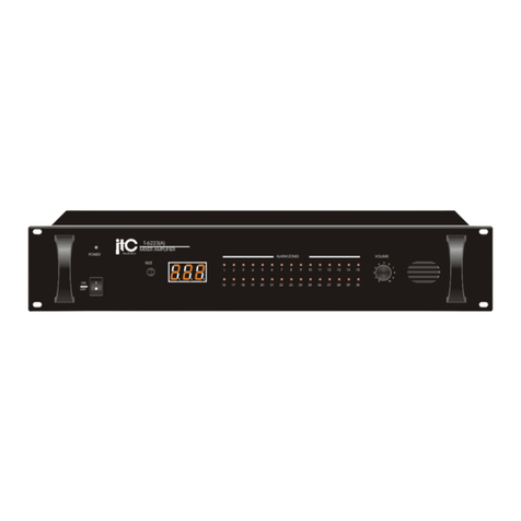
Simax QX-240 User manual

QX-240
Public Address Amplifier
USER'S MANUAL
·
Amplificador de Megafonía
MANUAL DEL USUARIO


Rev.0
ndex
1 Safety Instructions............................................................................................1
2 Functional Features..........................................................................................2
3 Front anel ......................................................................................................3
4 Rear anel .......................................................................................................4
5 Speaker wiring..................................................................................................6
5.1 Low impedance speaker connection. 4 Ω ....................................................6
5.2 High impedance speaker connection. 70/100V.............................................6
5.3 Incorrect speaker connection.........................................................................7
6 Operating Overview..........................................................................................7
7 Block Diagram...................................................................................................9
8 Frecuency Response Curve ..........................................................................10
9 Specifications..................................................................................................10


1 Safety nstructions
lease read carefully the next safety instructions.
1. Keep these instructions for future reference
2. Locate the apparatus at places nearby power socket for quick power
disconnection. Avoid places where the equipment can be an obstacle.
Disconnect the AC power supply before cleaning the equipment.
3. This appliance shall not be exposed to dripping or splashing water and that no
object filled with liquid shall be placed on the apparatus. Do not use any liquid
or spray detergent on the equipment for cleaning purposes. This appliance
should not be exposed to moisture.
4. Do not place any lit candles or similar objects on top of the apparatus.
5. Set up the equipment on a safe surface to avoid falls and damages.
6. The covering grill provides air convection. DO NOT COVER THE GRILLS. A
gap of 5 cm should be left around the perimeter of the apparatus to allow
correct ventilation.
7. The equipment shall never be opened. For safety reasons, please contact
qualified personnel.
8. The apparatus should be connected to ground for protection.
9. Ask the technician to inspect the equipment if any of the next situations occur:
a) Cable or plug is damaged.
b) Liquid has penetrated inside of the equipment.
c) The equipment has been exposed to moisture.
d) The apparatus does not work correctly or does not work according to the
user's manual.
e) The equipment has suffered a fall and has been damaged.
f) The appliance has clear signs of being damaged.
10. The wiring should be performed only by trained personnel. Disconnect all the
audio inputs and outputs while performing connections or disconnect the
equipment from the power supply. lease make sure to use the appropriate
cables.
1

User's Manual QX-240
2 Functional Features
The QX240 systems are comprehensive, all-in-one mixer-amplifier solutions for
commercial and industrial applications.These low-cost units provide all necessary features
in a simple building-block format.
1. Six microphone or line inputs with 1/4-inch phone,XLR and RCA jacks.
2. hantom power for all of MIC channels.
3. Acceptable wide range input level.
4. riority input through noise gate.
5. Three layer priority for input audio sources.
6. Seven band graphic equalizer.
7. Low distortion and low noise level.
8. Warning tone and siren transmission.
9. Integrated audio source line output.
10.Extendable by adding audio mixer and power amplifier with LINK and RE-AM
terminal.
11. Advanced protection system includes current limiting, overcurrent and thermal
protection.
12.Desktop and 19-inches rack mountable type.
13.Compact size and lightweight.
2

3 Front Panel
1. Bay for adding music source (optional)
2. Graphic equalizer control (125Hz/250Hz/500Hz/1KHz/2KHz/4KHz/8KHz)
3. rotection, output level and power indicators.
4. Input channel volume control.
5. Master volume control.
6. All speaker zone output selector.
7. Individual speaker zone output selector.
8. ower switch.
9. Evacuation siren and pre annuncement chime switch.
10. Auxiliary input (idem CH6).
11. MIC input (idem CH1).
3
Ilustration 1: QX-240 Front View

User's Manual QX-240
4 Rear Panel
1. AC fuse.
2. Speaker outputs connector ( 4-ohm, selectable 70V and 100V ).
3. AC power socket.
4. Expansion ports (Amplifier input AM -IN, Integrated mixer-equalizer output AM -
OUT, External audio processor input LINK-IN, External audio processor output LINK-
OUT ).
5. re-announce chime/siren level control.
6. Gain controls for variable input level.
7. hantom power and priority control switches.
8. Balance source input, connectors 1-3. Selectable priority inputs, 1 and 2. The
input number 1 has an equivalent jack connector MIC input on the front panel of the
4
Ilustration 2: QX-240 Rear View
Ilustration 3: Pin-out.
Unbalanced audio.

equipment. The rest of the inputs do not have priority, they are mixed.
9. riority input through noise gate. riority balanced audio input, with associated
activation threshold control (see Ilustration 5).
10. Integrated source output: origin of the input source can be chosen by the
INT/EXT selector: integrated in the front bay or the source connected to CH6. Balanced
audio output (see Ilustration 5), with associated gain control.
11. RJ45 terminal reserved for other purposes.
5
Ilustration : E/S euroblock type balanced connector
Ilustration 4: Pin-out. Signal input

User's Manual QX-240
5 Speaker wiring.
5.1 Low impedance speaker connection. 4 Ω
In order to connect conventional 4 Ω speaker systems, connect positive terminal of
the speaker (+) to 4Ω terminal. Connect the negative side (-) to COM terminal.
5.2 High impedance speaker connection. 70/100V
In order to parallel connect high impedance speaker systems (70/100V), connect the
positive side of the speaker (+) to 70/100V terminal. Connect the negative side (-) to
COM terminal.
6
Ilustration 6: Low Impedance
4 Ω speaker connection
Ilustration 7: High Impedance speaker
connection 70/100V

5.3 ncorrect speaker connection.
CAUTION: 70/100V output lines should never be used simultaneously with the low
impedance output, otherwise the equipment could be seriously damaged.
6 Operating Overview
1. ower On:
The computer is connected to the 230V AC. ress the ON/OFF switch on the front panel.
2. Manual alarm/message broadcasting:
To activate the warning tone, or alarm you must press the button on the front panel.
3. hantom ower:
This unit allows phantom power for all microphones inputs. To activate it you must activate
the corresponding switch on the rear panel.
4. Gain control input:
To adjust the gain of the inputs, the QX series features a potentiometer per input channel,
located on the rear panel. This potentiometer allows a dynamic range of 44dB.
5. riority control:
riority adjustment of the sources can be done by using the switches on the rear panel for
channels 1 and 2 "Talkover". QX240 has three priority levels :
(1) riority input (Tele- aging)
7
Ilustration 8: Incorrect speaker connection

User's Manual QX-240
(2) Notification tone and inputs 1 and 2: If several of these inputs are active, the
signal will mix them.
(3) No priority: All inputs wihtout priority will enter mixed.
8
nput Priority
1 2 (selectable)
2 2 (selectable)
3 3 No priority
4 3 No priority
5 3 No priority
6 3 No priority
Tone 2
Tele- aging 1
Table 1: Input priorities

7 Block Diagram
9
Ilustration 9: QX-240 block diagram

User's Manual QX-240
8 Frecuency Response Curve
10
Ilustration 10: Frecuency response curve

9 Specifications
Model QX-240
nput sensitivity for full output at maximum gain
Balanced Microphone Channels -50dB ± 3dB
Balanced Line Channels -22dB ± 3 dB
Balanced TELE – PAG NG input -21dB ± 3dB
Unbalanced Link-in -17dB ± 3dB
Unbalanced Amp-in 0dB ± 3dB
Frecuency Response at 1 watt from speaker out tap. 100 Hz ~
10 Khz
+0.5dB -1dB
Graphic Equalizer
125Hz,250Hz,500Hz,1kHz,2kHz,4kHz,8kHz ±12dB ± 3dB
Signal to Noise Ratio at rated power output > 90dB
Crosstalk at all control maximum -70dB at 1kHz
Output Power at THD 0.5% 240Watts
Total Harmonic Distortion(THD) at 1kHz rated power Less than 0.5%
Phantom Power 15VDC
Operating Temperature/Humidity at non-condensing 0~40° at 95% humidity
Output Voltage and mpedance
4Ω 31V
70V 20.4Ω
100V 41.6Ω
Construction
Refrigeración Convection Cooled
Dimensions (Width/Height/Depth) 420(W) x 88(H) x 320(D) mm
Net Weight 7.3 kg
11

NOTES

Table of contents
Other Simax Amplifier manuals

